Circular 16/2023/TT-BTTTT "National technical regulation on Evolved Universal Terrestial (E-UTRA FDD) Repeater – Radio Access"
- Summary
- Content
- Status
- Vietnamese
- Related documents
- Diagram
- Download
Please log in to your Advanced Package to view the full text. Do not have an account yet? Register here.
Please log in to use this function
Please log in to use this function
ATTRIBUTE
| Issuing body: | Ministry of Information and Communications | Effective date: | Known Please log in to a subscriber account to use this function. Don’t have an account? Register here |
| Official number: | 16/2023/TT-BTTTT | Signer: | Nguyen Manh Hung |
| Type: | Circular | Expiry date: | Updating |
| Issuing date: | 24/11/2023 | Effect status: | Known Please log in to a subscriber account to use this function. Don’t have an account? Register here |
| Fields: | Information - Communications |
The Effect status of this document is known.This feature is available to Advanced account holders. Please log in to a subscriber account to view Effect status. Don’t have an account? Register here
THE MINISTRY OF INFORMATION __________ | THE SOCIALIST REPUBLIC OF VIETNAM Independence - Freedom - Happiness ______________ |
No. 16/2023/TT-BTTTT | Hanoi, November 24, 2023 |
CIRCULAR
Issuing "National technical regulation on Evolved Universal Terrestial (E-UTRA FDD) Repeater – Radio Access"
Pursuant to the Law on Technical Standards and Regulations dated June 29, 2006;
Pursuant to the Law on Telecommunications dated November 23, 2009;
Pursuant to the Law on Radio Frequencies dated November 23, 2009 and the Law amending and supplementing a number of articles of the Law on Radio Frequencies dated November 9, 2022;
Pursuant to Decree No. 127/2007/ND-CP dated August 1, 2007 of the Government detailing and guiding the implementation of a number of articles of the Law on Technical Standards and Regulations;
Pursuant to Decree No. 78/2018/ND-CP dated May 16, 2018 of the Government amending and supplementing a number of articles of Decree No. 127/2007/ND-CP dated August 1, 2007 of the Government detailing the implementation of a number of articles of the Law on Technical Standards and Regulations;
Pursuant to Decree No. 48/2022/ND-CP dated July 26, 2022 of the Government stipulating the functions, tasks, powers and organizational structure of the Ministry of Information and Communications;
At the request of the Director of the Department of Science and Technology,
The Minister of Information and Communications issued a Circular stipulating the National technical regulation on Evolved Universal Terrestial (E-UTRA FDD) Repeater – Radio Access.
Article 1. Issued together with this Circular is the National Technical Regulation on Evolved Universal Terrestial (E-UTRA FDD) repeater - Radio access (QCVN 111:2023/BTTTT).
Article 2 . This Circular takes effect from July 1, 2024 and replaces Circular No. 25/2017/TT-BTTTT dated January 17, 2017 of the Minister of Information and Communications promulgating the "National technical regulation on E-UTRA FDD repeater equipment - Radio access".
Article 3. Chief of Office, Director of Department of Science and Technology, Heads of agencies and units under the Ministry of Information and Communications, Directors of Departments of Information and Communications of provinces and centrally run cities and relevant organizations and individuals are responsible for implementing this Circular./.
| MINISTER
Nguyen Manh Hung |
![]()

SOCIALIST REPUBLIC OF VIETNAM
QCVN 111:2023/BTTTT
NATIONAL TECHNICAL REGULATIONS ON EVOLVED UNIVERSAL TESSERIAL RADIO ACCESS (E-UTRA FDD) REPEATER
Hanoi - 2023
Preface
QCVN 111:2023/ BTTTT replaces QCVN 111:2017/BTTTT.
QCVN 111:2023/BTTTT compiled by the Institute of Posts and Telecommunications Science and Technology, submitted for approval by the Department of Science and Technology, appraised by the Ministry of Science and Technology, and issued by the Ministry of Information and Communications with Circular No.16/2023/TT-BTTTT dated November, 24th, 2023.

NATIONAL TECHNICAL REGULATIONS ON
EVOLVED UNIVERSAL TERRESTIAL RADIO ACCESS (E-UTRA FDD) REPEATER
1. GENERAL PROVISIONS
1.1. Scope of adjustment
This standard specifies the technical requirements for E-UTRA FDD repeater (repeater) operating in the entire frequency band or part of the frequency band specified in Table 1.
Table 1 – Frequency bands of E-UTRA FDD repeater
Frequency Band E-UTRA FDD | Transmission direction | Repeater frequency band E-UTRA FDD |
1 | Transmit | 2 110 MHz to 2 170 MHz |
Receive | 1 920 MHz to 1 980 MHz | |
3 | Transmit | 1805 MHz to 1880 MHz |
Receive | 1710 MHz to 1785 MHz | |
5 | Transmit | 869 MHz to 880 MHz |
Receive | 824 MHz to 835 MHz | |
8 | Transmit | 925 MHz to 960 MHz |
Receive | 880 MHz to 915 MHz | |
28 | Transmit | 758 MHz to 788 MHz |
Receive | 703 MHz to 7 33 MHz |
HS codes of E-UTRA FDD repeater are applied according to Appendix E.
1.2. Applicable objects
This regulation applies to Vietnamese and foreign organizations and individuals engaged in the production and trading of equipment within the scope of this regulation in the territory of Vietnam.
1.3. References
ETSI TS 136 143 (V15.0.0) (09-2018): "LTE; Evolved Universal Terrestrial Radio Access (E-UTRA); FDD repeater conformance testing (3GPP TS 36.143 version 15.0.0 Release 15)".
ETSI TS 136 141 (V15.3.0) (07-2018): "LTE; Evolved Universal Terrestrial Radio Access (E-UTRA); Base Station (BS) conformance testing (3GPP TS 36.141 version 15.3.0 Release 15)".
ETSI TS 125 141 (V15.3.0) (07-2018): "Universal Mobile Telecommunications System (UMTS); Base Station (BS) conformance testing (FDD) (3GPP TS 25.141 version 15.3.0 Release 15)".
ETSI EN 301 908-11 (V11.1.2): IMT cellular networks; Harmonized Standard covers the essential requirements of article 3.2 of the Directive 2014/53/EU; Part 11: CDMA Direct Spread (UTRA FDD) Repeaters.
ETSI TR 100 028 (all parts) V1.4.1: Electromagnetic compatibility and Radio spectrum Matters (ERM); Uncertainties in the measurement of mobile radio equipment characteristics.
Recommendation ITU-R SM.329-12 (September 2012): "Unwanted emissions in the spurious domain".
ITU-R SM.1539-1 (November 2002): “Variation of the boundary between the out-of-band and spurious domains required for the application of Recommendations ITU-R SM.1541 and ITU-R SM.329”.
TCVN 7699-2-1:2007 (IEC 60068-2-1): “Environmental testing - Part 2-1: Tests - Test A: Cold”.
TCVN 7699-2-2:2011 (IEC 60068-2-2): “Environmental testing - Part 2-2: Tests - Test B: Dry heat”.
TCVN 7699-2-6:2009 (IEC 60068-2-6): “Environmental testing - Part 2-6: Tests - Test Fc: Vibration (Sinewave)”.
TCVN 7921-3-3:2014 (IEC 60721-3-3): “Classification of environmental conditions - Part 3-3: Classification by groups of environmental parameters and severities - Stationary use in weather-protected locations”.
TCVN 7921-3-4:2014 (IEC 60721-3-4): “Classification of environmental conditions - Part 3-4: Classification by groups of environmental parameters and severities - Stationary use in unweatherproof locations”.
1.4. Word explanation
1.4.1. Carrier
The modulated waveform is transmitted over E-UTRA or UTRA (WCDMA) physical channels.
1.4.2. Channel bandwidth
The RF bandwidth supports a single E-UTRA RF carrier with a cell's uplink or downlink configured transmit bandwidth.
NOTE: The unit of measure of channel bandwidth is MHz, and is considered as a reference for transmitter and receiver RF requirements.
1.4.3. Channel edge
The lowest or highest frequency of the E-UTRA carrier.
NOTE: Channel bandwidth separates channel boundaries.
1.4.4. Donor coupling loss
Coupling loss between the repeater and the donor base station.
1.4.5. Downlink
Radio signal transmission from base station to mobile station.
1.4.6. Downlink operating band
Part of the operating frequency band is designated for downlink.
1.4.7. Nominal passband edge
The lowest and highest frequencies of the repeater bandwidth.
1.4.8. Operating band
The frequency range (paired or unpaired) is defined by a set of defined technical requirements, in which E-UTRA operates.
NOTE: The operating frequency bands of the E-UTRA repeater are declared by the manufacturer according to the regulations in Table 1. In which the operating frequency bands of the UTRA repeater are numbered in Roman numerals and the operating frequency bands of the E-UTRA repeater are numbered in Arabic numerals.
1.4.9. Output power (Pout)
The average power of a carrier at maximum gain of the repeater when the load has an impedance equal to the nominal load impedance of the transmitter.
1.4.10. Pass band
Frequency range, repeater operates according to the setup configuration.
NOTE: This frequency range may correspond to one or more consecutive nominal channels. The repeater may have one or more passbands.
1.4.11. Rated output power
The rated output power of the repeater is the average power level per carrier declared by the manufacturer to be available at the antenna connector.
1.4.12. Repeater
Device for receiving, amplifying and transmitting radiated or conducted RF carriers according to both downlink (from base station to mobile equipment areas) and uplink (from mobile equipment to base station) directions.
NOTE: Within the specified operating bands, only the uplink or downlink specified for the operating band is repeated.
1.4.13. Transmission bandwidth
Instantaneous transmission bandwidth from a user or base station, measured in resource blocks (RB).
1.4.14. Transmission bandwidth configuration
The highest transmission bandwidth licensed for the uplink or downlink within a given channel bandwidth, measured in resource blocks.
1.4.15. Uplink
Radio signal transmission from mobile station to base station.
1.4.16. Uplink operating band
Part of the operating frequency band is designated for uplink.
1.5. Symbol
∆f | The distance between the nominal passband edge frequency and the nominal -3 dB point of the measuring filter nearest to the carrier frequency. |
∆f max | The maximum value of ∆f used to determine the requirement |
BWChannel | Channel bandwidth |
BWConfig | Transmit bandwidth configuration, unit is MHz, where BWconfig = NRB × 180 kHz in uplink and BWconfig = 15 kHz + N RB × 180 kHz in downlink |
BWMeas | Measurement bandwidth |
BW Pass band | Bandwidth of the repeater bandwidth |
f_offset max | The maximum value of f_offset used to determine the request |
FDL_low | Lowest frequency of downlink operating band |
FDL_high | Highest frequency of downlink operating band |
Ffilter | Filter center frequency |
FUL_low | Lowest frequency of the uplink operating band |
FUL_high | Highest frequency of uplink operating band |
NDL | EARFCN downlink |
NOffs-DL | Offset for calculating downlink EARFCN |
NOffs-UL | Offset for calculating uplink EARFCN |
NRB | Transmission bandwidth configuration, expressed in resource block units |
NUL | EARFCN uplink |
PEM,N | Emission level declared for N channel |
PEM,B32,ind | Declared emission level in Band 32, ind = a,b,c,d,e |
Pmax | Maximum output power |
Pout | Output power |
1.6. Abbreviations
ACLR | Adjacent Channel Leakage Ratio |
|
ACRR | Adjacent Channel Rejection Ratio |
|
BS | Base Station |
|
BW | Bandwidth |
|
CA | Carrier Aggregation |
|
CW | Continuous Wave |
|
DTT | Digital Terrestrial Television |
|
DUT/EUT | Device Under Test/Equipment Under Test |
|
EARFCN | E-UTRA Absolute Radio Frequency Channel Number |
|
EFTA | European Free Trade Association |
|
ERM | Electromagnetic compatibility and Radio spectrum Matters |
|
E-TM | E-UTRA Test Model |
|
E-UTRA | Evolved Universal Terrestrial Radio Access |
|
FDD | Frequency Division Duplex |
|
GSM | Global System for Mobile communications |
|
IMT | International Mobile Telecommunications |
|
ITU-R | International Telecommunication Union - Radiocommunication |
|
LTE | Long Term Evolution, also known as E-UTRA |
|
MS | Mobile Station |
|
MSG | Mobile Standards Group |
|
PCCPCH | Primary Common Control Physical Channel |
|
RF | Radio Frequency |
|
RMS | Root Mean Square (value) |
|
RRC | Root Raised Cosine |
|
RSS | Root Sum Square |
|
SCCPCH | Secondary Common Control Physical Channel |
|
TDD | Time Division Duplex |
|
TFES | Task Force for European Standards for IMT |
|
UARFCN | UTRA Absolute Radio Frequency Channel Number |
|
UMB | Ultra Mobile Broadband |
|
UTRA | Universal Terrestrial Radio Access |
|
WCDMA | Wideband Code Division Multiple Access |
|
2. TECHNICAL REGULATIONS
2.1. Environmental conditions
The technical requirements of this standard apply under the operating environmental conditions of the equipment as declared by the supplier. The equipment shall fully comply with all the technical requirements of this standard when operating in the boundary limits of the declared operating environmental conditions.
Appendix B provides guidance to suppliers on how to declare environmental conditions.
2.2. Technical requirements
2.2.1. Technical requirements and corresponding measurement methods
This standard specifies technical requirements and corresponding measurement methods for equipment within the scope of this standard.
Table 2 – Technical requirements for E-UTRA repeaters
Technical requirements | Corresponding measurement method |
2.2.2. Unwanted emissions operating band | 3.3.1 |
2.2.3. Spurious emissions | 3.3.2 |
2.2.4. Maximum output power | 3.3.3 |
2.2.5. Input intermodulation | 3.3.4 |
2.2.6. Out-of-band gain | 3.3.5 |
2.2.7. Adjacent channel compression factor | 3.3.6 |
2.2.8. Output intermodulation | 3.3.7 |
2.2.9. Radiation emission | 3.3.8 |
NOTE: The operating frequency band for the repeater is declared by the manufacturer. For repeaters operating in multiple frequency bands, the test for each technical requirement is performed according to the provisions of 3.
2.2.2. Unwanted emissions operating band
2.2.2.1. Definition
Unwanted emissions include out-of-band emissions and spurious emissions. Out-of-band emissions are emissions outside the channel bandwidth, caused by the modulation process and nonlinearities in the transmitter, excluding spurious emissions. Spurious emissions are emissions caused by unwanted transmitter effects such as harmonics, parasitic emissions, intermodulation products and frequency conversion products, but excluding out-of-band emissions.
The repeater out-of-band emissions requirement specifies both out-of-band unwanted emissions and protection for base station receivers in the uplink operating band. The operating band unwanted emissions define all unwanted emissions in the repeater operating band plus a 10 MHz band below and above. Unwanted emissions outside this band are limited to spurious emissions requirements.
2.2.2.2. Limit
2.2.2.2.1. Overview
Emissions not exceeding the limit specified in the tables below, in which:
- ∆f is the distance from the nominal passband edge frequency and the nominal -3 dB point of the nearest measuring filter to the carrier frequency.
- The nominal bandwidth margins are the lowest and highest frequencies of the repeater bandwidth.
- BWMeas is the measurement bandwidth.
- BWPass band is the bandwidth of the repeater device.
- f_offset is the offset from the nominal passband edge frequency to the center of the measurement filter.
- f_offset max is the frequency offset f_offset of frequencies outside the operating band of the repeater by 10 MHz.
- ∆f max is equal to f_offset max minus half the bandwidth of the measurement filter.
All claims are measured in average power (RMS).
The requirements apply to the uplink and downlink, with the maximum gain and input signal as follows:
- No E-UTRA input signal;
- E-UTRA input signal within the repeater's passband at a level that produces the maximum rated output power for each channel;
- Increases the E-UTRA input signal in all channels in the passband by 10 dB above the input signal level to produce the maximum rated output power.
2.2.2.2.2. Unwanted emissions operating band
For E-UTRA FDD repeaters operating in bands 1, 3, 5 and 8 emissions shall not exceed the limits specified in Table 3 to Table 5. The test is applied to both the uplink and downlink of the repeater.
Table 3 – General limits of unwanted emissions band operation for repeater bandwidth ![]() 5 MHz for E-UTRA bands 1, 3, 5 and 8
5 MHz for E-UTRA bands 1, 3, 5 and 8
Frequency deviation at the -3 dB point of the measuring filter, ∆f | Frequency offset at the center frequency of the measuring filter, f_offset | Limit | Measurement bandwidth |
0 MHz ≤ ∆f < 0.2 MHz | 0.015 MHz ≤ f_offset < 0.215 MHz | -12.5 dBm | 30kHz |
0.2 MHz ≤ ∆f < 1 MHz | 0.215 MHz ≤ f_offset < 1.015 MHz | -12.5dBm – 15× | 30kHz |
| 1.015 MHz ≤ f_offset < 1.5 MHz | -24.5 dBm | 30kHz |
1 MHz ≤ ∆f < 2 x BW Pass band | 1.5 MHz ≤ f_offset < 2 x BW Pass band + 0.5 MHz | -11.5 dBm | 1 MHz |
2 x BW Pass bands MHz ≤ ∆f < ∆f max | 2 x BW Pass bands + 0 .5 MHz ≤ f_offset < f_offset max | -15 dBm | 1 MHz |
NOTE 1: The unit of measurement for frequency and bandwidth is MHz. NOTE 2: The requirements for 1.4 MHz and 3 MHz bandwidths are applied only to band 8. | |||
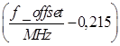
Table 4 – General limits of unwanted emissions band operation for repeater bandwidth ![]() 5 MHz for E-UTRA bands 1, 3, 5 and 8
5 MHz for E-UTRA bands 1, 3, 5 and 8
Frequency deviation at the -3 dB point of the measuring filter, ∆f | Frequency offset at the center frequency of the measuring filter, f_offset | Limit | Measurement bandwidth |
0 MHz ≤ ∆f < 0.2 MHz | 0.015 MHz ≤ f_offset < 0.215 MHz | -12.5 dBm | 30kHz |
0.2 MHz ≤ ∆f < 1 MHz | 0.215 MHz ≤ f_offset < 1.015 MHz | -12.5dBm – 15× | 30kHz |
| 1.015 MHz ≤ f_offset < 1.5 MHz | -24.5 dBm | 30kHz |
1 MHz ≤ ∆f < 10 MHz | 1.5 MHz ≤ f_offset < 10.5 MHz | -11.5 dBm | 1 MHz |
10 MHz ≤ ∆f < ∆f max | 10.5 MHz ≤ f_offset < f_offset max | -15 dBm | 1 MHz |
NOTE: The unit of measurement for frequency and bandwidth is MHz. | |||
Table 5 – Conditional limits of unwanted emissions operating band for E-UTRA bands 1, 3, 5 and 8
Frequency deviation at the -3 dB point of the measuring filter, ∆f | Frequency offset at the center frequency of the measuring filter, f_offset | Limit | Measurement bandwidth |
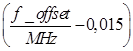
0 MHz ≤ ∆f < 0.05 MHz | 0.015 MHz ≤ f_offset < 0.065 MHz | 6.5dBm – 60 × | 30kHz |
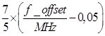
0.05 MHz ≤ ∆f < 0.15 MHz | 0.065 MHz ≤ f_offset < 0.165 MHz | 3.5dBm – 160 ×
| 30kHz |
0.15 MHz ≤ ∆f < 0.2 MHz | 0.165 MHz ≤ f_offset < 0.215 MHz | -12.5 dBm | 30kHz |
NOTE 1: The unit of measurement for frequency and bandwidth is MHz. NOTE 2: The requirements for 1.4 MHz and 3 MHz bandwidths are applied only to band 8. | |||
For E-UTRA FDD repeaters operating in band 28, emissions shall not exceed the limits specified in Table 6. The test shall be applied to both the uplink and downlink of the repeater.
Table 6 – General limits of unwanted emissions operating band for repeater bandwidth ![]() 5 MHz for E-UTRA band 28
5 MHz for E-UTRA band 28
Frequency deviation at the -3 dB point of the measuring filter, ∆f | Frequency offset at the center frequency of the measuring filter, f_offset | Limit | Measurement bandwidth |
0 MHz ≤ ∆f < 5 MHz | 0.05 MHz ≤ f_offset < 5.05 MHz | -5.5 dBm – | 100kHz |
5 MHz ≤ ∆f < 10 MHz | 5.05 MHz ≤ f_offset < 10.05 MHz | -12.5 dBm | 100kHz |
10 MHz ≤ ∆f < ∆f max | 10.05 MHz ≤ f_offset < f_offset max | -1 6 dBm | 100kHz |
NOTE: The unit of measurement for frequency and bandwidth is MHz. | |||
2.2.2.2.3. Protection for base station receivers in the operating band
The requirement applies to the protection of E-UTRA FDD base station receivers deployed in the same geographical area as E-UTRA FDD repeaters.
The requirement applies at frequencies within 10 MHz of the repeater bandwidth.
The requirement is applied to the uplink of the repeater, with maximum gain.
The power of any unwanted emission in the operating frequency band shall not exceed the limits specified in Table 7.
Table 7 - Repeater uplink operating band unwanted emissions limits for base station receiver protection
Limit | Measurement bandwidth | Attention |
-53 dBm | 100kHz |
|
NOTE 1: The requirements in Table 7 for the repeater uplink direction reflect what is achievable with the current state of the art and are based on a 73 dB coupling loss between the repeater and the E-UTRA FDD base station receiver. NOTE 2: Requirements will be reviewed as the state of the art develops. | ||
2.2.2.2.4. Joint operation in neighbouring bands
The requirement applies to protection in bands neighbouring to band 1.
This requirement applies only to the uplink of the repeater.
The power of any unwanted emission in the operating band shall not exceed the limits specified in Table 8.
Table 8 – Limits unwanted emissions in the repeater uplink operating band to protect neighbouring band operations
Operating frequency | Frequency Band | Limit | Measurement bandwidth |
1 | 2 110 MHz to 2 1 05 MHz | -30 + 3.4 (f - 2 110 MHz) dBm | 1 MHz |
2 1 05 MHz to 2 170 MHz | -30 + 3.4 (2 170 - f MHz) dBm | 1 MHz |
2.2.2.3. Measurement method
Use the test measurements as specified in 3.3.1.
2.2.3. Spurious emission
2.2.3.1. Definition
Spurious emissions are emissions caused by unwanted transmitter effects such as harmonics, parasitic emissions, intermodulation products and frequency conversion products, but do not include out-of-band emissions. Spurious emissions are measured at the output port of the repeater.
The spurious emission limits apply to the frequency range 9 kHz to 12.75 GHz, excluding the frequency range from 10 MHz below the lowest frequency of the repeater operating band to 10 MHz above the highest frequency of the repeater operating band.
The requirements of 2.2.3.2 shall be applied to all types of repeaters considered (single or multiple operating bands). This requirement is applied to all configurations foreseen in accordance with the manufacturer's published specifications. The test shall be performed on both the uplink and downlink of the repeater.
All requirements are measured as effective power (RMS), unless otherwise specified.
2.2.3.2. Limit
2.2.3.2.1. Overview
The requirements apply to the uplink and downlink of the repeater, with maximum gain and input signals as follows:
- No E-UTRA input signal;
- E-UTRA input signal within the repeater's passband at a level that produces the maximum rated output power for each channel;
- Increases the E-UTRA input signal in all channels in the passband by 10 dB above the input signal level to produce the maximum rated output power.
2.2.3.2.2. Spurious emissions
Spurious emission power does not exceed the limit specified in Table 9.
Table 9 – General limits for spurious emissions
Frequency range | Limit | Measurement bandwidth | Attention |
9kHz ↔ 150kHz | -36 dBm | 1kHz | The bandwidth specified in 4.1 of Recommendation ITU-R SM.329-12. |
150kHz ↔ 30MHz | -36 dBm | 10kHz | The bandwidth specified in 4.1 of Recommendation ITU-R SM.329-12. |
30MHz ↔ 1GHz | -36 dBm | 100kHz | The bandwidth specified in 4.1 of Recommendation ITU-R SM.329-12. |
1 GHz ↔ 12.75 GHz | -30 dBm | 1 MHz | The bandwidth specified in 4.1 of Recommendation ITU-R SM.329-12. Higher frequencies specified in Table 1 at 2.5 of Recommendation ITU-R SM.329-12. |
2.2.3.2.3. Interoperate with other systems in the same geographic area
This requirement is applied to the protection of UE /MS and BS/BTS receivers of other systems.
The power of spurious emissions of the E-UTRA repeater shall not exceed the limits set out in specified in Table 10 when operating in conjunction with other systems in the first column.
Table 10 – Spurious emission limits for E-UTRA FDD repeaters in the geographic coverage area of systems operating in other frequency bands
System protected | Operation request | Limit | Measurement bandwidth | Attention |
GSM 900 | 921 MHz to 960 MHz | -57 dBm | 100kHz | This requirement does not apply to E-UTRA FDD repeaters operating in band 8. |
876 MHz to 915 MHz | -61 dBm | 100kHz | This requirement does not apply to the uplink of E-UTRA FDD repeaters operating in band 8. | |
DCS 1800 | 1805 MHz to 1880 MHz | -47 dBm | 100kHz | This requirement does not apply to E-UTRA FDD repeaters operating in band 3. |
1710 MHz to 1785 MHz | -61 dBm | 100kHz | This requirement does not apply to the uplink of E-UTRA FDD repeaters operating in band 3. | |
WCDMA FDD band 1, E-UTRA band 1 | 2110 MHz to 2170 MHz | -52 dBm | 1 MHz | This requirement does not apply to E-UTRA FDD repeaters operating in band 1. |
1920 MHz to 1980 MHz | -49 dBm | 1 MHz | This requirement does not apply to the uplink of E-UTRA FDD repeaters operating in band 1. | |
E-UTRA band 3 | 1805 MHz to 1880 MHz | -52 dBm | 1 MHz | This requirement does not apply to E-UTRA FDD repeaters operating in band 3. |
1710 MHz to 1785 MHz | -49 dBm | 1 MHz | This requirement does not apply to the uplink of E-UTRA FDD repeaters operating in band 3. | |
E-UTRA band 5 | 869 MHz to 894 MHz | -52 dBm | 1 MHz | This requirement does not apply to E-UTRA FDD repeaters operating in band 5. |
824 MHz to 849 MHz | -49 dBm | 1 MHz | This requirement does not apply to the uplink of E-UTRA FDD repeaters operating in band 5. | |
WCDMA FDD band VIII, E-UTRA band 8 | 925 MHz to 960 MHz | -52 dBm | 1 MHz | This requirement does not apply to E-UTRA FDD repeaters operating in band 8. |
880 MHz to 915 MHz | -49 dBm | 1 MHz | This requirement does not apply to the uplink of E-UTRA FDD repeaters operating in band 8. | |
E-UTRA band 28 | 758 MHz to 788 MHz | -52 dBm | 1 MHz | This requirement does not apply to E-UTRA FDD repeaters operating in band 28. |
703 MHz to 733 MHz | -49 dBm | 1 MHz | This requirement does not apply to the uplink of E-UTRA FDD repeaters operating in band 28. | |
NOTE: The -53 dBm/100 kHz requirement in this table for the repeater uplink reflects what is achievable with the current state of the art based on the coupling loss between the repeater and the UTRA TDD base station receiver. | ||||
2.2.3.3. Measurement method
Use the test measurements as specified in 3.3.2.
2.2.4. Maximum output power
2.2.4.1. Definition
The output power, Pout, of a repeater is the average power level of a carrier at maximum gain of the repeater when loaded with an impedance equal to the nominal load impedance of the transmitter.
The maximum output power, Pmax, of the repeater is the average power level per carrier measured at the antenna connector under specified reference conditions.
The requirement applies to the uplink and downlink of the repeater, at maximum gain.
2.2.4.2. Limit
The requirements apply at maximum gain, with E-UTRA signals in the repeater bandwidth at a level that produces the maximum rated output power for each channel.
When the power of all signals is increased by 10 dB, compare with the signal power level that produces the maximum rated output power.
Under normal conditions, the maximum output power of the repeater is within the limits specified in Table 11 for the nominal output power as declared by the manufacturer.
Table 11 – Repeater output power under normal conditions
Rated output power | Carrier frequency | Limit |
P ≥ 31 dBm | f ≤ 3.0 GHz | ± 2.7 dB |
P < 31 dBm | f ≤ 3.0 GHz | ± 3.7 dB |
Under extreme conditions, the maximum output power of the repeater is within the limits specified in Table 12 for the manufacturer's declared nominal output power.
Table 12 – Repeater output power under extreme conditions
Rated output power | Carrier frequency | Limit |
P ≥ 31 dBm | f ≤ 3.0 GHz | ± 3.2 dB |
P < 31 dBm | f ≤ 3.0 GHz | ± 4.7 dB |
2.2.4.3. Measurement method
Use the test measurements as specified in 3.3.3.
2.2.5. Input intermodulation
2.2.5.1. Definition
Input intermodulation is a measure of the repeater's ability to prevent interference from occurring within the operating frequency band, in the presence of interfering signals on frequencies other than the operating band.
Mixing the third and higher harmonics of two interfering RF signals can produce an interfering signal in the frequency band of the desired channel. Intermodulation response rejection is a measure of the repeater's ability to maintain the desired frequency free from internal interference.
This requirement applies to the uplink and downlink of the repeater, at maximum gain.
2.2.5.2. Limit
2.2.5.2.1. General requirements for input intermodulation
Intermodulation requirements shall be met when the following signals are applied to the repeater.
- f1 offset is the offset from the channel edge frequency of the first or last channel in the passband of the closer carrier.
Table 13 – General requirements for input intermodulation
f1 offset | Signal to noise level | Signal type | Measurement bandwidth |
1.0 MHz | -40 dBm | 2 CW carriers | 1 MHz |
For the parameters specified As specified in Table 13, the power in the operating band shall not exceed the limits in Table 14 at the output of the repeaters when measured at the centre of the passband, relative to the level obtained in the absence of interfering signals.
Table 14 – General limits with input intermodulation
Limits on power increase in operating band |
+ 11.2 dB |
2.2.5.2.2. Works with other systems
The intermodulation requirement shall be met when the following signals are applied to the repeater.
Table 15 – Input intermodulation requirements for interfering signals in coexisting systems
Coexistence with other systems | Frequency of the interference signals | Signal to noise level | Signal type | Measurement bandwidth | Attention |
GSM 900 | 876 MHz to 915 MHz | -15 dBm | 2 CW carriers | 1 MHz | The requirement is not applied to E-UTRA FDD repeaters operating in band 8 as they are included in the requirements at 2.2.5.2.1 |
DCS1800 | 1710 MHz to 1785 MHz | -15 dBm | 2 CW carriers | 1 MHz | The requirement is not applied to E-UTRA FDD repeaters operating in band 3 as they are included in the requirements at 2.2.5.2.1 |
WCDMA FDD band 1, E-UTRA band 1 | 1920 MHz to 1980 MHz | -15 dBm | 2 CW carriers | 1 MHz | The requirement is not applied to E-UTRA FDD repeaters operating in band 1 as they are included in the requirements at 2.2.5.2.1 |
E-UTRA band 3 | 1710 MHz to 1785 MHz | -15 dBm | 2 CW carriers | 1 MHz | The requirement is not applied to E-UTRA FDD repeaters operating in band 3 as they are included in the requirements at 2.2.5.2.1 |
E-UTRA band 5 | 824 MHz to 849 MHz | -15 dBm | 2 CW carriers | 1 MHz | The requirement is not applied to E-UTRA FDD repeaters operating in band 5 as they are included in the requirements at 2.2.5.2.1 |
WCDMA FDD band VIII, E-UTRA band 8 | 880 MHz to 915 MHz | -15 dBm | 2 CW carriers | 1 MHz | The requirement is not applied to E-UTRA FDD repeaters operating in band 8 as they are included in the requirements at 2.2.5.2.1 |
E-UTRA band 28 | 703 MHz to 733 MHz | -15 dBm | 2 CW carriers | 1 MHz | The requirement is not applied to E-UTRA FDD repeaters operating in band 28 as they are included in the requirements at 2.2.5.2.1 |
NOTE: The coexistence requirements in this table are not applied when the repeater bandwidth frequency range is neighbouring to the frequency range of the coexistence requirements in this table. Current state of the art technology does not allow a universal solution to the problem of coexistence with other systems. | |||||
For the parameters specified in Table 15, the power in the operating frequency band shall not exceed the limits specified in Table 16 at the output of the repeater when measured at the centre of the operating frequency band, compared with the level obtained in the absence of interfering signals.
Table 16 – General limits with input intermodulation
Limits on power increase in operating band |
+ 11.2 dB |
2.2.5.3. Measurement method
Use the test measurements as specified in 3.3.4.
2.2.6. Out-of-band gain
2.2.6.1. Definition
Out-of-band gain refers to the gain of the repeater just outside the operating frequency band. Measurements shall be applied to the uplink and downlink of the repeater, with the gain values at maximum.
2.2.6.2. Limit
The use of repeaters in a system is intended to amplify in-band signals and not amplify out-of-band emissions of the donor base station.
For that purpose, in repeater applications, the out-of-band gain is less than the donor coupling loss. This loss is the minimum loss between the BS donor and the repeater for proper operation of the repeater, since manufacturer announced
Gain outside the operating band does not exceed the limit specified in Table 17, in which:
- f_offset_CW The offset between the outer channel edge frequency of the outer channel in the passband and a CW signal.
Table 17 – Limit 1 of out-of-band gain
Frequency offset, f_offset_CW | Maximum gain |
0.2 ≤ f_offset_CW < 1.0 MHz | 60.5 dB |
1.0 ≤ f_offset_CW < 5.0 MHz | 45.5 dB |
5.0 ≤ f_offset_CW < 10.0 MHz | 45.5 dB |
10.0 MHz ≤ f_offset_CW | 35.5 dB |
For 10.0 MHz ≤ f_offset, the out-of-band gain does not exceed the limits specified in Table 18. .
Table 18 – Limit 2 of out-of-band gain
Frequency offset, f_offset_CW | Carrier frequency | Maximum gain |
10.0 MHz ≤ f_offset_CW | f ≤ 3.0 GHz | Out-of-band gain ≤ Minimum loss donor coupling loss + 0.5 dB |
2.2.6.3. Measurement method
Use the test measurements as specified in 3.3.5.
2.2.7. Adjacent channel compression factor
2.2.7.1. Definition
Adjacent Channel Repression Ratio (ACRR) is the ratio of the RRC loaded gain for each in-band repeater carrier to the RRC loaded gain of the repeater on the out-of-band neighbouring channel. The in-band and adjacent channel carriers of same type (reference carrier).
This request shall apply to the uplink and downlink of the repeater, at maximum gain, where the donor link is maintained across the (repeater) antennas.
2.2.7.2. Limit
2.2.7.2.1. ACRR
There are no minimum requirements for E-UTRA signals.
2.2.7.2.2. Joint activities with UTRA
The requirement applies to the protection of UTRA signals in a geographical area where E-UTRA FDD repeaters and UTRA base stations are deployed. The reference carrier is the UTRA FDD carrier.
Under normal conditions, ACRR does not exceed the given limit. specified in Table 19.
Table 19 – ACRR of repeater
Coexistence with other systems | Repeater maximum output power | Channel offset from the center frequency of the first or last 5 MHz channel in the passband | ACRR Limit |
UTRA | P ≥ 31 dBm | 5 MHz | 32.3 dB |
P ≥ 31 dBm | 10 MHz | 32.3 dB | |
P < 31 dBm | 5 MHz | 19.3 dB | |
P < 31 dBm | 10 MHz | 19.3 dB | |
NOTE: The maximum output power of the repeater is defined in ETSI EN 301 908-11. | |||
2.2.7.3. Measurement method
Use the test measurements as specified in 3.3.6.
2.2.8. Output intermodulation
2.2.8.1. Definition
The output intermodulation requirement is a measure of the repeater's ability to prevent the generation of signals created by intermodulation products due to the interfering signal reaching the repeater through the output port.
The output intermodulation level is the power of the intermodulation products when the 5 MHz E-UTRA interfering signal is applied to the output port at a level 30 dB lower than the desired signal level. The desired signal channel bandwidth BWChannel shall be the maximum bandwidth supported by the repeater. The deviation of the interfering signal center frequency from the desired carrier center frequency shall comply with the provisions of Table 20.
The requirement is applicable to downlink signals, at maximum gain.
Table 20 – Interfering and desired signals for output intermodulation requirements
Parameters | Value |
Desired signal | E-UTRA signal of maximum channel bandwidth BWChannel |
Type of interference signal | E-UTRA signal of 5 MHz channel bandwidth |
Signal to noise level | The average power level is 30 dB lower than the desired signal average power |
Deviation of the interfering signal center frequency from the desired carrier signal center frequency | BWChannel /2 – 12.5 MHz BWChannel /2 – 7.5 MHz BWChannel /2 – 2.5 MHz BWChannel /2 + 2.5 MHz BWChannel /2 + 7.5 MHz BWChannel /2 + 12.5 MHz |
Interfering signal locations located partially or entirely outside the downlink operating band of the repeater are excluded from the requirements in the above table.
2.2.8.2. Limit
The output intermodulation level shall not exceed the operating band unwanted emissions requirements of 2.2.2.2 or the downlink spurious emissions requirements of 2.2.3.2.1
2.2.8.3. Measurement method
Use the test measurements as specified in 3.3.7.
2.2.9. Radiation emission
2.2.9.1. Definition
This criterion evaluates the ability to limit unwanted emissions from the enclosure port of the E-UTRA FDD repeater.
This specification applies to E-UTRA FDD repeater equipment.
Measurement of this specification shall be performed on a representative configuration of the equipment under test.
2.2.9.2. Limit
The frequency margins and reference bandwidths for the detailed transitions of the limits between the requirements for out-of-band emissions and the requirements for spurious emissions are based on ITU-R Recommendations SM.329-12 and SM.1539-1.
The requirements in Table 21 apply only to frequencies in the emission domain.
Table 21 – Requirements for radiated spurious emissions
Frequency | Minimum Requirements (ERP)/ Reference Bandwidth | Availability |
30 MHz ≤ f < 1 000 MHz | -36 dBm/100 kHz | All |
1 GHz ≤ f < 12.75 GHz | -30 dBm/1 MHz | All |
2.2.9.3. Measurement method
Use the test measurements as specified in 3.3.8.
3. MEASUREMENT METHOD
3.1. Test conditions
The measurements specified in this standard shall be carried out at representative points within the boundary limits of the declared operating environmental conditions.
At points where technical specifications change depending on environmental conditions, Tests shall be carried out under a full range of environmental conditions (within the boundary limits of the declared operating environmental conditions) to verify compliance with the affected technical requirements.
Normally all measurements need only be performed under normal test conditions unless otherwise specified.
The measurement system diagram specified for each test is described in Annex C.
3.2. Interpretation of measurement results
The results recorded in the test report for the measurements described in this standard shall be interpreted as follows:
- The measured value associated with the corresponding limit shall be used to decide whether the equipment meets the requirements of the standard;
- The measurement uncertainty value for each parameter measurement shall be included in the test report;
- For each measurement, the recorded value of the measurement uncertainty shall be equal to or less than the values specified in Tables 22.
According to this standard, for measurement methods, the values of measurement uncertainty must be calculated according to TR 100 028 and must correspond to an expansion factor (coverage factor) k = 1.96 (this factor specifies a confidence level of 95% in the case where the distributions characterizing the actual measurement uncertainty are Gaussian).
Table 22 – Maximum measurement uncertainty of system measurement
Parameters | Conditions | Measurement uncertainty |
Unwanted emissions in the operating band (except protection for base station receivers in the operating band) | f ≤ 3.0 GHz The ACLR noise of the signal generator must be at least 10 dB vs. base station ACLR noise according to ETSI TS 136 141 | ±1.5 dB
|
Protection for base station receivers in operating frequency bands | With results > -60 dBm With results < -60 dBm | ±2.0 dB ±3.0 dB |
Spurious emission | In E-UTRA and coexisting receiver bands: With results > -60 dBm With results < -60 dBm Outside the range: Emission power 9 kHz < f ≤ 4 GHz The ACLR interference of the transmitter must be at least 10dB lower than the ACLR interference of the base station according to ETSI TS 136 141 |
±2.0 dB ±3.0 dB
±2.0 dB
|
Output power | f ≤ 3.0 GHz | ±0.7 dB |
Input intermodulation characteristics | Recipe:
| ±1.2 dB |
Out-of-band gain | f ≤ 3.0 GHz Calibration in the test arrangement must be performed without the equipment under test to achieve accuracy. | ±0.5 dB
|
Intermodulation output | Unwanted emissions operating band: The ACLR interference of the transmitter must be at least 10dB lower than the ACLR interference of the base station according to ETSI TS 136 141 Spurious Emission: In UTRA and coexisting receiver bands: With results > -60 dBm With results < -60 dBm Outside the range: Emission power 9 kHz < f ≤ 4 GHz The interference signal shall have a spurious emission level at least 10 dB lower than the spurious level required in section 2.2.3.2. | ±2.1 dB
±2.0 dB ±3.0 dB
±2.0 dB
|
Adjacent channel compression factor |
| ± 0.7 dB |
NOTE 1: For RF tests, it should be noted that the uncertainties in this table apply to the Test System operating with a nominal 50 Ω load and do not include system effects due to mismatch between the EUT and the Test System. | ||
NOTE 2: If the Test System for the test has a measurement uncertainty greater than that specified in this table , the equipment may still be used, provided that the following adjustments are made: Any additional uncertainty introduced into the Test System beyond that specified in this table should be used to tighten the Limits - making the test more difficult to pass (for some tests, e.g. receiver tests, this may require changing the reference input signals). | ||
3.3. Measurement of essential parameters for the radio section
3.3.1. Unwanted emissions operating band
3.3.1.1. Initial conditions
Test environment: normal, see B.1 of Annex B.
Arrange equipment according to Appendix C.
1) Connect the signal generator to the input port of the repeater.
2) Detection mode: True RMS.
3.3.1.2. Measurement procedure
1) Set the repeater to maximum gain.
2) Set up the signal generator(s) to generate the signal(s) according to Table 23.
Table 23 – Reference input signals for operating band unwanted emissions testing
Transmission direction and bandwidth | Reference input signal | Note |
Downlink, BWPass band < 2.8 MHz | Repeater device reference input signal 4 | The signal is defined at C.4 of Appendix C |
Uplink, BWPass band < 2.8 MHz | Repeater 3 reference input signal | The signal is defined at C.3 of Appendix C |
Downlink, BWPass band ≥ 2.8 MHz | Repeater 2 reference input signal | The signal is defined at C.2 of Appendix C |
Uplink, BWPass band ≥ 2.8 MHz | Repeater device reference input signal 1 | The signal is defined at C.1 of Appendix C |
3) The measuring device must be configured with the measurement bandwidth as shown in the test requirements table.
4) Measure the emission at the specified frequencies with the specified measurement bandwidth and take care that the measured value does not exceed the specified value. For the selection of the table and limits, use the repeater bandwidth and the reference input signal if necessary.
5) Increase the input power by 10 dB above the level achieved in step 2.
6) Measure the emission at the specified frequencies with the specified measurement bandwidth and take care that the measured value does not exceed the specified value. For the selection of the table and limits, use the repeater bandwidth and the reference input signal if necessary.
7) If the repeater bandwidth is wider than 2.8 MHz, repeat steps 1 through 6 with a new reference input signal of the same type but using different center frequencies so that all signals fit within the repeater bandwidth.
8) Turn off the input signal to the repeater.
9) Measure the emission at the specified frequencies with the specified measurement bandwidth and take care that the measured value does not exceed the specified value. For table selection and limit, use the repeater bandwidth.
NOTE: As a general rule, the resolution bandwidth of the measuring device should be equal to the measurement bandwidth. However, to increase the measurement accuracy, sensitivity and efficiency, the resolution bandwidth can be smaller than the measurement bandwidth. In this case, the result will have to be integrated over the measurement bandwidth to obtain the equivalent noise bandwidth of the measurement bandwidth.
3.3.2. Spurious emission
3.3.2.1. Initial conditions
Test environment: normal, see B.1 of Appendix B.
Arrange equipment according to Appendix C.
1) Connect the signal generator to the input port of the repeater.
2) Detection mode: True RMS
3.3.2.2. Measurement procedure
1) Set the repeater to maximum gain.
2) Set up the signal generator(s) to generate the signal(s) according to Table 24.
Table 24 – Reference input signals for operating band unwanted emissions testing
Transmission direction and bandwidth | Reference input signal | Note |
Downlink, BW Pass band < 2.8 MHz | Repeater device reference input signal 4 | The signal is defined at C.4 of Appendix C |
Uplink, BW Pass band < 2.8 MHz | Repeater 3 reference input signal | The signal is defined at C.3 of Appendix C |
Downlink, BW Pass band ≥ 2.8 MHz | Repeater 2 reference input signal | The signal is defined at C.2 of Appendix C |
Uplink, BW Pass band ≥ 2.8 MHz | Repeater device reference input signal 1 | The signal is defined at C.1 of Appendix C |
At center frequencies such that the entire signal is within the passband and at the level(s) producing the manufacturer's published maximum output power with maximum gain.
3) The measuring device must be configured with the measurement bandwidth as shown in the test requirements table.
4) Measure the emission at the specified frequencies with the specified measurement bandwidth and take care that the measured value does not exceed the specified value. For the selection of the table and limits, use the repeater bandwidth and the reference input signal if necessary.
5) Increase the input power by 10 dB above the level achieved in step 2.
6) Measure the emission at the specified frequencies with the specified measurement bandwidth and take care that the measured value does not exceed the specified value. For the selection of the table and limits, use the repeater bandwidth and the reference input signal if necessary.
7) If the repeater bandwidth is wider than 2.8 MHz, repeat steps 1 through 6 with a new reference input signal of the same type but using different center frequencies so that all signals fit within the repeater bandwidth.
8) Turn off the input signal to the repeater.
9) Measure the emission at the specified frequencies with the specified measurement bandwidth and take care that the measured value does not exceed the specified regulated value.
3.3.3. Maximum output power
3.3.3.1. Initial conditions
Test environment: normal, see B.1 of Appendix B.
Arrange equipment according to Appendix C.
Additionally, on a single UARFCN, the test shall be performed under extreme power conditions as specified in A.1.
NOTE: Test measurements are performed with extreme power sources and extreme temperatures.
1) Connect the signal generator device to the repeater input port.
2) Connect the power meter to the repeater output port.
3.3.3.2. Measurement procedure
1) Set the signal generator to have the transmit signal as shown in Table 25.
Table 25 – Reference input signals for output power testing
Repeater orientation under test and bandwidth | Reference input signal | Note |
Way down | An E-TM1.1 of the widest bandwidth suitable for the repeater bandwidth | The signal is defined at ETSI TS 136 141 |
Uplink BW Pass band < 2.8 MHz | Input signal reference repeater 3 | The signal is defined at C.3 of Appendix C |
Uplink BW Pass band ≥ 2.8 MHz | Input signal reference repeater 1 | The signal is defined at C.1 of Appendix C |
At center frequencies such that the entire signal is within the passband and at the level(s) producing the manufacturer's published maximum output power with maximum gain.
2) Adjust the repeater input power to produce the repeater's maximum rated output power with maximum gain.
3) Measure the average power at the RF output port on a given slot.
4) Increase the power by 10 dB compared to the power level achieved in step 2.
5) Measure the average power at the RF output port on a given slot.
3.3.4. Input intermodulation
3.3.4.1. Initial conditions
Test environment: normal: see B.1 of Appendix B.
Arrange equipment according to Appendix C.
1) Set the repeater to maximum gain.
2) Connect two signal generators to a combining circuit or one signal generator capable of generating multiple CW carriers to the input.
3) Connect a spectrum analyzer to the output of the repeater. Set the resolution bandwidth to 1 MHz at the center of the operating band. Set the averaging to 1s.
3.3.4.2. Measurement procedure
1) Adjust the frequency of the input signals, either below or above the passband, so that one carrier, f1 , is 1 MHz beyond the channel edge frequency of the first or last channel in the passband and the lowest order intermodulation product from the two carriers is located at the centre of the passband, according to 2.2.5.2.
2) Perform a measurement of the increase in the output signal.
3) Repeat the measurement for the uplink of the repeater.
3.3.5. Out-of-band gain
3.3.5.1. Initial conditions
Test environment: normal; see B.1, Appendix B.
Arrange equipment according to Appendix C.
1) f_offset_CW is the offset between the outer channel edge frequency of the outer channel in the passband and a CW signal.
2) The test shall be performed with an f_offset_CW of 0.2 MHz, 0.5 MHz, 1 MHz, 5 MHz, 7.5 MHz, 10 MHz, 12.5 MHz, 15 MHz and 20 MHz, excluding other passbands. In addition, the test shall be performed for all harmonic frequencies of the repeater passband up to 12.75 GHz, with a carrier frequency f ≤ 3.0 GHz.
3.3.5.2. Measurement procedure
1) Set the repeater to maximum gain.
2) Set the signal generator to generate a CW signal, which is fed to the repeater input port. The RF input signal power level must be at least 5 dB below the power level that, when applied within the passband, will produce the manufacturer's stated maximum rated output power. This level ensures that the device is operating in the linear output region.
3) The average output power in each case shall be measured using a spectrum analyzer connected to the repeater output port and the actual gain shall be recorded and compared with the lower value in Tables 15 or 16.
4) With the same input power as in step 1, set the gain of the repeater to the minimum value published by the manufacturer.
5) The average output power in each case shall be measured using a spectrum analyzer connected to the repeater output port and the actual gain shall be recorded and compared with the lower value in Tables 17 or 18.
3.3.6. Adjacent channel compression factor
3.3.6.1. Initial conditions
Test environment: normal; see B.1 of Appendix B.
Arrange equipment according to Appendix C.
1) Connect the signal generator to the repeater input port.
2) Connect the power meter to the repeater output port.
3) The characteristics of the measuring device shall be:
- Measurement filter bandwidth: defined in 2.2.7.1.
- Detection mode: true RMS voltage or true average power.
3.3.6.2. Measurement procedure
1) Set the signal generator to generate a modulated signal with the combination of PCCPCH, SCCPCH and dedicated physical channel (DPCH) specified as the test model in Annex C at the first or last 5 MHz channel in the passband.
2) Adjust the power input to the repeater to produce the maximum rated output power of the repeater with maximum gain.
3) Measure the RRC filtered average power at the RF output port on a given slot.
4) Set the signal generator to emit the same signal and the same input power at one of the following channel offsets Table 19.
5) Measure the RRC filtered average power at the RF output port on a given slot.
6) Calculate the ratio of the power measured in the bandwidth to the power measured at the channel offset.
7) Repeat steps 4 through 6 until all channel offsets in Table 19 have been measured.
3.3.7. Intermodulation output
3.3.7.1. Initial conditions
Test environment: Normal; see B.1 of Appendix B.
Arrange equipment according to Appendix C.
1) Connect the signal generator to the input port of the repeater (desired signal). Connect the signal generator to the circulator at the output port (interfering signal) and ensure that the signal generator power is sent to the output port of the repeater.
2) Detection mode: True RMS.
3.3.7.2. Measurement procedure
1) Set the repeater to maximum gain.
2) Set the signal generator at the repeater input port (wanted signal) to generate a signal in accordance with test model E-TM1.1 (TS 36.141) with the bandwidth specified in Table 24, at a level that produces the maximum output power with the maximum gain declared by the manufacturer .
3) Set the signal generator at the repeater output port (interfering signal) to generate a signal in accordance with test model E-TM1.1 (TS 36.141), with bandwidth, level and frequency deviation as specified in Table 24.
4) Measure the emission at the specified frequencies with the specified measurement bandwidth and take care that the measured value does not exceed the specified value. Measurements in the band of the interfering signal shall be excluded. Measurements may be limited to the power of all third- and fifth-order intermodulation products.
5) Repeat from step 3) until the frequency deviations of the interfering signals in Table 18 have been measured. Note that interfering signals outside the E-UTRA FDD allocated frequency band, as specified in 1.1, do not need to be measured.
NOTE: As a general rule, the resolution bandwidth of the measuring equipment should be equal to the measurement bandwidth. However, to increase the accuracy, sensitivity and efficiency of the measurement, the resolution bandwidth may be smaller than the measurement bandwidth.
3.3.8. Radiation emission
3.3.8.1. Measurement method
1) A test site meeting the requirements of ITU-R Recommendation SM.329-10 shall be used. The EUT shall be placed on a non-conductive support and shall be operated from a power source through an RF filter to avoid radiation from power leads.
The mean power of any spurious component shall be detected by the test antenna and measuring receiver (e.g. spectrum analyser). At each frequency at which a component is detected, the EUT shall be rotated and the height of the test antenna adjusted to obtain a maximum response and the Effective Radiated Power (ERP) of that component shall be determined by substitution measurements. The measurement shall be repeated with the test antenna in the orthogonal plane of polarisation.
NOTE: The effective radiated power (ERP) is related to the radiation of a half-wave tuned dipole instead of an isotropic antenna. The constant difference is 2.15 dB between eirp and ERP.
ERP (dBm) = eirp (dBm) - 2 .15 (Recommendation ITU-R SM.329, Appendix 1).
2) The BS must transmit at the manufacturer's published maximum power with all transmitters active.
Set the base station to transmit the signal according to the applicable section to measure spurious emissions.
In the case of a repeater, the gain and output power shall be adjusted to the maximum value declared by the manufacturer. Use the input signal according to the applicable part to measure spurious emissions.
3) The video bandwidth shall be approximately three times the resolution bandwidth. If this video bandwidth is not available at the measuring receiver, it shall be maximum and at least 1 MHz.
3.3.8.2. Test configuration
This section defines the configurations for emission measurements as follows:
- The equipment shall be tested under normal test conditions as specified in the functional standards;
- The test configuration should be as close to typical use as possible;
- If the equipment is part of a system, or can be connected to ancillary equipment, it may be accepted for testing when connected to the minimum configuration of ancillary equipment required to use the ports;
- If the device has multiple ports, then enough ports must be selected to simulate actual operating conditions and ensure that all other types of terminals are tested;
- The test conditions, test configurations and operating modes shall be recorded in the test report;
- Ports connected under normal operating conditions shall be connected to a properly terminated auxiliary device or representative cable to simulate the input/output characteristics of the auxiliary device. Radio Frequency (RF) input/output ports shall be properly terminated;
- Ports which are not connected to cables under normal operating conditions, e.g. service connectors, programming connectors, temporary connectors etc., shall not be connected to any cables used for the purpose of this test. Where cables have to be connected to these ports, or interconnecting cables have to be extended for the use of the EUT, precautions shall be taken so that the evaluation of the EUT is not affected by the addition or extension of these cables.
For an EUT containing multiple BSs, it is only necessary to perform tests relating to connectors of each representative type of the BS forming part of the EUT.
For an EUT containing multiple repeaters, it is only necessary to perform tests relating to the connectors of each representative type of the EUT repeater component.
According to the manufacturer's published recommendations, the test may be performed either on the ancillary equipment alone or on a representative configuration of the radio equipment and ancillary equipment combination. In each case, the EUT is tested against all applicable emission provisions of this standard and in each case, compliance allows the ancillary equipment to be used with other radio equipment.
4. MANAGEMENT REGULATIONS
4.1. E-UTRA FDD repeaters covered by 1.1 must comply with the technical requirements of this standard.
4.2. Device operating frequency: Comply with regulations on management and use of radio frequencies in Vietnam.
4.3. Measuring equipment and devices: Comply with legal regulations on measurement.
5. RESPONSIBILITIES OF ORGANIZATIONS AND INDIVIDUALS
Relevant organizations and individuals are responsible for implementing regulations on certification and declaration of conformity of equipment within the scope of this regulation and are subject to inspection by state management agencies according to current regulations.
6. IMPLEMENTATION ORGANIZATION
6.1 . The Department of Telecommunications, the Department of Radio Frequency and the Departments of Information and Communications are responsible for organizing the implementation of instructions and management of radio equipment according to this standard.
6.2. The standard is applied to replace the National Technical Regulation QCVN 111:2017/BTTTT “National Technical Regulation on E-UTRA FDD repeater - Radio access”.
6.3. In case the provisions stated in this Regulation are changed, supplemented or replaced, the provisions in the new document shall apply.
6.4. In the process of implementing this standard, if any problems or difficulties arise, relevant organizations and individuals shall report in writing to the Ministry of Information and Communications (Department of Science and Technology) for guidance and resolution./.
 Appendix A
(Regulations)
Repeater device configurations
A.1. Power source
When extreme power supply conditions have been specified for the test, the test shall be performed at the upper and lower reference limits of the operating voltage as declared by the manufacturer. for the device to be tested.
Upper voltage limit:
The equipment must be supplied with a voltage equal to the upper limit declared by the manufacturer. (when measured at the equipment inputs). Tests shall be performed at the minimum and maximum steady-state temperature limits declared by the manufacturer for the equipment, using the methods described in TCVN 7699-2-1 and TCVN 7699-2-2.
Lower voltage limit:
The equipment shall be supplied with a voltage equal to the lower limit declared by the manufacturer (when measured at the equipment inputs). Tests shall be carried out at the minimum and maximum steady-state temperature limits declared by the manufacturer for the equipment, using the methods described in TCVN 7699-2-1 and TCVN 7699-2-2.
A.2. Power source selection options
If the repeater is powered by a number of different power supply configurations, it may not be necessary to test the RF parameters for each power supply option, provided it can be demonstrated that the range of conditions over which the equipment is tested is at least as large as the range of conditions resulting from any power supply configuration.
A.3. Coordination of repeater devices
If the repeater is intended to be coordinated with additional equipment connected to the repeater port and this coordination is provided as a system, then the coordination of the repeater with the additional equipment shall also meet the repeater requirements. For example, if the repeater is intended to be coordinated so that multiple repeaters amplify the same signals into the same ports, then this coordination shall also meet the repeater requirements.
An example of a repeater device coordination configuration is shown in Figure A.1.
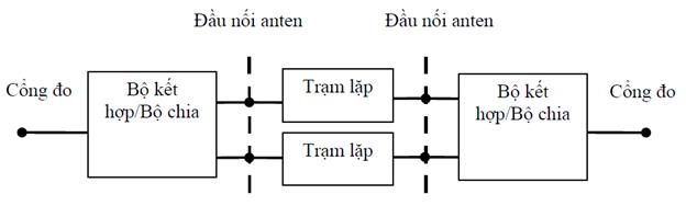
Figure A. 1 - Example of repeater configuration
 Appendix B
(Reference)
Requirements for environmental conditions
The following environmental conditions are due to Supplier declaration:
- Air pressure: lowest and highest;
- Temperature: lowest and highest;
- Relative humidity: lowest and highest;
- Power source: upper and lower limits of voltage.
B.1. Normal test environment
When the normal test environment is specified, testing shall be performed within the lowest and highest limits of the conditions shown in Table B.1.
Table B.1 – Limits of conditions for normal test environment
Condition | Lowest | Highest |
Air pressure | 86 kPa | 106 kPa |
Temperature | 15 0 C | 30 0 C |
Relative humidity | 20 % | 85 % |
Power supply | Nominal, as declared by the manufacturer | |
Vibration | Trivial | |
The above ranges of atmospheric pressure, temperature and humidity correspond to the maximum variations expected in the uncontrolled environment of a test laboratory. If it is not possible to maintain these parameters within the specified limits, the actual values shall be recorded in the test report.
NOTE: For example, radiated emission measurements in an extended field test point.
B.2. Critical test environment
The manufacturer must declare one of the following conditions :
1) The type of equipment representing the equipment to be tested, as defined in TCVN 7921 -3-3.
2) The type of equipment representing the equipment to be tested, as defined in TCVN 7921 -3-4.
3) For equipment not complying with the types already mentioned, the relevant types in TCVN 7921 series for temperature, humidity and vibration, must be declared.
NOTE: Performance degradation due to environmental conditions outside the standard operating conditions is not measured in this standard. Such environmental conditions may be specified and measured separately.
B.2.1. Critical temperature
When a critical temperature test environment is specified for a test, the test shall be performed at the manufacturer's published minimum and maximum standard operating temperatures. for the equipment to be tested.
Lowest temperature:
The test shall be performed with equipment and environmental test methods including the required environmental phenomena affecting the equipment, following the test procedure of TCVN 7699-2-1.
Maximum temperature:
The test shall be performed with equipment and environmental test methods including the required environmental phenomena affecting the equipment, following the test procedure of TCVN 7699-2-2.
NOTE: It is recommended that the equipment be fully functional before being brought to its lower operating temperature.
B.3. Vibration
When vibration conditions are specified for a test, the test shall be performed while the equipment is subjected to vibration in a sequence determined by the manufacturer's declaration for the test equipment. The test shall use environmental test equipment and methods including the environmental phenomena required to be applied to the equipment, in accordance with the test procedure of TCVN 7699-2-6. Other environmental conditions shall be within the range specified in B.1.
NOTE: Higher vibration levels may cause excessive physical stress within the equipment after an extended test. The test team should only vibrate the equipment during RF measurements.
Appendix C
(Reference)
Repeater device measurement diagram
C.1. Maximum output power

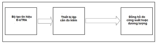
Figure C. 1 – Maximum power measurement system diagram
Note that the repeater is a two-way device. The signal generator may need protection.
C.2. Out-of-band gain
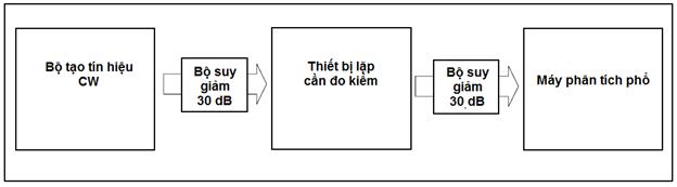
Figure C. 2 – Out-of-band gain measurement system diagram
Note that the repeater is a two-way device. The signal generator may need protection.
C.2. Unwanted emissions: Unwanted emissions operating band
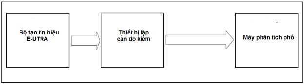
Figure C. 3 – Schematic diagram of unwanted emission measurement system: Unwanted emissions operating band
Note that the repeater is a two-way device. The signal generator may need protection.
C.4. Unwanted emissions: Spurious emissions
Figure C. 4 – Schematic diagram of unwanted emission measurement system: Spurious emission
Note that the repeater is a two-way device. The signal generator may need protection.
C.5. Input intermodulation
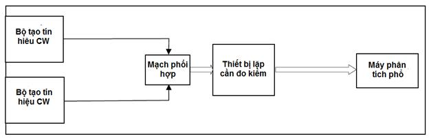
Figure C. 5 – Input intermodulation measurement system diagram
Note that the repeater is a two-way device. The signal generator may need protection.
C.6. Output intermodulation
![]()
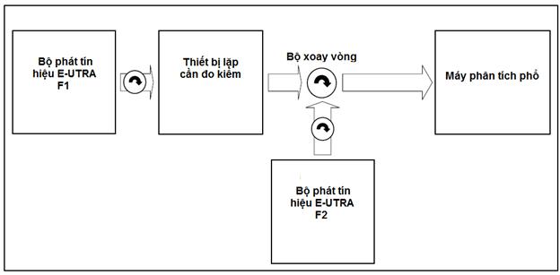
Figure C. 6 – Schematic diagram of the output intermodulation measurement system
Note that the repeater is a two-way device. The signal generator may need protection.
C.7. Neighbouring channel compression factor
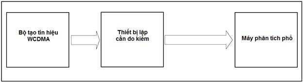
Figure C. 7 – Diagram of neighbouring channel compression ratio measurement system
Note that the repeater is a two-way device. The signal generator may need protection.
Appendix D
(Reference)
Repeater device reference input signal
The reference channels or test models generating the repeater reference input signal shall meet the spectral purity requirements specified in Table D.1. Where:
- The reference spectral density is taken from a 200 kHz carrier center frequency with an integration bandwidth of 30 kHz.
- ∆f is the deviation from the nominal passband edge frequency and the nominal -3 dB point of the measuring filter closest to the carrier frequency.
- f_offset is the offset from the nominal passband edge frequency to the center of the measurement filter.
- f_offsetmax is the frequency offset of the frequency that lies outside the 10 MHz operating bandwidth of the repeater.
- ∆f max is equal to f_offset max minus half the bandwidth of the measurement filter.
- Minimum spectral density suppression relative to the reference spectral density.
Table D. 1 – Repeater reference input signal spectral purity requirements SEQ Bảng_D. \* ARABIC
Frequency deviation of the -3 dB measurement filter point, ∆f | Frequency offset of the center frequency of the measuring filter, f_offset | Minimum requirements | Measurement bandwidth |
0 MHz ≤ ∆f < 0.15 MHz | 0.015 MHz ≤ f_offset < 0.165 MHz | -40 + 20×(f_offset – 0.015) dBc | 30kHz |
0.15 MHz ≤ ∆f < 0.2 MHz | 0.165 MHz ≤ f_offset < 0.215 MHz | -37 dBc | 30kHz |
0.2 MHz ≤ ∆f < 1 MHz | 0.215 MHz ≤ f_offset < 1.015 MHz | -94 dBm - 15×(f_offset -0.215) dB | 30kHz |
1.015 MHz ≤ f_offset < 1.5MHz | -106 dBm | 30kHz | |
1 MHz ≤ ∆f < 2.8 MHz | 1.5 MHz ≤ f_offset < 2.85 MHz | -78 dBm | 1 MHz |
2.8 MHz ≤ ∆f < ∆f max | 2.85 MHz ≤ f_offset < f_offset max | -80 dBm | 1 MHz |
NOTE: The units of measurement for frequency and bandwidth must be MHz. | |||
Appendix E
(Regulation)
E-UTRA FDD Mobile Repeater Station Equipment
TT | Product name, goods according to QCVN | HS Code | Product description, goods |
01 | E-UTRA FDD Repeater | 8517.62.59 | Equipment with the function of receiving and retransmitting signals of mobile information networks using E-UTRA FDD technology with or without integrating one or more of the following functions: - GSM mobile information repeater; - W-CDMA FDD mobile information repeater; - Fifth generation mobile communication (5G). |
References
[1] ETSI EN 301 908-1 V15.1.1 (2021-09): "IMT cellular networks; Harmonized Standard covering the essential requirements of article 3.2 of the Directive 2014/53/EU; Part 1: Introduction and common requirements".
[2] ETSI EN 301 908-15 V15.1.1 (2020-01): "IMT cellular networks; Harmonized EN covering the essential requirements of article 3.2 of the Directive 2014/53/EU; Part 15: Evolved Universal Terrestial Radio Access (E-UTRA FDD) Repeaters.
You are not logged in.
This feature is available to Advanced account holders. Please log in to access detailed information on Related documents.
If you do not have an account, please register here!
VIETNAMESE DOCUMENTS
This utility is available to subscribers only. Please log in to a subscriber account to download. Don’t have an account? Register here
This utility is available to subscribers only. Please log in to a subscriber account to download. Don’t have an account? Register here
ENGLISH DOCUMENTS
This utility is available to subscribers only. Please log in to a subscriber account to download. Don’t have an account? Register here

