Circular 15/2023/TT-BTTTT National technical regulations on evolved universal terrestrial radio access (E-UTRA) base station (BS) - Radio access
- Summary
- Content
- Status
- Vietnamese
- Related documents
- Diagram
- Download
Please log in to your Advanced Package to view the full text. Do not have an account yet? Register here.
Please log in to use this function
Please log in to use this function
ATTRIBUTE
| Issuing body: | Ministry of Information and Communications | Effective date: |
Known
Please log in to a subscriber account to use this function. Don’t have an account? Register here |
| Official number: | 15/2023/TT-BTTTT | Signer: | Nguyen Manh Hung |
| Type: | Circular | Expiry date: | Updating |
| Issuing date: | 24/11/2023 | Effect status: |
Known
Please log in to a subscriber account to use this function. Don’t have an account? Register here |
| Fields: | Information - Communications |
The Effect status of this document is known.This feature is available to Advanced account holders. Please log in to a subscriber account to view Effect status. Don’t have an account? Register here
|
THE MINISTRY OF INFORMATION AND COMMUNICATIONS ------------------------- No. 15/2023/TT-BTTTT |
THE SOCIALIST REPUBLIC OF VIETNAM ------------------------- Hanoi, November 24, 2023 |
CIRCULAR
Promulgation of "National technical regulations on evolved universal terrestrial radio access (E-UTRA) base station (BS) - Radio access"
Pursuant to the Law on Standards and Technical Regulations dated June 29, 2006;
Pursuant to the Telecommunications Law dated November 23, 2009;
Pursuant to the Law on Radio Frequency dated November 23, 2009 and the Law amending and supplementing a number of articles of the Law on Radio Frequency dated November 9, 2022;
Pursuant to Decree No. 127/2007/ND-CP dated August 1, 2007 of the Government detailing and guiding the implementation of a number of articles of the Law on Standards and Technical Regulations and Decree No. 78/2018/ ND-CP dated May 16, 2018 of the Government amending and supplementing a number of articles of Decree No. 127/2007/ND-CP dated August 1, 2007 of the Government detailing the implementation of a number of articles of the Law Standards and Technical Regulations;
Pursuant to Decree No. 48/2022/ND-CP dated July 26, 2022 of the Government regulating the functions, tasks, powers and organizational structure of the Ministry of Information and Communications;
At the request of the Director of the Department of Science and Technology,
The Minister of Information and Communications promulgates a Circular regulating National technical regulations on evolved universal terrestrial radio access (E-UTRA) base station (BS) - Radio access.
Article 1. Issued together with this Circular is the National technical regulations on evolved universal terrestrial radio access (E-UTRA) base station (BS) - Radio access (QCVN 110:2023/BTTTT).
Article 2. This Circular takes effect from July 1, 2024 and replaces Circular No. 24/2017/TT-BTTTT dated January 17th, 2017 of the Minister of Information and Communications issued "National technical regulations on evolved universal terrestrial radio access (E-UTRA) base station (BS) - Radio access".
Article 3. Chief of Office, Director of the Department of Science and Technology, Heads of agencies and units under the Ministry of Information and Communications, Directors of Departments of Information and Communications of provinces and centrally run cities and organizations, relevant individuals are responsible for implementing this Circular./ .
|
|
MINISTER
Nguyen Manh Hung |

SOCIALIST REPUBLIC OF VIETNAM
QCVN 110:2023/BTTTT
NATIONAL TECHNICAL REGULATIONS ON EVOLVED UNIVERSAL TERRESTRIAL RADIO ACCESS (E-UTRA)
BASE STATION (BS) - RADIO ACCESS
HANOI - 2023
Preface
QCVN 110:2023/BTTTT replaces QCVN 110:2017/BTTTT.
QCVN 110:2023/BTTTT compiled by the Institute of Postal Science and Technology, approved by the Department of Science and Technology, appraised by the Ministry of Science and Technology, and issued by the Ministry of Information and Communications together with Circular No.15/2023/TT-BTTTT dated November, 24th, 2023.
National technical regulation
on Evolved Universal Terrestrial Radio Access (E-UTRA)
Base Stations (BS) - Radio Access
1. GENERAL PROVISIONS
1.1. Adjustment range
This regulation stipulates the technical requirements for E-UTRA base station equipment operating in all or part of any frequency band specified in Table 1.
Table 1 - Frequency bands of E-UTRA base station equipment
|
E-UTRA band |
Transmission direction |
Base station device frequency band E-UTRA |
Duplex mode |
|
1 |
Receive |
2 110 MHz to 2 170 MHz |
FDD |
|
Transmit |
1 920 MHz to 1 980 MHz |
||
|
3 |
Receive |
1 805 MHz to 1 880 MHz |
FDD |
|
Transmit |
1 710 MHz to 1 785 MHz |
||
|
5 |
Receive |
869 MHz to 880 MHz |
FDD |
|
Transmit |
824 MHz to 835 MHz |
||
|
8 |
Receive |
925 MHz to 960 MHz |
FDD |
|
Transmit |
880 MHz to 915 MHz |
||
|
28 |
Receive |
758 MHz to 788 MHz |
FDD |
|
Transmit |
703 MHz to 733 MHz |
||
|
40 |
Transmit and receive |
2 300 MHz to 2 400 MHz |
TDD |
|
41 |
Transmit and receive |
2 500 MHz to 2 690 MHz |
TDD |
HS code of E-UTRA base station equipment specified in Appendix D.
1.2. Applicable subjects
This regulation applies to Vietnamese and foreign organizations and individuals that produce and trade equipment within the scope of this regulation in the territory of Vietnam.
1.3. References
ETSI TS 136 141 (V15.9.0) (07-2020): "LTE; Evolved Universal Terrestrial Radio Access (E-UTRA); Base Station (BS) conformance testing (3GPP TS 36.141 version 15.9.0 Release 15)".
ETSI TS 125 104 (V15.5.0) (04-2019): "Universal Mobile Telecommunications System (UMTS); Base Station (BS) radio transmission and reception (FDD) (3GPP TS 25.104 version 15.5.0 Release 15)".
ETSI TS 125 105 (V15.0.0) (07-2018): "Universal Mobile Telecommunications System (UMTS); Base Station (BS) radio transmission and reception (TDD) (3GPP TS 25.105 version 15.0.0 Release 15)".
ETSI TS 136 104 (V15.9.0) (07-2020): "LTE; Evolved Universal Terrestrial Radio Access (E-UTRA); Base Station (BS) radio transmission and reception (3GPP TS 36.104 version 15.9.0 Release 15)" .
ETSI TS 125 141 (V15.4.0) (04-2019): "Universal Mobile Telecommunications System (UMTS); Base Station (BS) conformance testing (FDD) (3GPP TS 25.141 version 15.4.0 Release 15)".
ETSI TS 136 211 (V15.9.0) (04-2020): "LTE; Evolved Universal Terrestrial Radio Access (E-UTRA); Physical channels and modulation (3GPP TS 36.211 version 15.9.0 Release 15)".
ETSI EN 301 908-18 (V15.1.1) (September 2021): "IMT cellular networks; Harmonized Standard for access to radio spectrum; Part 18: E-UTRA, UTRA and GSM/EDGE Multi-Standard Radio (MSR) Base Station (BS) Release 15".
ETSI EN 301 893 (V2.1.1) (May 2017): "5 GHz RLAN; Harmonized Standard covering the essential requirements of article 3.2 of Directive 2014/53/EU".
ETSI TS 136 213 (V15.9.0) (04-2020): "LTE; Evolved Universal Terrestrial Radio Access (E-UTRA); Physical layer procedures (3GPP TS 36.213 version 15.9.0 Release 15)".
ETSI TS 136 101 (V15.11.0) (08-2020): "LTE; Evolved Universal Terrestrial Radio Access (E-UTRA); User Equipment (UE) radio transmission and reception (3GPP TS 36.101 version 15.11.0 Release 15)" .
ETSI TR 100 028 (all parts) (V1.4.1): "Electromagnetic compatibility and Radio spectrum Matters (ERM); Uncertainties in the measurement of mobile radio equipment characteristics".
ITU-R SM.329-12 (September 2012): "Unwanted emissions in the spurious domain".
ITU-R SM.1539-1 (November 2002): “Variation of the boundary between the out-of-band and spurious domains required for the application of Recommendations ITU-R SM.1541 and ITU-R SM.329”.
TCVN 7699-2-1 :2007 (IEC 60068-2-1): “Environmental testing - Part 2-1: Tests - Test A: Cold”.
TCVN 7699-2-2 :2011 (IEC 60068-2-2): “Environmental testing - Part 2-2: Tests - Test B: Dry heat”.
TCVN 7699-2-6 :2009 (IEC 60068-2-6): “Environmental testing - Part 2-6: Tests - Fc test: Vibration (Sinusoidal)”.
TCVN 7921-3-3 :2014 (IEC 60721-3-3): “Classification of environmental conditions - Part 3-3: Classification by group of environmental parameters and severity - Stationary use in a location protected from weather details".
TCVN 7921-3-4 :2014 (IEC 60721-3-4): “Classification of environmental conditions - Part 3-4: Classification by groups of environmental parameters and severity - Stationary use in locations not protected from weather".
1.4. Explanation of words
For the purposes of this regulation, the following terms are applied:
1.4.1. Aggregated Channel Bandwidth
RF bandwidth, where a base station transmits and/or receives multiple contiguous aggregated carriers.
NOTE: The unit of measurement for aggregated channel bandwidth is MHz.
1.4.2. Base Station class
Wide coverage base station, medium coverage base station, narrow coverage base station or indoor base station announced by the manufacturer.
1.4.3. Base Station RF Bandwidth
RF bandwidth in which the base station transmits and/or receives one or more carriers in a supported operating frequency band.
NOTE: In single carrier operation, the base station RF bandwidth is equal to the channel bandwidth.
1.4.4. RF Bandwidth edge
The frequency of one of the edges of the base station's RF bandwidth.
NOTE: The base station RF bandwidth separates the base station RF bandwidth edges.
1.4.5. Carrier
The modulated waveform is transmitted on E-UTRA or UTRA (WCDMA) physical channels.
1.4.6. Carrier aggregation
Aggregation of two or more component carriers to support wider transmission bandwidths.
1.4.7. Carrier aggregation band
A collection of one or more operating frequency bands in which the aggregated carriers share a specific set of technical requirements.
NOTE: The carrier aggregation band(s) for an E-UTRA base station are declared by the manufacturer and specified in ETSI TS 136 101.
1.4.8. Channel bandwidth
The RF bandwidth supports a single E-UTRA RF carrier with the transmit bandwidth configured in the uplink or downlink of a cell.
NOTE: The unit of measurement for channel bandwidth is MHz, and is intended as a reference for the RF requirements of the transmitter and receiver.
1.4.9. Channel edge
The lowest or highest frequency of the E-UTRA carrier.
NOTE: Channel bandwidth separates channel edges.
1.4.10. Contiguous carriers
Two or more carriers are configured within a spectrum block, where there is no set of coexistence-based RF requirements for uncoordinated operation within this spectrum block.
1.4.11. Contiguous spectrum
The spectrum consists of a contiguous block of the spectrum without component block guard intervals.
1.4.12. Downlink operating band
Part of the operating band is used for the downlink (BS transmit).
1.4.13. Home Base Station
The base station has the characteristics to meet the requirements of femtocell scenarios.
1.4.14. Inter RF Bandwidth gap
The frequency guard interval between two consecutive base station RF bandwidths is set within the two supported operating bands.
1.4.15. Inter-band carrier aggregation
Carrier aggregation of component carriers in different operating bands.
NOTE: The carriers aggregated in each frequency band may or may not be adjacent.
1.4.16. Inter-band gap
The frequency guard interval between two consecutive operating bands is supported.
1.4.17. Intra-band contiguous carrier aggregation
Adjacent carriers are aggregated within the same operating frequency band.
1.4.18. Intra-band non-contiguous carrier aggregation
Non-adjacent carriers are aggregated within the same operating frequency band.
1.4.19. Local Area Base Station
The base station is characterized to meet the requirements of picocell scenarios with a minimum coupling loss from a BS to the UE of 45 dB.
1.4.20. Lower sub-block edge
Frequency at the lower boundary of a component block.
NOTE: Used as a frequency reference point for both transmitter and receiver requirements.
1.4.21. Maximum Base Station RF Bandwidth
The maximum RF bandwidth supported by a BS in each supported operating band.
1.4.22. Maximum output power
The average power level per base station carrier measured at the antenna connector under specified reference conditions.
1.4.23. Maximum Radio Bandwidth
The maximum frequency difference between the upper edge of the highest used carrier and the lower edge of the lowest used carrier.
1.4.24. Maximum throughput
Maximum achievable throughput for a reference measurement channel.
1.4.25. Mean power
Power measured at the channel bandwidth of the carrier over a measurement period of at least one time slot (1 ms) unless otherwise declared when applicable to E-UTRA transmission.
1.4.26. Medium Range Base Station
The base station is characterized to meet the requirements of microcell scenarios with a minimum coupling loss from a BS to the UE of 53 dB.
1.4.27. Multi-band Base Station
The base station has a transmitter and/or receiver capable of simultaneously processing two or more carriers in common enabled RF components, where at least one carrier is configured at a different frequency band (which is not a sub-band or alternative band of another operating band) with the remaining carrier(s).
1.4.28. Multi-band receiver
The receiver is capable of simultaneously processing two or more carriers in common enabled RF components, where at least one carrier is configured at another frequency band (which is not a sub-band or alternative frequency band of a different operating band) to the remaining carrier(s).
1.4.29. Multi-band transmitter
The transmitter is capable of simultaneously processing two or more carriers in common enabled RF components, where at least one carrier is configured at a different frequency band (which is not a sub-band or alternative frequency band of a different operating band) to the remaining carrier(s).
1.4.30. Multi-carrier transmission configuration
An aggregation of one or more contiguous carriers, in which the base station can simultaneously transmit these carriers according to the manufacturer's specifications.
1.4.31. Contiguous spectrum
The spectrum consists of two or more component blocks, which are separated by component block guard intervals.
1.4.32. Operating band
The frequency range (paired or unpaired) is regulated by a specific set of technical requirements in which E-UTRA operates.
NOTE: The operating band(s) of an E-UTRA BS are declared by the manufacturer as specified in Table 1 . E-UTRA's operating bands are numbered with Arabic numerals, while the corresponding UTRA operating bands are numbered with Roman numerals.
1.4.33. Output power
The average power of a base station carrier, delivered to a load whose resistance is equal to the transmitter's nominal load impedance.
1.4.34. Rated output power
The base station's nominal output power is the average power level per carrier declared by the manufacturer as available at the antenna connector.
1.4.35. Rated total output power
The average power level declared by the manufacturer is available at the antenna connector.
1.4.36. Resource block
The physical resource consists of a number of symbols in the time domain and a number of consecutive subcarriers spanning 180 kHz in the frequency domain.
1.4.37. Sub - block
The spectrum block is allocated contiguously for transmitting and receiving within the same base station.
NOTE: There can be multiple sub-block patterns within a base station RF bandwidth.
1.4.38. Sub-block bandwidth
Bandwidth of a component block.
1.4.39. Sub-block gap
Frequency guard interval between two consecutive blocks of components within a base station RF bandwidth, where the RF requirements within the guard interval are based on coexistence for uncoordinated operation.
1.4.40. Synchronized operation
TDD operates in two different systems, in which the uplink and downlink do not appear simultaneously.
1.4.41. Throughput
Number of useful bits received per second on a standard measurement channel under specified standard conditions.
1.4.42. Total RF Bandwidth
Maximum sum of base station RF bandwidths in supported operating bands.
1.4.43. Transmission bandwidth
Instantaneous broadcast bandwidth from a UE or BS, the measurement unit is the resource block.
1.4.44. Transmission bandwidth configuration
The highest transmission bandwidth allocated to the uplink or downlink within a specified channel bandwidth, the unit of measurement is the resource block.
1.4.45. Transmitter OFF period
Period of time a BS transmitter is not allowed to transmit.
1.4.46. Transmitter ON period
The time period during which a BS transmitter transmits data and/or standard symbols, for example data component frames or DwPTS.
1.4.47. Transmitter transient period
The time cycle the generator switches from OFF cycle to ON cycle or vice versa.
1.4.48. Unsynchronized operation
TDD operation in two different systems, where synchronous operating conditions are not met.
1.4.49. Uplink operating band
The portion of the operating band assigned to the uplink (receiving BS).
1.4.50. Upper sub-block edge
Frequency at the upper boundary of a component block.
NOTE: This frequency is used as a frequency reference point for transmitter and receiver requirements.
1.4.51. Wide area base station
The base station has the characteristics of meeting macrocell requirements with a minimum coupling loss from a BS to a UE of 70 dB.
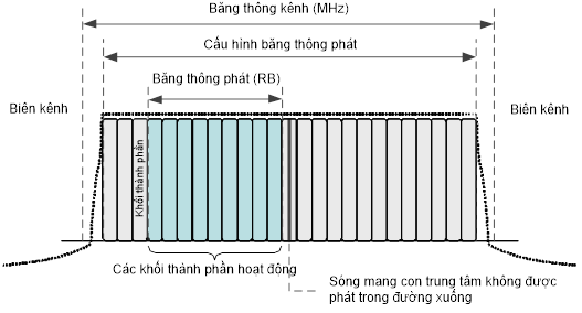
Figure 1 – Channel bandwidth and transmit bandwidth configuration for an E-UTRA carrier
Figure 2 illustrates the aggregated channel bandwidth for in-band contiguous carrier aggregation.
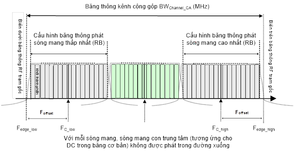
Figure 2 – Aggregated channel bandwidth for intra-band carrier aggregation
The following definitions are applied:
- The lower edge of the cumulative channel bandwidth BWChannel_CA is Fedge_low = FC_low – Foffset ;
- The edge on the cumulative channel bandwidth BWChannel_CA is Fedge_high = FC_high + Foffset;
- Cumulative channel bandwidth BWChannel_CA = Fedge_high – Fedge_low [MHz].
Figure 3 illustrates the component block bandwidth for a BS operating in a non-adjacent spectrum.
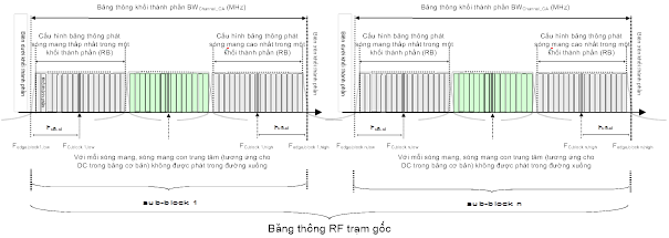
Figure 3 – Component block bandwidth for intra-band non-contiguous spectrum
The following definitions are also applied in this regulation:
- The component block lower edge of the component block bandwidth Fedge,block,low = FC,block,low – Foffset;
- Edge on component block of component block bandwidth Fedge,block,high = FC,block,high + Foffset;
- Cumulative channel bandwidth BWChannel ,block = Fedge ,block, high – Fedge ,block, low (MHz) .
Table 2 defines the Foffset, where BWChannel is specified in Table 5.6-1 of ETSI TS 136 141.
Table 2 – Definitions for Foffset
|
The highest or lowest channel bandwidth (MHz) |
Foffset t (MHz) |
|
5, 10, 15, 20 |
BWChannel /2 |
|
NOTE 1: The Foffset of each base station RF bandwidth edge/component block edge is calculated separately. The BWChannel_CA / BWChannel ,block values for the UE and BS are the same if the bandwidths of the highest and lowest component carriers are identical. |
|
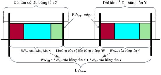
Figure 4 – Maximum radio bandwidth BWmax and total RF bandwidth BWtot multi-band base station
1.5. Symbol
For the purposes of this regulation, the following symbols are applied:
|
BRFBW |
The maximum base station RF bandwidth is at the lower end of the supported frequency range in the operating band |
|
BWChannel |
Channel bandwidth |
|
BWChannel, block |
Component block bandwidth, unit is Mhz. BWChannel,block = Fedge,block,high - Fedge,block,low |
|
BWConfig |
Configure the transmit bandwidth, in Mhz, where BWConfig = N RB x 180 kHz for uplink and, BWConfig = 15 kHz + N RB x 180 kHz for downlink |
|
BWmax |
Maximum radio bandwidth |
|
BWtot |
Total RF bandwidth |
|
CPICH Êc |
Common pilot channel coding capacity (in adjacent channel) |
|
CRS Ês |
Reference signal power received on the resource element |
|
f |
Frequency |
|
Df |
The distance between the channel edge frequency and the nominal -3 dB point of the measurement filter closest to the carrier frequency |
|
Df max |
The maximum value of Df used to determine the requirement |
|
FC |
Carrier center frequency |
|
FC, block, high |
Highest carrier center frequency transmitted/received in a component block |
|
FC, block, low |
Highest carrier center frequency transmitted/received in a component block |
|
FC_high |
Carrier center frequency of the highest carrier, unit is MHz |
|
FC_low |
Carrier center frequency of the lowest carrier, unit is MHz |
|
Fedge_low |
The lower edge of the cumulative channel bandwidth, in MHz, Fedge_low = FC_low – Foffset |
|
Fedge_high |
The upper edge of the cumulative channel bandwidth, in MHz, Fedge_high = FC_high – Foffset |
|
Fedge,block,low |
The edge below the component block, where Fedge,block,low = FC,block,low – Foffset |
|
Fedge,block,high |
Edge on the component block, where Fedge,block,high = FC,block,high – Foffset |
|
Foffset |
Frequency offset from FC_high to edge above base station RF bandwidth or from FC,block,high to edge above component block, FClow to edge below base station RF bandwidth or from FC,block,low to edge under the component block |
|
Ffilter |
Filter center frequency |
|
f interferer |
Center frequency of the interfering signal |
|
f_offset |
The distance between the channel edge frequency and the measurement filter center frequency |
|
f_offset max |
The maximum value of f_offset is used to determine the request |
|
FUL_low |
Lowest frequency of uplink operating band (see Table 1) |
|
FUL_high |
Highest frequency of uplink operating band (see Table 1) |
|
Ioh |
The total received power density does not include the signal of the indoor base station itself |
|
Iuant |
E-Node B internal logical interface between the processing specific O&M function and the RET antennas and the E-Node B TMAs control function block |
|
NRB |
Configure broadcast bandwidth, units are components of component blocks (Resource Blocks) |
|
|
Number of downlink resource blocks |
|
|
Number of subcarriers in a resource block, |
|
p |
Number of antenna ports |
|
(Pi) |
Power of the signal at the antenna connector i |
|
(Ps) |
Total power for all antenna connectors |
|
P10MHz |
Maximum output power at 10 MHz |
|
PEM ,N |
Declared emission level for channel N |
|
PEM,B32,ind |
Declared emission level at band 32, ind = a, b, c, d, e |
|
Pmax,c |
Maximum carrier output power |
|
Pout |
Output capacity |
|
Prated,c |
Nominal output power (on carrier) |
|
PREFSENS |
Standard sensitivity power level |
|
TRFBW |
Maximum base station RF bandwidth at the top of the supported frequency range in the operating band |
|
Wgap |
The component block guard interval or associated bandwidth guard interval size |
1.6. Abbreviations
For the purposes of this regulation, the following abbreviations are applied:
|
ACLR |
Adjacent Channel Leakage Ratio |
|
|
ACS |
Adjacent Channel Selectivity |
|
|
ATT |
Attenuator |
|
|
AWGN |
Additive White Gaussian Noise |
|
|
B |
Bottom RF channel |
|
|
BRFBW |
Bottom Radio Frequency channel BandWidth BS |
|
|
BS |
Base Station |
|
|
BTS |
Base Transceiver Station |
|
|
BW |
BandWidth |
|
|
C |
Contiguous |
|
|
CA |
Carrier Aggregation |
|
|
CACLR |
Cumulative ACLR |
|
|
CSG |
Closed Subscriber Group |
|
|
CW |
Continuous Wave |
|
|
DC |
Direct Current |
|
|
DL |
Download Link |
|
|
DTT |
Digital Terrestrial Television |
|
|
DwPTS |
Downlink part of the special subframe |
|
|
EARFCN |
E-UTRA Absolute Radio Frequency Channel Number |
|
|
ERM |
EMC and Radio spectrum Matters |
|
|
E-TM |
E-UTRA Test Model |
|
|
EUT |
Equipment Under Test |
|
|
E-UTRA |
Evolved UMTS Terrestrial Radio Access |
|
|
FDD |
Frequency Division Duplex |
|
|
FRC |
Fixed Reference Channel |
|
|
GSM |
General System for Mobile communications |
|
|
IMT |
International Mobile Telecommuni-cations |
|
|
LTE |
Long Term Evolution |
|
|
M |
Middle RF channel |
|
|
MBT |
Multi-Band Testing |
|
|
MS |
Mobile Station |
|
|
MSG |
Mobile Standards Group |
|
|
MSR |
Multi-Standard Radio |
|
|
MUE |
Macro UE |
|
|
RAT |
Radio Access Technology |
|
|
RB |
Resource Block |
|
|
RF |
Radio Frequency |
|
|
RFBW |
Radio Frequency BandWidth |
|
|
RMS |
Root Mean Square |
|
|
RRC |
Root Raised Cosine |
|
|
RX |
Receive |
|
|
SBT |
Single Band Testing |
|
|
T |
Top RF channels |
|
|
TDD |
Time Division Duplex |
|
|
TFES |
Task Force for European Standards for IMT |
|
|
TRFBW |
Top Radio Frequency channel BandWidth |
|
|
TX |
Transmit |
|
|
UE |
User Equipment |
|
|
UL |
UpLink |
|
|
UMTS |
Universal Mobile Telecommuni-cations System |
|
|
UTRA |
UMTS Terrestrial Radio Access |
|
2. TECHNICAL REGULATIONS
2.
2.1. Environmental conditions
The technical requirements of this regulation are applied under the operating environment conditions of the equipment announced by the manufacturer. Equipment must fully comply with all technical requirements of this regulation when operating within the boundary limits of the declared operating environmental conditions.
Appendix B guides suppliers on how to declare environmental conditions.
2.2. Technical requirements
2.2.1. General requirements
Device manufacturers must declare:
- Base station operating bands;
- Base station operating bands support carrier aggregation;
- RF configurations are supported as specified in 4.6.8 of ETSI TS 136 141.
For base stations that support multiple operating bands, the testing specified in Article 3 of this regulation must be implemented on each frequency band.
For a BS with a multi-carrier reception configuration, all throughput requirements must be applied to each received carrier. For ACS, blocking, and intermodulation characteristics, the negative offsets of the interfering signal must be relative to the edge on the base station RF bandwidth.
For BSs capable of multi-band operation, the requirements in this regulation are applied to each operating band, unless otherwise specified. In some cases, it may be possible to specify additional or omitted requirements specifically applicable to this BS.
With a BS capable of multi-band operation, it is a combination of different (multi-band or single-band) transmitters/receivers and mapped to one or more antenna ports in different ways, if the bands are transmitted on separate antennas:
- Test single-band ACLR, unwanted emissions in the operating band, transmitter spurious emissions, transmitter intermodulation and receiver spurious emissions applicable to each antenna connector;
- If the BS is configured for single-band operation, the single-band requirements are applied to the antenna connector configured for single-band operation and also to the BS capable of multi-band operation. Single-band requirements are tested independently at an antenna connector configured for single-band operation, while all other antenna connectors are terminated.
For a BS capable of multi-band operation supporting bands for TDD, the RF requirements in this specification assume synchronous operation, where uplinks and downlinks do not occur simultaneously between bands supported operations.
The technical requirements applicable to BS configurations are specified in Appendix A.
2.2.2. Unwanted radiation in the operating frequency band
2.2.2.1. Definition
Unwanted emissions include out-of-band emissions and spurious emissions (Recommendation ITU-R SM.329-12). Out-of-band emissions are unwanted emissions (but do not include spurious emissions), located just outside the channel bandwidth, produced during the modulation process and due to the effects of nonlinearities in the transmitter. The limit of out-of-band emissions of the BS transmitter is determined according to the unwanted emissions in the operating band and the adjacent channel leakage power ratio (ACLR).
Limits for unwanted spurious emissions in the operating bands are specified from 10 MHz below the lowest frequency of each supported downlink operating band to 10 MHz above the highest frequency of each supported operating downlink band is supported (see Table 1).
The requirements are applied to all transmitter types (single carrier or multicarrier) and to all transmit modes selected in accordance with the manufacturer's specifications. Additionally, for a BS operating in multiple bands, these requirements are applied within the RF interband protection interval.
For BSs supporting multicarriers, the unwanted emission requirements are applied to outermost carrier channel bandwidths greater than or equal to 5 MHz.
For a multi-carrier E-UTRA BS configured for intra-band adjacent and non-adjacent carrier aggregation, the above definitions are applied to the lower edge of the transmitted carrier at the lowest carrier frequency and the upper edge of the transmitted carrier at the highest carrier frequency within the specified operating frequency band.
For BSs capable of multi-band operation, where multiple bands are mapped onto separate antenna connectors, single-band requirements are applied but not cumulative estimate of emission limits within the range applies RF interband protection.
2.2.2.2. Limit
For wide coverage BSs, this requirement is applied to outside of the base station RF bandwidth. In addition, this requirement is also applied within any sub-block guard interval for a wide coverage BS operating in a non-adjacent spectrum and within any inter-RF bandwidth guard interval for a wide coverage BS operating in multiple frequency bands.
For medium coverage BSs, this requirement is applied to outside of the base station RF bandwidth. In addition, this requirement is applied within any sub-block guard interval for a medium coverage BS operating in a non-contiguous spectrum and within any inter-RF bandwidth guard interval for a medium coverage BS operating in multiple frequency bands.
For narrow-coverage BSs, this requirement is applied to outside of the base station's RF bandwidth. In addition, this requirement is applied within any sub-block guard interval for a narrow coverage BS operating in a non-contiguous spectrum and within any inter-RF bandwidth guard interval for a narrow coverage BS operating in multiple frequency bands.
Outside the base station RF bandwidth, emissions do not exceed the maximum levels specified in the Tables 3 to 13 and Table 14 to Table 19, in which:
- Df is the distance between the channel edge frequency and the nominal -3 dB point of the measurement filter closest to the carrier frequency;
- f_offset is the distance between the channel edge frequency and the center frequency of the measurement filter;
- f_offsetmax is the offset from the frequency 10 MHz outside the downlink operating band;
- Df max is equal to f_offset max minus half the bandwidth of the measurement filter.
For a BS operating in multiple bands, within any inter-RF bandwidth guard interval with Wgap < 20 MHz, emissions shall not exceed the cumulative sum of the limits specified at the RF bandwidth edges of the base station on each edge of the RF interband guard interval. Limits for RF bandwidth edges are specified in Tables 3 to 5, in which:
- Df is the distance between the base station RF bandwidth edge frequency and the nominal -3 dB point of the measurement filter closest to the base station RF bandwidth edge;
- f_offset is the distance between the RF bandwidth edge frequency of the base station and the center frequency of the measurement filter;
- f_offset max is equal to the RF interband guard interval minus half the measurement filter bandwidth;
- Df max is equal to f_offset max minus half the bandwidth of the measurement filter.
For BSs capable of multi-carrier operation, where multiple frequency bands are mapped onto the same antenna connector, the unwanted emission limits in the operating band also apply within a supported operating band within any transmitted carrier, in cases where there are transmitted carrier(s) in another supported operating band. In this case, the non-cumulative limit applies in the inter-band guard interval between a supported downlink operating band with the transmitted carrier(s) and an externally supported downlink operating band in addition to any transmitted carrier and:
- In case the inter-band guard interval between a supported downlink operating band with the transmitted carrier(s) and a supported downlink operating band outside any transmitted carrier is less than 20 MHz, f_offset max is the offset from the 10 MHz frequency beyond the outermost edges of the supported downlink operating bands and limits unwanted emissions within the operating band where the carriers are transmitted, specified in the tables of this clause, applied on both downlink frequency bands.
- In this case, the limits of unwanted emissions in the operating band of the band, where the transmitted carriers are located, are specified in the tables of this clause for the widest frequency deviation (Df max), applies from 10 MHz below the lowest frequency, up to 10 MHz above the highest frequency of the supported downlink operating band outside any transmitted carrier.
Additionally, within any sub-block guard interval with a BS operating in a non-adjacent spectrum, the measurement results do not exceed the cumulative sum of the limits specified for neighboring sub-blocks on each flank of the component block guard interval. Limits for each component block are specified in the Table 3 to 13 and Table 14 to Table 19, in this case:
- Df is the distance between the component block edge frequency and the nominal -3 dB point of the measurement filter closest to the component block boundary;
- f_offset is the distance between the component block edge frequency and the center frequency of the measurement filter;
- f_offset max is equal to the component block guard interval bandwidth minus half the measurement filter bandwidth;
- Df max is equal to f_offset max minus half the bandwidth of the measurement filter.
2.2.2.2.1. Limiting BS wide coverage in bands 1, 3, 5 and 8
With E-UTRA wide coverage BS operating in bands 1, 3, 5 and 8, emissions do not exceed the limits specified in Table 3 to 5.
Table 3 – Limits for unwanted radiation in band 8 of BS wide coverage for 1.4 MHz channel bandwidth
|
Frequency deviation of the -3 dB point of the measurement filter, Df |
Frequency offset of the center frequency of the measurement filter, f_offset |
Limit (Note 1 and 2) |
Measurement bandwidth |
|
0 MHz ≤ Δf < 0.05 MHz |
0.015 MHz ≤ f_offset < 0.065 MHz |
|
30 kHz |
|
0.05 MHz ≤ Δf < 0.15 MHz |
0.065 MHz ≤ f_offset < 0.165 MHz |
|
30 kHz |
|
0.15 MHz ≤ Δf < 0.2 MHz |
0.165 MHz ≤ f_offset < 0.215 MHz |
-12.5 dBm |
30 kHz |
|
0.2 MHz ≤ Δf < 1 MHz |
0.215 MHz ≤ f_offset < 1.015 MHz |
|
30 kHz |
|
|
1.015 MHz ≤ f_offset < 1.5 MHz |
-24.5 dBm |
30 kHz |
|
1 MHz ≤ Δf ≤ 2.8 MHz |
1.5 MHz ≤ f_offset < 3.3 MHz |
-11.5 dBm |
1MHz |
|
2.8 MHz ≤ Δf ≤ Δfmax |
3.3 MHz ≤ f_offset < f_offsetmax |
-15 dBm |
1MHz |
|
NOTE 1: For a BS supporting non-adjacent spectrum operation in any frequency band, the limit in sub-block guard intervals is calculated as the cumulative sum of the parts from neighboring sub-blocks in each flank of the component block guard interval, where the sections from the far-end component block are scaled according to the measurement bandwidth of the near-end component block. Except, if Df ≥ 10 MHz from both neighboring sub-blocks on each edge of the sub-block guard interval, then the limit within the sub-block guard intervals is -15 dBm/1 MHz. NOTE 2: For BSs supporting multi-band operation with an RF inter-band gap < 20 MHz, the internal limit of the RF inter-band gap is calculated as the cumulative sum of the parts from the neighbouring component blocks or interband RF bandwidth of the base station on each edge of the interband RF guard interval, where the portions from the far component block or base station RF bandwidth are scaled according to the measurement bandwidth of the block near-end component or base station RF bandwidth. |
|||
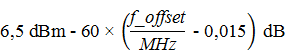
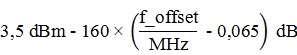
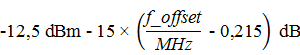
Table 4 – Limits for unwanted radiation in band 8 of BS wide coverage for 3 MHz channel bandwidth
|
Frequency deviation of the -3 dB point of the measurement filter, Df |
Frequency offset of the center frequency of the measurement filter, f_offset |
Limit (Note 1 and 2) |
Measurement bandwidth |
|
0 MHz ≤ Δf < 0.05 MHz |
0.015 MHz ≤ f_offset < 0.065 MHz |
|
30 kHz |
|
0.05 MHz ≤ Δf < 0.15 MHz |
0.065 MHz ≤ f_offset < 0.165 MHz |
|
30 kHz |
|
0.15 MHz ≤ Δf < 0.2 MHz |
0.165 MHz ≤ f_offset < 0.215 MHz |
-12.5 dBm |
30 kHz |
|
0.2 MHz ≤ Δf < 1 MHz |
0.215 MHz ≤ f_offset < 1.015 MHz |
|
30 kHz |
|
|
1.015 MHz ≤ f_offset < 1.5 MHz |
-24.5 dBm |
30 kHz |
|
1 MHz ≤ Δf ≤ 6 MHz |
1.5 MHz ≤ f_offset < 6.5 MHz |
-11.5 dBm |
1MHz |
|
6 MHz ≤ Δf ≤ Δfmax |
6.5 MHz ≤ f_offset < f_offsetmax |
-15 dBm |
1MHz |
|
NOTE 1: For a BS supporting non-adjacent spectrum operation in any frequency band, the limit in sub-block guard intervals is calculated as the cumulative sum of the parts from neighboring sub-blocks in each flank of the component block guard interval, where the sections from the far-end component block are scaled according to the measurement bandwidth of the near-end component block. Except, if Df ≥ 10 MHz from both neighboring sub-blocks on each edge of the sub-block guard interval, then the limit within the sub-block guard intervals is -15 dBm/1 MHz. NOTE 2: For BSs supporting multi-band operation with an RF inter-band gap < 20 MHz, the internal limit of the RF inter-band gap is calculated as the cumulative sum of the parts from the neighbouring component blocks or interband RF bandwidth of the base station on each edge of the interband RF guard interval, where the portions from the far component block or base station RF bandwidth are scaled according to the measurement bandwidth of the block near-end component or base station RF bandwidth. |
|||
Table 5 – Limits for unwanted radiation in bands 1, 3, 5 and 8 of BS wide coverage for channel bandwidths of 5, 10, 15 and 20 MHz
|
Frequency deviation of the -3 dB point of the measurement filter, Df |
Frequency offset of the center frequency of the measurement filter, f_offset |
Limit (Note 1, 2 and 3) |
Measurement bandwidth |
|
0 MHz ≤ Δf < 0.2 MHz |
0.015 MHz ≤ f_offset < 0.215 MHz |
-12.5 dBm |
30 kHz |
|
0.2 MHz ≤ Δf < 1 MHz |
0.215 MHz ≤ f_offset < 1.015 MHz |
|
30 kHz |
|
1.015 MHz ≤ f_offset < 1.5 MHz |
-24.5 dBm |
30 kHz |
|
|
1 MHz ≤ Δf ≤ minimum (10 Mhz, Δf max ) |
1.5 MHz ≤ f_offset < minimum (10.5 Mhz, Δf_offset max ) |
-11.5 dBm |
1MHz |
|
10 MHz ≤ Δf ≤ Δf max |
10.5 MHz ≤ f_offset < f_offset max |
-15 dBm |
1MHz |
|
NOTE 1: The requirement does not apply when Δf max < 10 MHz. NOTE 2: For BSs supporting non-adjacent spectrum operation in any frequency band, the limit in sub-block guard intervals is calculated as the cumulative sum of the parts from neighboring sub-blocks in each flank of the component block guard interval, where the sections from the far-end component block are scaled according to the measurement bandwidth of the near-end component block. Except, if Df ≥ 10 MHz from both neighboring sub-blocks on each edge of the sub-block guard interval, then the limit within the sub-block guard intervals is -15 dBm/1 MHz. NOTE 3: For BSs supporting multi-band operation with an RF inter-band gap < 20 MHz, the internal limit of the RF inter-band gap is calculated as the cumulative sum of the parts from the neighbouring component blocks or interband RF bandwidth of the base station on each edge of the interband RF guard interval, where the portions from the far component block or base station RF bandwidth are scaled according to the measurement bandwidth of the block near-end component or base station RF bandwidth. |
|||
2.2.2.2.2. Limited BS coverage in bands 40 and 41
With E-UTRA wide coverage BS operating in bands 40 and 41, emissions do not exceed the limits specified in Table 6.
Table 6 – Limits on unwanted radiation in bands 40 and 41 of wide coverage BS for channel bandwidths 5, 10, 15 and 20 MHz
|
Frequency deviation of the -3 dB point of the measurement filter, Df |
Frequency offset of the center frequency of the measurement filter, f_offset |
Limit (Note 1, 2 and 3) |
Measurement bandwidth |
|
0 MHz ≤ Δf < 5 MHz |
0.05 MHz ≤ f_offset < 5.05 MHz |
|
100 kHz |
|
5 MHz ≤ Δf < minimum(10 MHz, Δf max ) |
5.05 MHz ≤ f_offset < min (10.05 MHz, f_offset max ) |
-12.5 dBm |
100 kHz |
|
10 MHz ≤ Δf ≤ Δf max |
10.5 MHz ≤ f_offset < f_offset max |
-15 dBm
|
1MHz |
|
NOTE 1: The requirement does not apply when Δf max < 10 MHz. NOTE 2: For BSs supporting non-adjacent spectrum operation in any frequency band, the limit in sub-block guard intervals is calculated as the cumulative sum of the parts from neighboring sub-blocks in each flank of the component block guard interval, where the sections from the far-end component block are scaled according to the measurement bandwidth of the near-end component block. Except, if Df ≥ 10 MHz from both neighboring sub-blocks on each edge of the sub-block guard interval, then the limit within the sub-block guard intervals is -15 dBm/1 MHz. NOTE 3: For BSs supporting multi-band operation with an RF inter-band gap < 20 MHz, the internal limit of the RF inter-band gap is calculated as the cumulative sum of the parts from the neighbouring component blocks or interband RF bandwidth of the base station on each edge of the interband RF guard interval, where the portions from the far component block or base station RF bandwidth are scaled according to the measurement bandwidth of the block near end component or base station RF bandwidth. |
|||
2.2.2.2.3. Limited BS coverage in band 28
With E-UTRA wide coverage BS operating in frequency bands 28, emissions do not exceed the limits specified in Table 7.
Table 7 – Limits on unwanted radiation in band 28 of wide coverage BS for channel bandwidths 5, 10, 15 and 20 MHz
|
Frequency deviation of the -3 dB point of the measurement filter, Df |
Frequency offset of the center frequency of the measuring filter, f_offset |
Limit (Note 1, 2 and 3) |
Measurement bandwidth |
|
0 MHz ≤ Δf < 5 MHz |
0.05 MHz ≤ f_offset < 5.05 MHz |
|
100 kHz |
|
5 MHz ≤ Δf < 10 MHz |
5.05 MHz ≤ f_offset < 10.05 MHz |
-12.5 dBm |
100 kHz |
|
10 MHz ≤ Δf ≤ Δf max |
10.5 MHz ≤ f_offset < f_offset max |
-1 6 dBm
|
1 00k Hz |
|
NOTE 1: The requirement does not apply when Δf max < 10 MHz. NOTE 2: For BSs supporting non-adjacent spectrum operation in any frequency band, the limit in sub-block guard intervals is calculated as the cumulative sum of the parts from neighboring sub-blocks in each flank of the component block guard interval, where the sections from the far-end component block are scaled according to the measurement bandwidth of the near-end component block. Except, if Df ≥ 10 MHz from both neighboring sub-blocks on each edge of the sub-block guard interval, then the limit within the sub-block guard intervals is -1 6 dBm/100 kHz. NOTE 3: For BSs supporting multi-band operation with an RF inter-band gap < 20 MHz, the internal limit of the RF inter-band gap is calculated as the cumulative sum of the parts from the neighbouring component blocks or interband RF bandwidth of the base station on each edge of the interband RF guard interval, where the portions from the far component block or base station RF bandwidth are scaled according to the measurement bandwidth of the block near-end component or base station RF bandwidth. |
|||
2.2.2.2.4. Limit of the narrow BS coverage area
With a narrow BS coverage area, emissions do not exceed the limits specified in Table 8 to 10.
Table 8 – Limits of unwanted radiation in the narrow coverage BS operating band for 1.4 MHz channel bandwidth
|
Frequency deviation of the -3 dB point of the measurement filter, Df |
Frequency offset of the center frequency of the measuring filter, f_offset |
Limit
|
Measurement bandwidth |
|
0 MHz ≤ Δf < 1.4 MHz |
0.05 MHz ≤ f_offset < 1.45 MHz |
|
100 kHz |
|
1.4 MHz ≤ Δf < 2.8 MHz |
1.45 MHz ≤ f_offset < 2.85 MHz |
-29.5 dBm |
100 kHz |
|
2.8 MHz ≤ Δf ≤ Δfmax |
2.85 MHz ≤ f_offset < f_offsetmax |
-31 dBm |
100 kHz |
|
NOTE 1: The requirements for a 1.4 MHz channel bandwidth apply to band 8 only. |
|||
Table 9 – Limits of unwanted radiation in the narrow coverage BS operating band for 3 MHz channel bandwidth
|
Frequency deviation of the -3 dB point of the measurement filter, Df |
Frequency offset of the center frequency of the measurement filter, f_offset |
Limit
|
Measurement bandwidth |
|
0 MHz ≤ Δf < 3 MHz |
0.05 MHz ≤ f_offset < 3.05 MHz |
|
100 kHz |
|
3 MHz ≤ Δf < 6 MHz |
3.05 MHz ≤ f_offset < 6.05 MHz |
-33.5 dBm |
100 kHz |
|
6 MHz ≤ Δf ≤ Δfmax |
6.05 MHz ≤ f_offset < f_offsetmax |
-35 dBm |
100 kHz |
|
NOTE 1: The requirements for a 3 MHz channel bandwidth apply to band 8 only. |
|||
Table 10 – Limits of unwanted radiation in the narrow coverage BS operating band for channel bandwidths of 5, 10, 15 and 20 MHz
|
Frequency deviation of the -3 dB point of the measurement filter, Df |
Frequency offset of the center frequency of the measuring filter, f_offset |
Limit
|
Measurement bandwidth |
|
0 MHz ≤ Δf < 5 MHz |
0.05 MHz ≤ f_offset < 5.05 MHz |
|
100 kHz |
|
5 MHz ≤ Δf < minimum (10 MHz, Δf max ) |
5.05 MHz ≤ f_offset < minimum (10.05 MHz, f_offset max ) |
-35.5 dBm |
100 kHz |
|
10 MHz ≤ Δf ≤ Δf max |
10.05 MHz ≤ f_offset < f_offset max |
-37 dBm (see notes) |
100 kHz |
|
NOTE: The requirement does not apply when Δf max < 10 MHz. |
|||
2.2.2.2.5. Limitation for doctors in the house
With indoor BS, emissions do not exceed the limits specified in Table 11 to 13.
Table 11 – Limits for unwanted radiation in the operating band of the indoor BS for the channel bandwidth 1.4 MHz
|
Frequency deviation of the -3 dB point of the measurement filter, Df |
Frequency offset of the center frequency of the measurement filter, f_offset |
Limit
|
Measurement bandwidth |
|
0 MHz ≤ Δf < 1.4 MHz |
0.05 MHz ≤ f_offset < 1.45 MHz |
|
100 kHz |
|
1.4 MHz ≤ Δf < 2.8 MHz |
1.45 MHz ≤ f_offset < 2.85 MHz |
-34.5 dBm |
100 kHz |
|
2.8 MHz ≤ Δf ≤ Δf max |
3.3 MHz ≤ f_offset < f_offset max |
P -52 dB, 2dBm ≤ P ≤ 20 dBm -50 dBm, P < 2 dBm (see Note 1 ) |
1MHz |
|
NOTE 1: For indoor BS, parameter P is the cumulative maximum power of all transmit antenna ports of the indoor BS. NOTE 2: The requirements for a 1.4 MHz channel bandwidth apply to band 8 only. |
|||
Table 12 – Limits for unwanted radiation in the operating band of the indoor BS for the channel bandwidth 3 MHz
|
Frequency deviation of the -3 dB point of the measurement filter, Df |
Frequency offset of the center frequency of the measurement filter, f_offset |
Limit
|
Measurement bandwidth |
|
0 MHz ≤ Δf < 3 MHz |
0.05 MHz ≤ f_offset < 3.05 MHz |
|
100 kHz |
|
3 MHz ≤ Δf < 6 MHz |
3.05 MHz ≤ f_offset < 6.05 MHz |
-38.5 dBm |
100 kHz |
|
6 MHz ≤ Δf ≤ Δfmax |
6.5 MHz ≤ f_offset < f_offset max |
P -52 dB, 2dBm ≤ P ≤ 20 dBm -50 dBm, P < 2 dBm (see Note 1 ) |
1MHz |
|
NOTE 1: For indoor BS, parameter P is the cumulative maximum power of all transmit antenna ports of the indoor BS. NOTE 2: The requirements for a 3 MHz channel bandwidth apply only to band 8. |
|||
Table 13 – Limits of unwanted radiation in the operating band of the indoor BS for channel 5 bandwidth , 10, 15, 20 MHz
|
Frequency deviation of the -3 dB point of the measurement filter, Df |
Frequency offset of the center frequency of the measurement filter, f_offset |
Limit
|
Measurement bandwidth |
|
0 MHz ≤ Δf < 5 MHz |
0.05 MHz ≤ f_offset < 5.05 MHz |
|
100 kHz |
|
5 MHz ≤ Δf < minimum (10 MHz, Δf max ) |
5.05 MHz ≤ f_offset < minimum (10.05 MHz, f_offset max ) |
-40.5 dBm |
100 kHz |
|
10 MHz ≤ Δf ≤ Δf max |
10.5 MHz ≤ f_offset < f_offset max |
P -52 dB, 2dBm ≤ P ≤ 20 dBm -50 dBm, P < 2 dBm (see Note 1 and 2) |
1MHz |
|
NOTE 1: For indoor BS, parameter P is the cumulative maximum power of all transmit antenna ports of the indoor BS. NOTE 2: The requirement does not apply when Δf max < 10 MHz. |
|||
2.2.2.2.6. Limit for BS average coverage area
The E-UTRA medium coverage BS, emissions do not exceed the maximum levels specified in Table 14 to 19.
Table 14 – Limits of unwanted radiation in the operating band of the average coverage BS for channel bandwidth 1.4 MHz, 31 < Prated,c ≤ 38 dBm
|
Frequency deviation of the -3 dB point of the measurement filter, Df |
Frequency offset of the center frequency of the measurement filter, f_offset |
Limit (Note 1 and 2) |
Measurement bandwidth |
|
0 MHz ≤ Δf < 1.4 MHz |
0.05 MHz ≤ f_offset < 1.45 MHz |
|
100 kHz |
|
1.4 MHz ≤ Δf < 2.8 MHz |
1.45 MHz ≤ f_offset < 2.85 MHz |
P max,c - 53.5 dBm |
100 kHz |
|
2.8 MHz ≤ Δf ≤ Δf max |
2.85 MHz ≤ f_offset < f_offset max |
-25 dBm |
100 kHz |
|
NOTE 1: For a BS supporting non-adjacent spectrum operation in any frequency band, the test requirement within the sub-block guard intervals is calculated as the cumulative sum of the parts from neighboring sub-blocks in each flank of the interval protects the component block. Except, if Df ≥ 10 MHz from both neighboring sub-blocks on each edge of the sub-block guard interval, where the measurement requirement within the sub-block guard intervals is -25 dBm/100 kHz. NOTE 2: For BSs supporting multi-band operation with an RF inter-band gap < 20 MHz, the test requirement within the RF inter-band gap is calculated as the cumulative sum of the parts from the neighboring component block or interband RF of the base station on each edge of the interband RF guard interval. NOTE 3 : The requirements for a 1.4 MHz channel bandwidth apply to band 8 only. |
|||
Table 15 – Limits of unwanted radiation in the average coverage BS operating band for channel bandwidth 1.4 MHz, P max,c ≤ 3 1 dBm
|
Frequency deviation of the -3 dB point of the measurement filter, Df |
Frequency offset of the center frequency of the measurement filter, f_offset |
Limit (Note 1 and 2) |
Measurement bandwidth |
|
0 MHz ≤ Δf < 1.4 MHz |
0.05 MHz ≤ f_offset < 1.45 MHz |
|
100 kHz |
|
1.4 MHz ≤ Δf < 2.8 MHz |
1.45 MHz ≤ f_offset < 2.85 MHz |
-22.5 dBm |
100 kHz |
|
2.8 MHz ≤ Δf ≤ Δf max |
2.85 MHz ≤ f_offset < f_offset max |
-25 dBm |
100 kHz |
|
NOTE 1: For a BS supporting non-adjacent spectrum operation in any frequency band, the test requirement within the sub-block guard intervals is calculated as the cumulative sum of the parts from neighboring sub-blocks in each flank of the interval protects the component block. Except, if Df ≥ 10 MHz from both neighboring sub-blocks on each edge of the sub-block guard interval, where the measurement requirement within the sub-block guard intervals is -25 dBm/100 kHz . NOTE 2: For BSs supporting multi-band operation with an RF inter-band gap < 20 MHz, the test requirement within the RF inter-band gap is calculated as the cumulative sum of the parts from the neighboring component block or interband RF of the base station on each edge of the interband RF guard interval. NOTE 3: The requirements for a 1.4 MHz channel bandwidth apply to band 8 only. |
|||
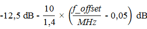
Table 16 – Limits of unwanted radiation in the operating band of the average coverage BS for channel bandwidth 3 MHz, 31 < Pmax,c ≤ 38 dBm
|
Frequency deviation of the -3 dB point of the measurement filter, Df |
Frequency offset of the center frequency of the measurement filter, f_offset |
Limit (Note 1 and 2) |
Measurement bandwidth |
|
0 MHz ≤ Δf < 3 MHz |
0.05 MHz ≤ f_offset < 3.06 MHz |
|
100 kHz |
|
3 MHz ≤ Δf < 6 MHz |
3.05 MHz ≤ f_offset < 6.05 MHz |
Pmax,c - 57.5 dBm |
100 kHz |
|
6 MHz ≤ Δf ≤ Δfmax |
6.05 MHz ≤ f_offset < f_offset max |
smallest (Pmax,c - 59 dB, -25 dBm) |
100 kHz |
|
NOTE 1: For a BS supporting non-adjacent spectrum operation in any frequency band, the test requirement within the sub-block guard intervals is calculated as the cumulative sum of the parts from neighboring sub-blocks in each flank of the interval protects the component block. Except, if Df ≥ 10 MHz from both neighboring sub-blocks on each edge of the sub-block guard interval, where the test requirement within the sub-block guard intervals is minimum (Pmax,c - 59 dB, -25 dBm)/100 kHz. NOTE 2: For BSs supporting multi-band operation with an RF inter-band gap < 20 MHz, the test requirement within the RF inter-band gap is calculated as the cumulative sum of the parts from the neighboring component block or interband RF of the base station on each edge of the interband RF guard interval. NOTE 3: The requirements for a 3 MHz channel bandwidth apply only to band 8. |
|||
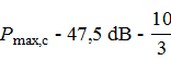
Table 17 – Limits of unwanted radiation in the average coverage BS operating band for channel bandwidth 3 MHz, P max,c ≤ 3 1 dBm
|
Frequency deviation of the -3 dB point of the measurement filter, Df |
Frequency offset of the center frequency of the measurement filter, f_offset |
Limit (Note 1 and 2) |
Measurement bandwidth |
|
0 MHz ≤ Δf < 3 MHz |
0.05 MHz ≤ f_offset < 3.05 MHz |
|
100 kHz |
|
3 MHz ≤ Δf < 6 MHz |
3.05 MHz ≤ f_offset < 6.05 MHz |
-26.5 dBm |
100 kHz |
|
6 MHz ≤ Δf ≤ Δfmax |
6.05 MHz ≤ f_offset < f_offset max |
-28 dBm |
100 kHz |
|
NOTE 1: For a BS supporting non-adjacent spectrum operation in any frequency band, the test requirement within the sub-block guard intervals is calculated as the cumulative sum of the parts from neighboring sub-blocks in each flank of the interval protects the component block. Except, if Df ≥ 10 MHz from both neighboring sub-blocks on each edge of the sub-block guard interval, where the measurement requirement within the sub-block guard intervals is -28 dBm/100 kHz. NOTE 2: For BSs supporting multi-band operation with an RF inter-band gap < 20 MHz, the test requirement within the RF inter-band gap is calculated as the cumulative sum of the parts from the neighboring component block or interband RF of the base station on each edge of the interband RF guard interval. NOTE 3: The requirements for a 3 MHz channel bandwidth apply only to band 8. |
|||
Table 18 – Limits of unwanted radiation in the operating band of the average coverage BS for channel bandwidths 5, 10, 15 and 20 MHz, 31 < P max,c ≤ 38 dBm
|
Frequency deviation of the -3 dB point of the measurement filter, Df |
Frequency offset of the center frequency of the measurement filter, f_offset |
Limit (Note 1 and 3) |
Measurement bandwidth |
|
0 MHz ≤ Δf < 5 MHz |
0.05 MHz ≤ f_offset < 5.05 MHz |
|
100 kHz |
|
5 MHz ≤ Δf < minimum (10 MHz, Δf max ) |
5.05 MHz ≤ f_offset < minimum (10.05 MHz, f_offset max ) |
Pmax,c - 58.5 dBm |
100 kHz |
|
10 MHz ≤ Δf ≤ Δf max |
10.05 MHz ≤ f_offset < f_offset max |
Minimum (Pmax,c - 60 dB, -25 dBm) (see Note 2) |
100 kHz |
|
NOTE 1: For BSs supporting non-adjacent spectrum operation in any frequency band, the limit in sub-block guard intervals is calculated as the cumulative sum of the parts from neighboring sub-blocks in each flank of the component block guard interval. Except, if Df ≥ 10 MHz from both neighboring sub-blocks on each edge of the sub-block guard interval, where the limit within the sub-block guard intervals is minimum (Pmax,c - 60 dB, -25 dBm)/100 kHz. NOTE 2: The requirement does not apply when Δf max < 10 MHz. NOTE 3: For BSs supporting multi-band operation with an RF inter-band gap < 20 MHz, the internal limit of the RF inter-band gap is calculated as the cumulative sum of the parts from the component blocks neighboring or interband RF portion of the base station on each edge of the interband RF guard interval. |
|||
Table 19 – Limits of unwanted radiation in the operating band of the average coverage BS for channel 5 bandwidth, 10, 15 and 20 MHz, P max,c ≤ 3 1 dBm
|
Frequency deviation of the -3 dB point of the measurement filter, Df |
Frequency offset of the center frequency of the measurement filter, f_offset |
Limit (Note 1 and 3) |
Measurement bandwidth |
|
0 MHz ≤ Δf < 5 MHz |
0.05 MHz ≤ f_offset < 5.05 MHz |
|
100 kHz |
|
5 MHz ≤ Δf < minimum (10 MHz, Δf max ) |
5.05 MHz ≤ f_offset < minimum (10.05 MHz, f_offset max ) |
-27.5 dBm |
100 kHz |
|
10 MHz ≤ Δf ≤ Δf max |
10.05 MHz ≤ f_offset < f_offset max |
-29 dBm (see Note 2) |
100 kHz |
|
NOTE 1: For BSs supporting non-adjacent spectrum operation in any frequency band, the limit in sub-block guard intervals is calculated as the cumulative sum of the parts from neighboring sub-blocks in each flank of the component block guard interval. Except, if Df ≥ 10 MHz from both neighboring sub-blocks on each edge of the sub-block guard interval, then the limit within the sub-block guard intervals is -29 dBm/100 kHz. NOTE 2: The requirement does not apply when Δf max < 10 MHz. NOTE 3: For BSs supporting multi-band operation with an RF inter-band gap < 20 MHz, the internal limit of the RF inter-band gap is calculated as the cumulative sum of the parts from the component blocks neighboring or interband RF portion of the base station on each edge of the interband RF guard interval. |
|||
2.2.2.3. Measurement method
Use the tests specified in 3.3.1 .
2.2.3. Adjacent Channel Leakage Power Ratio (ACLR)
2.2.3.1. Definition
Unwanted emissions include out-of-band emissions and spurious emissions. Out-of-band emissions are emissions that lie just outside the channel bandwidth, produced during the modulation process and due to the effects of nonlinearities in the transmitter. The limit of out-of-band emissions of the BS transmitter is determined according to the unwanted emissions in the operating band and the adjacent channel leakage power ratio (ACLR).
The adjacent channel leakage power ratio (ACLR) is the ratio of the filtered mean power centered on the assigned channel frequency to the RRC filtered mean power centered on the adjacent channel frequency.
This requirement applies beyond the base station RF bandwidth or maximum radio bandwidth to any type of transmitter (single carrier or multiple carrier) and to any transmit mode selected in accordance with the manufacturer's specifications. The interference signal offset is determined relative to the base station's RF bandwidth edges.
For a BS operating in a non-adjacent spectrum, ACLR applies to the first adjacent channel within any sub-block gap with guard gap size Wgap ≥ 15 MHz. The ACLR requirement applies to the second adjacent channel within the component block guard interval with size Wgap ≥ 20 MHz. The CACLR requirements specified in 2.2.3.2.2 apply within the component block protection interval with the frequency ranges specified in Table 20 for paired spectrum and Table 21 for unpaired spectrum.
For a BS operating in multiple bands, which are mapped to the same antenna connector, ACLR applies to the first adjacent channel within the RF interband guard interval with guard interval size W gap ≥ 15 MHz. The ACLR requirement for the second adjacent channel applies within any RF interband guard interval with any guard interval size Wgap ≥ 20 MHz. The CACLR requirement in 2.2.3.2.2 applies in RF interband guard intervals with frequency bands as specified in Table 20 for paired spectrum and Table 21 for unpaired spectrum.
Requirements apply throughout the generator's ON cycle.
2.2.3.2. Limit
2.2.3.2.1. ACLR limits
ACLR with a square pulse filter of bandwidth equal to the transmit bandwidth configuration of the allocated signal (BW Config) centered on the calculated channel frequency and a filter centered on the specified adjacent channel frequency in Table 20 and Table 21.
For wide coverage BSs, the ACLR limit is equal to the limits specified in Tables 20 and 21 or equal to the absolute limit of -15 dBm/MHz, whichever is less stringent.
For medium coverage BSs, the ACLR limit is equal to the limits specified in Tables 20 and 21 or equal to the absolute limit of -25 dBm/MHz, whichever is less stringent.
For narrow coverage BSs, the ACLR limit is equal to the limits specified in Tables 20 and 21 or equal to the absolute limit of - 32 dBm/MHz, whichever is less stringent.
For indoor BS, the ACLR limit is equal to the limits specified in Tables 20 and 21 or equal to the absolute limit of -50 dBm/MHz, whichever is less stringent.
For operation in the paired spectrum, the ACLR must be greater than the value specified in Table 20.
Table 20 – Base station ACLR in paired spectrum
|
Channel bandwidth of lowest/highest E-UTRA carrier allocated BW Channel (MHz) |
BS neighbouring channel center frequency offset below the lowest center frequency or above the highest allocated carrier center frequency |
Assumed neighbouring channel carrier (Reference) |
Adjacent channel frequency filter and corresponding filter bandwidth |
ACLR Limits |
|
1, 4; 3; 5; 10; 15 and 20 |
BWChannel |
E-UTRA with BW |
Square (BWConfig ) |
44.2 dB |
|
2 x BWChannels |
E-UTRA with BW |
Square (BWConfig ) |
44.2 dB |
|
|
BWChannel /2 + 2.5 MHz |
UTRA 3.84 Mcps |
RRC (3.84 Mcps) |
44.2 dB |
|
|
BWChannel /2 + 7.5 MHz |
UTRA 3.84 Mcps |
RRC (3.84 Mcps) |
44.2 dB |
|
|
NOTE 1: BWChannel and BWConfig are the transmit bandwidth and channel bandwidth configurations of the lowest/highest E-UTRA carrier allocated on the calculated channel frequency. NOTE 2: The RRC filter corresponds to the transmit pulse filter specified in ETSI 125 104, with chip speeds as specified in this Table. NOTE 3 : The requirements for 1.4 MHz and 3 MHz channel bandwidth apply to band 8 only. |
||||
For operation in unpaired spectrum, the ACLR must be greater than the value specified in Table 21.
Table 21 – Base station ACLR in unpaired spectrum with synchronous operation
|
Channel bandwidth of lowest/highest E-UTRA carrier allocated BW Channel (MHz) |
BS neighbouring channel center frequency offset below the lowest center frequency or above the highest allocated carrier center frequency |
Assumed neighbouring channel carrier (Reference) |
Adjacent channel frequency filter and corresponding filter bandwidth |
ACLR Limits |
|
1,4 and 3 |
BWChannel |
E-UTRA from the same BW |
Square (BW Config ) |
44.2 dB |
|
2 x BWChannels |
E-UTRA from the same BW |
Square (BW Config ) |
44.2 dB |
|
|
BWChannel /2 + 0.8 MHz |
UTRA 1.28 Mcps |
RRC (1.28 Mcps) |
44.2 dB |
|
|
BWChannel /2 + 2.4 MHz |
UTRA 1.28 Mcps |
RRC (1.28 Mcps) |
44.2 dB |
|
|
5, 10, 15 and 20 |
BWChannel |
E-UTRA with BW |
Square (BW Config ) |
44.2 dB |
|
2 x BWChannels |
E-UTRA with BW |
Square (BW Config ) |
44.2 dB |
|
|
BWChannel /2 + 0.8 MHz |
UTRA 1.28 Mcps |
RRC (1.28 Mcps) |
44.2 dB |
|
|
BWChannel /2 + 2.4 MHz |
UTRA 1.28 Mcps |
RRC (1.28 Mcps) |
44.2 dB |
|
|
BWChannel /2 + 2.5 MHz |
UTRA 3.84 Mcps |
RRC (3.84 Mcps) |
44.2 dB |
|
|
BWChannel /2 + 7.5 MHz |
UTRA 3.84 Mcps |
RRC (3.84 Mcps) |
44.2 dB |
|
|
BWChannel /2 + 5 MHz |
UTRA 7.68 Mcps |
RRC (7.68 Mcps) |
44.2 dB |
|
|
BWChannel /2 + 15 MHz |
UTRA 7.68 Mcps |
RRC (7.68 Mcps) |
44.2 dB |
|
|
NOTE 1: BWChannel and BWConfig are the transmit bandwidth and channel bandwidth configurations of the lowest/highest E-UTRA carrier allocated on the calculated channel frequency. NOTE 2: The RRC filter corresponds to the transmit pulse filter specified in ETSI 125 105, with chip speeds as specified in this Table. NOTE 3: The requirements for 1.4 MHz and 3 MHz channel bandwidth apply to band 8 only. |
||||
For operation in non-adjacent paired spectrum, the ACLR must be greater than the value specified in Table 22.
Table 22 – Base station ACLR in non-adjacent paired spectrum
|
The size of the component block guard interval (Wgap ) when the limit applies |
BS neighbouring channel center frequency offset below or above the component block boundary (inside the guard interval) |
Assumed neighbouring channel carrier (Reference) |
Neighbouring channel frequency filter and corresponding filter bandwidth |
ACLR Limits |
|
Wgap ≥ 15 MHz |
2.5 MHz |
UTRA 3.84 Mcps |
RRC (3.84 Mcps) |
44.2 dB |
|
Wgap ≥ 20 MHz |
7.5 MHz |
UTRA 3.84 Mcps |
RRC (3.84 Mcps) |
44.2 dB |
|
NOTE: The RRC filter corresponds to the transmit pulse filter specified in ETSI 125 104, with chip speeds as specified in this table. |
||||
For operation in non-adjacent unpaired spectrum, the ACLR must be greater than the value specified in Table 23.
Table 23 – Base station ACLR in non-adjacent unpaired spectrum
|
The size of the component block guard interval (W gap) when the limit applies |
BS neighbouring channel center frequency offset below or above the component block boundary (inside the guard interval) |
Neighbouring channel frequency filter and corresponding filter bandwidth |
ACLR Limits |
|
Wgap ≥ 15 MHz |
2.5 MHz |
Square (BWConfig ) |
44.2 dB |
|
Wgap ≥ 20 MHz |
7.5 MHz |
Square (BWConfig ) |
44.2 dB |
2.2.3.2.2. Cumulative ACLR limits in non-adjacent spectral limits
The applicable requirements for component block guard interval sizes or RF interband guard interval sizes are listed in Table 24:
- Within a guard interval blocks components in the operating band for BSs operating in non-adjacent spectrum;
- Within an RF interband guard interval for the BS operating in multiple bands, where these bands are mapped onto the same antenna connector.
The cumulative adjacent channel leakage power ratio within a subblock guard interval or RF interband guard interval is the ratio of:
a) The total filtered average power centered on the channel frequencies assigned to both adjacent carriers to each edge of the sub-block guard interval or RF inter-band guard interval; and
b) The filtered average power is centered on a frequency channel adjacent to one of the component block edges or the base station RF bandwidth edges.
Assumed filters for adjacent channel frequencies are specified in Table 24 for paired spectrum and Table 25 for unpaired spectrum. The filters on the assigned channels are specified in Table 26.
For wide coverage BSs, the CACLR limit is equal to the limits specified in Table 24 for paired spectrum and Table 25 for unpaired spectrum or equal to the absolute limit of -15 dBm/MHz, whichever is the limit less strict.
For medium coverage BSs, the CACLR limit is equal to the limits specified in Table 24 for paired spectrum and Table 25 for unpaired spectrum or equal to the absolute limit of - 25 dBm/MHz, whichever is the limit less strict.
For narrow coverage BSs, the CACLR limit is equal to the limits specified in Table 24 for paired spectrum and Table 25 for unpaired spectrum or equal to the absolute limit of - 32 dBm/MHz, whichever is the limit less strict.
For operation in non-contiguous or multi-carrier spectrum, the CACRL for E-UTRA carriers on each flank of the sub-block guard interval or RF inter-band guard interval shall be greater than the value specified in Table 24 for paired spectra and Table 25 for unpaired spectra.
Table 24 – Base station CACLR in non-adjacent paired spectrum
|
The size of the component block or interband RF gap (Wgap ) when the limit applies |
BS neighbouring channel center frequency offset below or above the component block boundary or RF interband boundary (within the guard interval) |
Assumed neighbouring channel carrier (Reference) |
Neighbouring channel frequency filter and corresponding filter bandwidth |
ACLR Limits |
|
5 MHz ≤ Wgap < 15 MHz |
2.5 MHz |
UTRA 3.84 Mcps |
RRC (3.84 Mcps) |
44.2 dB |
|
10 MHz ≤ Wgap < 20 MHz |
7.5 MHz |
UTRA 3.84 Mcps |
RRC (3.84 Mcps) |
44.2 dB |
|
NOTE: The RRC filter corresponds to the transmit pulse filter specified in ETSI 125 104, with chip speeds as specified in this table. |
||||
Table 25 – Base station CACLR in non-adjacent unpaired spectrum
|
The size of the component block or interband RF gap (Wgap ) when the limit applies |
BS neighbouring channel center frequency offset below or above the component block boundary or RF interband boundary (within the guard interval) |
Assumed neighbouring channel carrier (Reference) |
Neighbouring channel frequency filter and corresponding filter bandwidth |
ACLR Limits |
|
5 MHz ≤ Wgap < 15 MHz |
2.5 MHz |
E - UTRA carrier 5MHz |
Square (BWConfig ) |
44.2 dB |
|
10 MHz ≤ Wgap < 20 MHz |
7.5 MHz |
E - UTRA carrier 5MHz |
Square (BWConfig ) |
44.2 dB |
Table 26 – Filter parameters for the assigned channel
|
The RAT of the carrier is adjacent to the component block or interband RF guard interval |
The filter identifies the channel frequency and the corresponding filter bandwidth |
|
E-UTRA |
E-UTRA with BW |
|
NOTE: The RRC filter corresponds to the transmit pulse filter specified in ETSI 125 104, with chip speeds as specified in this table. |
|
2.2.3.3. Measurement method
Use the tests described in 3.3.2.
2.2.4. Fake radio transmitter
2.2.4.1. Definition
Unwanted emissions include out-of-band emissions and spurious emissions. Spurious emissions are emissions caused by unwanted effects of the transmitter such as: harmonic emissions, parasitic emissions, intermodulation components and frequency conversion components, excluding external emissions. ice. This value is measured at the base station antenna connector.
Transmitter spurious emissions limits from 9 kHz to 12.75 GHz, excluding the frequency range from 10 MHz below the lowest downlink operating band frequency to 10 MHz above the high downlink operating band frequency most (see Table 1). Elimination must be applied for each supported operating band with a BS capable of multi-band operation, with multiple bands mapped onto the same antenna connector. Single-band requirements and multi-band rejection and redundancy shall not apply for BSs capable of multi-band operation, where multiple bands are mapped onto separate antenna connectors. The upper frequency limit is higher than 12.75 GHz for the operating bands.
For a BS supporting multicarriers, unwanted emissions apply to outermost carrier channel bandwidths greater than or equal to 5 MHz.
The requirements shall apply to all types of transmitters (single carrier or multicarrier). This requirement applies to any transmission mode selected in accordance with the manufacturer's specifications. All requirements are measured as mean power (RMS), unless otherwise stated.
2.2.4.2. Limit
2.2.4.2.1. Spurious emissions
The power of any spurious emissions shall not exceed the limits shown in Table 27.
Table 27 – BS mandatory spurious emission limits
|
Frequency band |
Extreme value |
Measuring band width |
Note |
|
9 kHz to 150 kHz |
-36 dBm |
1 kHz |
See Note 1 |
|
150 kHz to 30 MHz |
-36 dBm |
10 kHz |
Note 1 |
|
30 MHz to 1 GHz |
-36 dBm |
100 kHz |
Note 1 |
|
1 GHz to 12.75 GHz |
-30 dBm |
1MHz |
Note 2 |
|
NOTE 1: Bandwidth as in Recommendation ITU-R SM.329-12, clause 4.1. NOTE 2: Bandwidth as in Recommendation ITU-R SM.329-12, clause 4.1. Greater frequencies are as in Recommendation ITU-R SM.329-12, clause 2.5 table 1-1. |
|||
2.2.4.2.2. Works together with other systems
This requirement must be applied to protect the UE/MS and BS/BTS receivers of other systems.
The power of any spurious emissions shall not exceed the limits specified in Table 28 . The conditions and exclusions in Table Note 28 must be applied for each operating band for a BS capable of multi-band operation. The conditions and exclusions in Table Note 28 shall apply for the supported operating bands at the antenna connector for BSs capable of multi-band operation, where multiple bands are mapped on separated antenna connector.
Table 28 – Spurious emission limits for protection of other systems
|
The system is protected |
Frequency band |
Extreme value |
Measuring band width |
Note |
|
GSM 900 |
925 MHz to 960 MHz |
-57 dBm |
100 kHz |
This requirement is not applied to BS E-UTRA operating at band 8. |
|
880 MHz to 915 MHz |
-61 dBm |
100 kHz |
For the frequency range 880 HMz to 915 MHz, this requirement is not applied to BS E-UTRA operating at band 8 because 2.2.4.2.3 already stipulates these requirements. |
|
|
GSM 1800 |
1 805 MHz to 1 880 MHz |
-47 dBm |
100 kHz |
This requirement is not applied to BS E-UTRA operating at band 3. |
|
1 710 MHz to 1 785 MHz |
-61 dBm |
100 kHz |
This requirement is not applied to BS E-UTRA operating at band 3 because 2.2.4.2.3 already stipulates these requirements. |
|
|
W-CDMA FDD 2100, E-UTRA band 1 or 5G band n1 |
2 110 MHz to 2 170 MHz |
-52 dBm |
1MHz |
This requirement is not applied to BS E-UTRA operating at band 1. |
|
1 920 MHz to 1 980 MHz |
-49 dBm |
1MHz |
This requirement is not applied to BS E-UTRA operating at band 1 because 2.2.4.2.3 already stipulates these requirements. |
|
|
E-UTRA band 3 or 5G band n3 |
1 805 MHz to 1 880 MHz |
-52 dBm |
1MHz |
This requirement is not applied to BS E-UTRA operating at band 3. |
|
1 710 MHz to 1 785 MHz |
-49 dBm |
1MHz |
This requirement is not applied to BS E-UTRA operating at band 3 because 2.2.4.2.3 already stipulates these requirements. |
|
|
E-UTRA band 5 or 5G band n5 |
869 MHz to 880 MHz |
-52 dBm |
1MHz |
This requirement is not applied to BS E-UTRA operating at band 5 . |
|
824 MHz to 835 MHz |
-49 dBm |
1MHz |
This requirement is not applied to BS E-UTRA operating at band 5 because 2.2.4.2.3 already stipulates these requirements. |
|
|
W-CDMA FDD 900, E-UTRA band 8 or 5G band n8 |
925 MHz to 960 MHz |
-52 dBm |
1MHz |
This requirement is not applied to BS E-UTRA operating at band 8. |
|
880 MHz to 915 MHz |
-49 dBm |
1MHz |
This requirement is not applied to BS E-UTRA operating at band 8 because 2.2.4.2.3 already stipulates these requirements. |
|
|
E-UTRA band 28 or 5G band n28 |
758 MHz to 788 MHz |
-52 dBm |
1MHz |
This requirement is not applied to BS E-UTRA operating at band 8. |
|
703 MHz to 733 MHz |
-49 dBm |
1MHz |
This requirement is not applied to BS E-UTRA operating at band 8 because 2.2.4.2.3 already stipulates these requirements. |
|
|
E-UTRA band 40 or 5G band n40 |
2 300 MHz to 2 400 MHz |
-52 dBm |
1MHz |
This requirement is not applied to BS E-UTRA operating in band 40. |
|
E-UTRA band 4 1 or 5G band n41 |
2 500 MHz to 2690 MHz |
-52 dBm |
1MHz |
This requirement is not applied to BS E-UTRA operating in band 4 1. |
|
NOTE 1: In cases where there are two regulations for bands with the same or overlapping frequencies, the specified limits must be applied simultaneously. NOTE 2: The requirements for frequency bands in 2.2.4.1 applied. The concurrency requirements in the table is not applied to the 10 MHz frequency range immediately outside the downlink operating band (see Table 1) or to the downlink operating band adjacent to the band for the protected system in the table. |
||||
2.2.4.2.3. Protects the BS receiver of that same BS or of another BS
This requirement shall be applied to prevent the BS's receivers from being reduced in sensitivity due to emissions from a BS transmitter.
The power of any spurious emissions shall not exceed the limits shown in Table 29, depending on the base station class declared.
Table 29 – Spurious emission limits to protect BS receivers
|
BS class |
Frequency band |
Extreme value |
Measuring band width |
Note |
|
BS wide coverage area |
FUL_low to FUL_high |
-96 dBm |
100 kHz |
|
|
BS average coverage area |
FUL_low to FUL_high |
-91 dBm |
100 kHz |
|
|
BS narrow coverage area |
FUL_low to FUL_high |
-88 dBm |
100 kHz |
|
|
BS in the house |
FUL_low to FUL_high |
-88 dBm |
100 kHz |
|
|
NOTE: FUL_low and FUL_high are the lowest and highest frequencies of the BS E-UTRA uplink operating band, respectively. |
||||
2.2.4.2.4. Works in conjunction with indoor BS operations in other bands
These requirements must be applied to protect indoor BS receivers operating in different frequency bands. These requirements are only applied to indoor BS.
The power of any spurious emissions shall not exceed the limits shown in Table 30 for an indoor BS.
Table 30 – Spurious emission limits for protection of an indoor BS receiver
|
The system is protected |
Frequency band |
Extreme value |
Measuring band width |
Note |
|
W-CDMA FDD 2100, E-UTRA band 1 |
1 920 MHz to 1 980 MHz |
-71 dBm |
100 kHz |
This requirement is not applied to indoor BS operating at band 1 because 2.2.4.2.3 already stipulates these requirements. |
|
E-UTRA band 3 |
1 710 MHz to 1 785 MHz |
-71 dBm |
100 kHz |
This requirement is not applied to indoor BS operating at band 3 because 2.2.4.2.3 already stipulates these requirements. |
|
E-UTRA band 5 |
824 MHz to 835 MHz |
-71 dBm |
100 kHz |
This requirement is not applied to indoor BS operating at band 5 because 2.2.4.2.3 already stipulates these requirements. |
|
W-CDMA FDD 900, E-UTRA band 8 |
880 MHz to 915 MHz |
-71 dBm |
100 kHz |
This requirement is not applied to indoor BS operating at band 8 because 2.2.4.2.3 already stipulates these requirements. |
|
E-UTRA band 2 8 |
703 MHz to 733 MHz |
-71 dBm |
100 kHz |
This requirement is not applied to indoor BS operating at band 2 8 because 2.2.4.2.3 already stipulates these requirements. |
|
E-UTRA band 40 |
2 300 MHz to 2 400 MHz |
-71 dBm |
100 kHz |
This requirement is not applied to indoor BSs operating at band 40 because 2.2.4.2.3 already stipulates these requirements. |
|
E-UTRA band 4 1 |
2 496 MHz to 2 690 MHz |
-71 dBm |
100 kHz |
This requirement is not applied to indoor BS operating at band 4 1 because 2.2.4.2.3 already stipulates these requirements. |
2.2.4.3. Measurement method
Use the tests specified in 3.3.3 .
2.2.5. Base station maximum output power
2.2.5.1. Definition
The peak output power Pmax,c is the average power level per carrier measured at the antenna connector during the transmitter ON cycle under specified reference conditions.
2.2.5.2. Limit
- Under normal conditions: Prated,c - 2.7 ≤ Pmax,c ≤ Prated,c + 2.7;
- Under critical conditions: Prated,c - 3.2 ≤ Pmax,c ≤ Prated,c + 3.2.
2.2.5.3. Measurement method
Use the tests specified in 3.3.4.
2.2.6. Cross-modulation of the transmitter
2.2.6.1. Definition
The transmit intermodulation index is a measure of the transmitter's ability to eliminate the formation of signals in the nonlinear elements of the transmitter due to the presence of wanted signals and interference signals through the transmitter antenna. This criterion applies throughout the generator ON cycle and generator transition cycle.
The transmit intermodulation level is the power of the intermodulation components when an E-UTRA modulated interfering signal of 5 MHz channel bandwidth is present at the antenna connector with an average power level 30 dB less than the average power of the wanted signal.
For BSs capable of multi-band operation, where multiple bands are mapped onto separate antenna connectors, single-band criteria apply regardless of the relative location of the interfering signals. compared to the RF bandwidth protection interval.
The desired signal is single carrier, multicarrier, or E-UTRA contiguous additive multicarrier, for both contiguous and nonadjacent spectrum operations.
The criteria is applied to all types of transmitters (single carrier or multicarrier) and all transmission methods declared by the manufacturer.
2.2.6.2. Limit
The wanted signal channel bandwidth BWChannel is the maximum channel bandwidth.
In the frequency range related to this requirement, the transmitter intermodulation level does not exceed the limit of unwanted emissions specified in 2.2.2.2 , 2.2.3.2 and 2.2.4.2 when there is an interfering signal according to specified in Table 31.
For BSs operating in discontinuous spectrum, this requirement is applied to interference signal deviations within the sub-block guard interval, when the interfering signal is completely inside the sub-block. Deviation of the specified interference signal compared to the component block boundaries.
For BSs capable of multi-band operation, this requirement is applied to the base station RF bandwidth boundaries for each supported operating band. In cases where the RF inter-band guard interval is less than 15 MHz, this requirement is only applied to interference signal deviations within the guard interval, when the interfering signal lies entirely within the inter-band interval RF gaurd.
This requirement is applied outside the base station RF bandwidth or peak radio bandwidth. Specified interference signal deviation from the base station RF bandwidth edges or maximum radio bandwidth.
Table 31 – Interference and wanted signals for transmitter intermodulation devices
|
Parameter |
Value |
|
Center frequency deviation of the interfering signal from the low/high edge of the wanted signal or the component block edge within the component block guard interval |
±2.5 MHz ±7.5 MHz ±12.5 MHz |
|
NOTE: This criterion excludes interference signal locations that are partially or completely outside the base station's downlink operating band, except for interference signal locations within the frequency range of the base station's operating bands neighboring downlink movements within the same limited area. |
|
In case, the interfering signal locations do not apply the provisions in Table 31, a wanted signal channel BWChannel smaller than the maximum channel bandwidth supported by the BS must satisfy that there is at least one location of the interference signal that meets the regulations in Table 31.
The measurement of the desired emission specification for intermodulation may be limited by the frequency ranges of all third- or fifth-order intermodulation products, taking into account the width of the intermodulation products. This does not include the wanted bandwidth and the interfering signal bandwidth.
2.2.6.3. Measurement method
Use the tests specified in 3.3.5.
2.2.7. Receiver spurious emissions
2.2.7.1. Definition
The receiver spurious emission power is the power of the emissions generated or amplified in the receiver appearing at the antenna connector of the BS. The requirements below are applied to any BS with separate RX and TX antenna ports. Testing must be performed with both TX and RX enabled, with the TX port terminated.
For TDD BSs with common RX and TX antenna ports, these requirements are applied throughout the transmitter OFF cycle. For FDD BSs with common RX and TX antenna ports, the transmitter's spurious emission limits are specified in 2.2.4.
For BSs capable of multi-band operation, where multiple bands are mapped onto separate antenna connectors, the single-band requirements are applied and the omitted band applies only to the operating band supported on each antenna connector.
2.2.7.2. Limit
The power of any spurious emission shall not exceed the limits specified in Table 32.
In addition to the requirements in Table 32, the power of any spurious emission must not exceed the provisions in 2.2.4.2.2 and 2.2.4.2.3.
Table 32 – Spurious emission measurement requirements
|
Frequency band |
Extreme value |
Measuring band width |
Note |
|
30 MHz to 1 GHz |
-57 dBm |
100 kHz |
|
|
1 GHz to 12.75 GHz |
-47 dBm |
1MHz |
|
|
NOTE: Subtract frequencies from 2.5 x BWChannel below the first carrier frequency to 2.5 x BWChannel above the last carrier frequency used by the BS transmitter, where BWChannel is the channel bandwidth specified in ETSI TS 136 141, table 5.6-1. Additionally, except for frequencies greater than 10 MHz below the lowest frequency of any supported downlink operating band or above the highest frequency of any supported downlink operating band (see Table 1). For BSs with multi-band capability, the removed frequency range applies to all supported operating bands. For BSs capable of multi-band operation, where multiple bands are mapped onto separate antenna connectors, the single-band and frequency range requirements are eliminated to apply only to the active band supported on each antenna connector. |
|||
2.2.7.3. Measurement method
Use the tests specified in 3.3.6.
2.2.8. Blocking properties
2.2.8.1. Definition
The blocking characteristics are a measure of the ability of a receiver to receive a wanted signal at its assigned channel frequency in the presence of unwanted interference at frequencies of 1.4 MHz, 3 MHz or 5 MHz of the E-UTRA signal for in-band blocking or CW signals for out-of-band blocking. E-UTRA interference signals are specified in Appendix C of ETSI TS 136 141.
2.2.8.2. Limit
The throughput must be ≥ 95% of the maximum throughput of the reference measurement channel, with one wanted signal and one interfering signal coupled to the BS antenna input using the parameters specified in Table 36 and Tables 33, Table 34, Table 35 or Table 37, depending on the declared base station class and operating frequency band. The standard measurement channel for the wanted signal is the measurement channel for each channel bandwidth specified in Tables 7.2-1, 7.2-2, 7.2-2 or 7.2-4 of ETSI TS 136 141 depending on the base station class and regulations in Appendix A of ETSI TS 136 141.
Blocking requests apply outside the base station RF bandwidth or maximum radio bandwidth. Specified interference signal deviation from base station RF bandwidth edges and maximum radio bandwidth edges.
For a BS operating in a non-contiguous spectrum within any operating band, if the sub-block guard interval size is wider than or equal to twice the interference signal deviation in Table 36, adds a requirement that the blocking apply within any component block guard interval. Specified interference signal deviation from the component block boundaries within the component block guard interval.
For a BS capable of multi-band operation, the requirements in the in-band blocking frequency bands are applied to each supported operating band. If the interband RF guard interval size is wider than or equal to twice the interference signal offset in Table 36, an additional blocking requirement applies within any interband RF guard interval.
For a BS capable of multi-band operation, requirements in out-of-band blocking frequency bands are applied to each operating band. Out-of-band blocking requirements are not applied to in-band blocking frequency bands within the supported operating bands specified in Table 33, Table 34 and Table 37.
Table 33 – Blocking characteristic requirements for wide coverage BS
|
Operating frequency band |
Center frequency of the interfering signal (MHz) (See Note 1) |
Average power of interference signal (dBm) |
Average power of wanted signal (dBm) (See Note 2) |
(*) (MHz) (See Note 4) |
Type of signal interference |
|
1, 3, 5 , 40, 41 |
(FUL_low - 20) to (FUL_high + 20) |
-43 |
PREFSENS + 6 dB (note 3) |
See Table 36 |
See Table 36 |
|
1 to (FUL_low - 20) (FUL_high + 20) to 12 750 |
-15 |
PREFSENS + 6 dB
|
- |
CW carrier |
|
|
8, 28 |
(FUL_low - 20) to (FUL_high + 10) |
-43 |
PREFSENS + 6 dB (Note 3) |
See Table 36 |
See Table 36 |
|
1 to (FUL_low - 20) (FUL_high + 10) to 12 750 |
-15 |
P REFSENS + 6 dB
|
- |
CW carrier |
|
|
NOTE 1: FUL_low and FUL_high are the lowest and highest frequencies of the uplink operating band and are specified in Table 1. NOTE 2: PREFSENS depends on the channel bandwidth specified in 7.2 of ETSI TS 136 141. NOTE 3: For a BS capable of multi-band operation, the average power of the wanted signal is equal to PREFSENS + 1.4 dB in case the interfering signal is not within the in-band blocking frequency range of the band. The frequency operates when there is a desired signal. NOTE 4: (*) is the minimum deviation of the center frequency of the interfering signal from the lower/upper edge of the base station RF bandwidth or the component block edge outside the component block guard interval. |
|||||
Table 34 – Blocking characteristic requirements for narrow coverage BS
|
Operating frequency band |
Center frequency of the interfering signal (MHz) (see Note 1) |
Average power of interference signal (dBm) |
Average power of wanted signal (dBm) (see Note 2) |
(*) (MHz) (see Note 4) |
Type of signal interference |
|
1, 3, 5 , 40 , 4 1 |
(FUL_low - 20) to (FUL_high + 20) |
-35 |
PREFSENS + 6 dB (Note 3) |
See Table 36 |
See Table 36 |
|
1 to (FUL_low - 20) (FUL_high + 20) to 12 750 |
-15 |
PREFSENS + 6 dB
|
- |
CW carrier |
|
|
8 , 28 |
(FUL_low - 20) to (FUL_high + 10) |
-35 |
PREFSENS + 6 dB (Note 3) |
See Table 36 |
See Table 36 |
|
1 to (FUL_low - 20) (FUL_high + 10) to 12 750 |
-15 |
PREFSENS + 6 dB
|
- |
CW carrier |
|
|
NOTE 1: FUL_low and FUL_high are the lowest and highest frequencies of the uplink operating band and are specified in Table 1. NOTE 2: PREFSENS depends on the channel bandwidth specified in 7.2 of ETSI TS 136 141. NOTE 3: For a BS capable of multi-band operation, the average power of the wanted signal is equal to PREFSENS + 1.4 dB in case the interfering signal is not within the in-band blocking frequency range of the band. The frequency operates when there is a desired signal. NOTE 4: (*) is the minimum deviation of the center frequency of the interfering signal from the lower/upper edge of the base station RF bandwidth or the component block edge outside the component block guard interval. |
|||||
Table 35 – Blocking feature requirements for indoor BS
|
Operating frequency band |
Center frequency of interference signal (MHz) (See Note 1) |
Average power of interference signal (dBm) |
Average power of wanted signal (dBm) (See Note 2) |
(*) (MHz) (See Note 3) |
Type of signal interference |
|
1, 3, 5, 40, 41 |
(FUL_low - 20) to (FUL_high + 20) |
-27 |
PREFSENS + 14 dB |
See Table 36 |
See Table 36 |
|
1 to (FUL_low - 20) (FUL_high + 20) to 12 750 |
-15 |
PREFSENS + 14 dB
|
- |
CW carrier |
|
|
8, 28 |
(FUL_low - 20) to (FUL_high + 10) |
-27 |
PREFSENS + 14 dB |
See Table 36 |
See Table 36 |
|
1 to (FUL_low - 20) (FUL_high + 10) to 12 750 |
-15 |
PREFSENS + 14 dB
|
- |
CW carrier |
|
|
NOTE 1: FUL_low and FUL_high are the lowest and highest frequencies of the uplink operating band and are specified in Table 1. NOTE 2: P REFSENS depends on the channel bandwidth specified in 7.2 of ETSI TS 136 141. NOTE 3: * is the minimum frequency deviation of the center frequency of the interfering signal from the channel edge of the wanted signal. |
|||||
Table 36 – Interference signals for blocking characteristic requirements
|
Lowest/highest received carrier E-UTRA channel bandwidth (MHz) |
Minimum deviation of the center frequency of the interfering signal to the lower/upper edge of the base station RF bandwidth or component block edge outside the component block guard interval (MHz) |
Type of signal interference |
|
1.4 |
± 2.1 |
1.4 MHz signal |
|
3 |
± 4.5 |
3 MHz signal |
|
5 |
±7.5 |
E-UTRA 5 MHz signal |
|
10 |
±7.5 |
E-UTRA 5 MHz signal |
|
15 |
±7.5 |
E-UTRA 5 MHz signal |
|
20 |
±7.5 |
E-UTRA 5 MHz signal |
|
20 |
± 30 |
20 MHz signal |
|
NOTE: The requirements for 1.4 MHz and 3 MHz channel bandwidth apply to band 8 only. |
||
Table 37 – Blocking characteristic requirements for medium coverage BS
|
Operating frequency band |
Center frequency of interference signal (MHz) (See Note 1) |
Average power of interference signal (dBm) |
Average power of wanted signal (dBm) (See Note 2) |
(*) (MHz) (See Note 4) |
Type of signal interference |
|
1, 3, 5, 40, 41 |
(FUL_low - 20) to (FUL_high + 20) |
-38 |
PREFSENS + 6 dB (see Note 3) |
See Table 36 |
See Table 36 |
|
1 to (FUL_low - 20) (FUL_high + 20) to 12 750 |
-15 |
PREFSENS + 6 dB
|
- |
CW carrier |
|
|
8, 28 |
(FUL_low - 20) to (FUL_high + 10) |
-38 |
PREFSENS + 6 dB (see Note 3) |
See Table 36 |
See Table 36 |
|
1 to (FUL_low - 20) (FUL_high + 10) to 12 750 |
-15 |
PREFSENS + 6 dB
|
- |
CW carrier |
|
|
NOTE 1: FUL_low and FUL_high are the lowest and highest frequencies of the uplink operating band and are specified in Table 1. NOTE 2: PREFSENS depends on the channel bandwidth specified in 7.2 of ETSI TS 136 141. NOTE 3: For a BS capable of multi-band operation, the average power of the wanted signal is equal to P REFSENS + 1.4 dB in case the interfering signal is not within the in-band blocking frequency range of the band. The frequency operates when there is a desired signal. NOTE 4: * is the minimum frequency offset of the center frequency of the interfering signal from the lower/upper edge of the base station RF bandwidth or the component block edge outside the component block guard interval. |
|||||
2.2.8.3. Measurement method
Use the tests specified in 3.3.7 .
2.2.9. Receiver intermodulation characteristics
2.2.9.1. Definition
Mixing the third and higher harmonics of two interfering RF signals can create an interfering signal in the frequency band of the desired channel. Intermodulation response rejection is a measure of the ability of a receiver to receive a wanted signal on its assigned channel frequency in the presence of two interfering signals having a specific frequency relationship to the wanted signal. want. The interfering signal can be a CW signal or an E-UTRA signal as specified in annex C of ETSI TS 136 141.
2.2.9.2. Limit
Throughput of each E-UTRA carrier ≥ 95% of the maximum throughput of the standard measurement channel , with one wanted signal at the assigned channel frequency and two interfering signals with the conditions specified in Table 38 and Table 39 for intermodulation criteria and Tables 40, Table 41, Table 42 or Table 43 specify narrowband intermodulation for declared base station classes. The standard measurement channel for the wanted signal is specified in Table 7.2-1, 7-2-2 or 7.2-3 of ETSI TS 136 141 for each channel bandwidth and specified in Appendix A of ETSI TS 136 141.
Receiver intermodulation requirements are always applied outside the base station RF bandwidth or maximum radio bandwidth. The interference signal offset is defined relative to the base station RF bandwidth edges and the maximum radio bandwidth edges.
For a BS operating in non-contiguous spectrum within any operating band, if the sub-block guard interval is wider than or equal to the E-UTRA interfering signal channel bandwidth in Table 39, adds a narrowband intermodulation requirement that applies within any component block guard interval. Deviation of the interfering signal compared to the component block boundaries within the component block guard interval. This requirement applies to component blocks as well.
For a BS capable of multi-band operation, the intermodulation requirement applies within any RF interband interval, in which case the guard interval size must be wider than or equal to twice the center frequency offset. E-UTRA interference signal from the base station RF bandwidth edge.
For a BS capable of multi-band operation, the narrowband intermodulation requirement applies within any RF interband guard interval, in case the guard interval size is wider or equal to interfering signals. E-UTRA is specified in Table 40, Table 41 or Table 43. Deviation of the interfering signal from the base station RF bandwidth edges within the inter-RF bandwidth guard interval.
Table 38 – Intermodulation requirements
|
BS class |
Average power of wanted signal (dBm) |
Average power of interfering signal |
Type of signal interference |
|
BS wide coverage area |
PREFSENS + 6 dB (see Note) |
-52 dBm |
See Table 39 |
|
BS average coverage area |
PREFSENS + 6 dB (see Note) |
-47 dBm |
|
|
BS narrow coverage area |
PREFSENS + 6 dB (see Note) |
-44 dBm |
|
|
BS indoor |
PREFSENS + 14 dB (see Note) |
-36 dBm |
|
|
NOTE 1: PREFSENS depends on the channel bandwidth specified in 7.2 of ETSI TS 136 141. For E-UTRA channel bandwidths of 10 MHz, 15 MHz and 20 MHz this requirement only applies to an FRC A1-3 ( see A. 1 of ETSI TS 136 141) maps to the frequency range at the channel edge adjacent to the interfering signals. NOTE 2: The requirements for channel bandwidths of 1.4 MHz and 3 MHz are applied only to band 8. |
|||
Table 39 – Interference signals for intermodulation criteria
|
E-UTRA channel bandwidth of lowest/highest received carrier (MHz) |
Center frequency deviation of interference signal from lower/upper edge of base station RF bandwidth (MHz) |
Type of signal interference |
|
3 |
± 4.5 |
CW |
|
± 1 0 .5 |
3 MHz signal |
|
|
5 |
± 7.5 |
CW |
|
± 17.5 |
E-UTRA 5 MHz signal |
|
|
10 |
± 7,375 |
CW |
|
± 17.5 |
E-UTRA 5 MHz signal |
|
|
15 |
± 7.25 |
CW |
|
± 17.5 |
E-UTRA 5 MHz signal |
|
|
20 |
± 7,125 |
CW |
|
± 17.5 |
E-UTRA 5 MHz signal |
|
|
20 |
± 7,125 |
CW |
|
|
± 24 |
20 MHz signal |
|
NOTE: The 3MHz channel bandwidth is not applicable for E-UTRA operating in the guard band . |
||
Table 40 – Narrowband intermodulation requirements for wide coverage BS
|
E-UTRA channel bandwidth of lowest/highest received carrier (MHz) |
Average power of wanted signal (dBm) |
Average power of interference signal (dBm) |
RB center frequency offset interference from base station RF bandwidth lower/upper edge or component block edge within a component block guard interval (kHz) |
Type of signal interference |
|
1.4 |
PREFSENS + 6 dB (see Note 1) |
-52 |
± 27 0 |
CW |
|
-52 |
± 79 0 |
E-UTRA signal 1.4 MHz, 1 RB (see Note 2) |
||
|
3 |
PREFSENS + 6 dB (see Note 1) |
-52 |
± 27 0 |
CW |
|
-52 |
± 78 0 |
E-UTRA signal 3 MHz, 1 RB (see Note 2) |
||
|
5 |
PREFSENS + 6 dB (see Note 1) |
-52 |
±360 |
CW |
|
-52 |
±1 060 |
E-UTRA signal 5 MHz, 1 RB (see Note 2) |
||
|
10 |
PREFSENS + 6 dB (see Note 1 and 3) |
-52 |
±325 |
CW |
|
-52 |
±1 240 |
E-UTRA signal 5 MHz, 1 RB (see Note 2) |
||
|
15 |
PREFSENS + 6 dB (see Note 1 and 3) |
-52 |
±380 |
CW |
|
-52 |
±1 600 |
E-UTRA signal 5 MHz, 1 RB (see Note 2) |
||
|
20 |
PREFSENS + 6 dB (see Note 1 and 3) |
-52 |
±345 |
CW |
|
-52 |
±1 780 |
E-UTRA signal 5 MHz, 1 RB (see Note 2) |
||
|
NOTE 1: PREFSENS depends on the channel bandwidth specified in 7.2 of ETSI TS 136 141. NOTE 2: The interfering signal consists of a resource block located at a predetermined offset, the channel bandwidth of the interfering signal is adjacent to the lower/upper edge of the base station RF bandwidth. Note 3: This requirement is only applied to an FRC A1-3 (see A.1 of ETSI TS 136 141) maps to the frequency range at the channel edge adjacent to the interfering signals. NOTE 4: The requirements for 1.4 MHz and 3 MHz channel bandwidth are applied to band 8 only. |
||||
Table 41 – Narrowband intermodulation requirements for narrow coverage BS
|
E-UTRA channel bandwidth of lowest/highest received carrier (MHz) |
Average power of wanted signal (dBm) |
Average power of interference signal (dBm) |
RB center frequency offset interference from base station RF bandwidth lower/upper edge or component block edge within a component block guard interval (kHz) |
Type of signal interference |
|
1.4 |
PREFSENS + 6 dB (see Note 1) |
-44 |
± 27 0 |
CW |
|
-44 |
± 79 0 |
E-UTRA signal 1.4 MHz, 1 RB (see Note 2) |
||
|
3 |
PREFSENS + 6 dB (see Note 1) |
-44 |
± 27 0 |
CW |
|
-44 |
± 78 0 |
E-UTRA signal 3 MHz, 1 RB (see Note 2) |
||
|
5 |
PREFSENS + 6 dB (see Note 1) |
-44 |
±360 |
CW |
|
-44 |
±1 060 |
E-UTRA signal 5 MHz, 1 RB (see Note 2) |
||
|
10 |
PREFSENS + 6 dB (see Note 1 and 3) |
-44 |
±325 |
CW |
|
-44 |
±1 240 |
E-UTRA signal 5 MHz, 1 RB (see Note 2) |
||
|
15 |
PREFSENS + 6 dB (see Note 1 and 3) |
-44 |
±380 |
CW |
|
-44 |
±1 600 |
E-UTRA signal 5 MHz, 1 RB (see Note 2) |
||
|
20 |
PREFSENS + 6 dB (see Note 1 and 3) |
-44 |
±345 |
CW |
|
-44 |
±1 780 |
E-UTRA signal 5 MHz, 1 RB (see Note 2) |
||
|
NOTE 1: PREFSENS depends on the channel bandwidth specified in 7.2 of ETSI TS 136 141. NOTE 2: The interfering signal consists of a resource block located at a predetermined offset, the channel bandwidth of the interfering signal is adjacent to the lower/upper edge of the base station RF bandwidth. NOTE 3: This requirement is only applied to an FRC A1-3 ( see A.1 of ETSI TS 136 141) maps to the frequency range at the channel edge adjacent to the interfering signals. NOTE 4: The requirements for 1.4 MHz and 3 MHz channel bandwidth are applied only to band 8. |
||||
Table 42 – Narrowband intermodulation requirements for indoor BS
|
E-UTRA channel bandwidth of lowest/highest received carrier (MHz) |
Average power of wanted signal (dBm) |
Average power of interference signal (dBm) |
Center frequency deviation RB interference from wanted signal channel edge (kHz) |
Type of signal interference |
|
1.4 |
PREFSENS + 6 dB (see Note 1) |
-36 |
± 27 0 |
CW |
|
-36 |
± 79 0 |
E-UTRA signal 1.4 MHz, 1 RB (see Note 2) |
||
|
3 |
PREFSENS + 6 dB (see Note 1) |
-36 |
± 27 0 |
CW |
|
-36 |
± 78 0 |
E-UTRA signal 3 MHz, 1 RB (see Note 2) |
||
|
5 |
PREFSENS + 14 dB (see Note 1) |
-36 |
±360 |
CW |
|
-36 |
±1 060 |
E-UTRA signal 5 MHz, 1 RB (see Note 2) |
||
|
10 |
PREFSENS + 14 dB (see Note 1 and 3) |
-36 |
325 |
CW |
|
-36 |
1 240 |
E-UTRA signal 5 MHz, 1 RB (see Note 2) |
||
|
15 |
PREFSENS + 14 dB (see Note 1 and 3) |
-36 |
380 |
CW |
|
-36 |
1 600 |
E-UTRA signal 5 MHz, 1 RB (see Note 2) |
||
|
20 |
PREFSENS + 14 dB (see Note 1 and 3) |
-36 |
345 |
CW |
|
-36 |
1 780 |
E-UTRA signal 5 MHz, 1 RB (see Note 2) |
||
|
NOTE 1: PREFSENS depends on the channel bandwidth specified in 7.2 of ETSI TS 136 141. NOTE 2: The interfering signal consists of a resource block located at a predetermined offset, the channel bandwidth of the interfering signal is adjacent to the lower/upper edge of the base station RF bandwidth. NOTE 3: This requirement is only applied to an FRC A1-3 ( see A.1 of ETSI TS 136 141) maps to the frequency range at the channel edge adjacent to the interfering signals. NOTE 4: The requirements for 1.4 MHz and 3 MHz channel bandwidth are applied only to band 8. |
||||
Table 43 – Narrowband intermodulation requirements for medium coverage BS
|
E-UTRA channel bandwidth of lowest/highest received carrier (MHz) |
Average power of wanted signal (dBm) |
Average power of interference signal (dBm) |
RB center frequency offset interference from base station RF bandwidth lower/upper edge or component block edge within a component block guard interval (kHz) |
Type of signal interference |
|
1.4 |
PREFSENS + 6 dB (see Note 1) |
-4 7 |
± 27 0 |
CW |
|
-4 7 |
± 79 0 |
E-UTRA signal 1.4 MHz, 1 RB (see Note 2) |
||
|
3 |
PREFSENS + 6 dB (see Note 1) |
-4 7 |
± 27 0 |
CW |
|
-4 7 |
± 78 0 |
E-UTRA signal 3 MHz, 1 RB (see Note 2) |
||
|
5 |
PREFSENS + 6 dB (see Note 1) |
-4 7 |
±360 |
CW |
|
|
-4 7 |
±1 060 |
E-UTRA signal 5 MHz, 1 RB (see Note 2) |
|
|
10 |
PREFSENS + 6 dB (see Note 1 and 3) |
-4 7 |
±325 |
CW |
|
-4 7 |
±1 240 |
E-UTRA signal 5 MHz, 1 RB (see Note 2) |
||
|
15 |
PREFSENS + 6 dB (see Note 1 and 3) |
-4 7 |
±380 |
CW |
|
-4 7 |
±1 600 |
E-UTRA signal 5 MHz, 1 RB (see Note 2) |
||
|
20 |
PREFSENS + 6 dB (see Note 1 and 3) |
-4 7 |
±345 |
CW |
|
-4 7 |
±1 780 |
E-UTRA signal 5 MHz, 1 RB (see Note 2) |
||
|
NOTE 1: PREFSENS depends on the channel bandwidth specified in 7.2 of ETSI TS 136 141. NOTE 2: The interfering signal consists of a resource block located at a predetermined offset, the channel bandwidth of the interfering signal is adjacent to the lower/upper boundary of the base station RF bandwidth. NOTE 3: This requirement are only applied to an FRC A1-3 ( see A.1 of ETSI TS 136 141) maps to the frequency range at the channel edge adjacent to the interfering signals. NOTE 4: The requirements for 1.4 MHz and 3 MHz channel bandwidth are applied only to band 8. |
||||
2.2.9.3. Measurement method
Use the tests specified in 3.3.8.
2.2.10. Adjacent channel selectivity (ACS) and narrowband blocking
2.2.10.1. Definition
Adjacent channel selectivity (ACS) and narrowband blocking are measures of the ability of a receiver to receive a wanted signal at its assigned channel frequency in the presence of an adjacent channel signal at a specified frequency offset. determination of the interfering signal relative to the channel edge of a victim system. The interfering signal shall be an E-UTRA signal specified in annex C of ETSI TS 136 141. For narrowband blocking, the interfering signal is a single E-UTRA resource block.
2.2.10.2. Limit
For each E-UTRA carrier, the throughput must be ≥ 95% of the maximum throughput of the standard measurement channel.
With wide coverage BS, the jamming signal and wanted signal are paired to the BS antenna input specified in Table 44 and Table 45 for narrowband blocking and Table 46 for ACS. The standard measurement channel for the wanted signal is specified in Table 7.2-1 of ETSI TS 136 141 for each channel bandwidth and specified in Appendix A of ETSI TS 136 141.
With medium coverage BS, the jamming signal and the wanted signal pair to the BS antenna input specified in Table 44 and Table 45 for narrowband blocking and Table 49 for ACS. The standard measurement channel for the wanted signal is specified in Table 7.2-4 of ETSI TS 136 141 for each channel bandwidth and specified in Appendix A of ETSI TS 136 141.
With a narrow coverage BS, the jamming signal and the wanted signal are paired to the BS antenna input specified in Table 44 and Table 45 for narrowband blocking and Table 47 for ACS. The standard measurement channel for the wanted signal is specified in Table 7.2-2 of ETSI TS 136 141 for each channel bandwidth and specified in Appendix A of ETSI TS 136 141.
For indoor BS, the jamming signal and wanted signal are coupled to the BS antenna input specified in Table 44 and Table 45 for narrowband blocking and Table 48 for ACS. The standard measurement channel for the wanted signal is specified in Table 7.2-3 of ETSI TS 136 141 for each channel bandwidth and specified in Appendix A of ETSI TS 136 141.
The requirements for ACS and narrowband blocking apply outside the base station RF bandwidth or peak radio bandwidth. Requirements for specified interference signal offsets from base station RF bandwidth edges or maximum radio bandwidth edges.
For a BS operating in non-adjacent spectrum within any operating band, if the size of the sub-block guard interval is wider than or equal to the interfering signal in Tables 46 , Table 47 and Table 49 , add the requirement ACS bridge within any component block protection interval. Deviation of the interfering signal compared to the component block boundaries within the component block guard interval.
For a BS capable of multi-band operation, if the RF inter-band protection interval size is wider than or equal to the E-UTRA interference signal in Tables 46 , Table 47 and Table 49 , add the external ACS requirement within any inter-RF bandwidth protection range. Deviation of the interfering signal from the base station RF bandwidth edges within the inter-RF bandwidth guard interval.
For a BS operating in non-adjacent spectrum within any operating band, if the sub-block guard interval size is wider than or equal to the channel bandwidth of the E-UTRA interfering signal in Table 45, add the requirement Narrowband blocking bridge within any component block protection interval. Specified interference signal deviation from the component block boundaries within the component block guard interval.
For a BS capable of multi-band operation, if the size of the RF inter-band protection interval is wider than or equal to the E-UTRA interference signal in Table 45, add the narrowband blocking requirement within the inter-band interval of any RF specified interference signal deviation from the RF base station bandwidth edges within the RF interband guard interval.
Table 44 – Narrowband blocking requirements
|
BS class |
Average power of wanted signal (dBm) |
Average power of interfering signal |
Type of signal interference |
|
BS wide coverage area |
PREFSENS + 6 dB (see Note) |
-49 dBm |
See Table 45 |
|
BS average coverage area |
PREFSENS + 6 dB (see Note) |
-44 dBm |
|
|
BS narrow coverage area |
PREFSENS + 6 dB (see Note) |
-41 dBm |
|
|
BS indoor |
PREFSENS + 14 dB (see Note) |
-33 dBm |
|
|
NOTE: PREFSENS depends on the channel bandwidth specified in 7.2 of ETSI TS 136 141. |
|||
Table 45 – Interference signals for narrowband blocking requests
|
Channel bandwidth of lowest/highest received E-UTRA carrier (MHz) |
RB center frequency deviation interferes with the lower/upper edge of the base station RF bandwidth or component block edge within the component block guard interval (MHz) |
Type of signal interference |
|
1.4 |
± ( 252.5 + m × 180), m = 0, 1, 2, 3, 4, 5 |
E-UTRA signal 1.4 MHz, 1RB (see Note) |
|
3 |
± ( 247.5 + m × 180), m = 0, 1, 2, 3, 4, 7 , 1 0 , 1 3 |
E-UTRA signal 3 MHz, 1RB (see Note) |
|
5 |
± (342.5 + m × 180), m = 0, 1, 2, 3, 4, 9, 14, 19, 24 |
E-UTRA signal 5 MHz, 1RB (see Note) |
|
10 |
± (347.5 + m × 180), m = 0, 1, 2, 3, 4, 9, 14, 19, 24 |
E-UTRA signal 5 MHz, 1RB (see Note) |
|
15 |
± (352.5 + m × 180), m = 0, 1, 2, 3, 4, 9, 14, 19, 24 |
E-UTRA signal 5 MHz, 1RB (see Note) |
|
20 |
± (342.5 + m × 180), m = 0, 1, 2, 3, 4, 9, 14, 19, 24 |
E-UTRA signal 5 MHz, 1RB (see Note) |
|
NOTE 1: The interference signal consists of a resource block located at a predetermined offset, the interference signal channel bandwidth is adjacent to the lower/upper edge of the RF base station bandwidth. The frequency deviations are interference signals outside the channel. NOTE 2: The requirements for 1.4 MHz and 3 MHz channel bandwidth are applied only to band 8. |
||
Table 46 – Adjacent channel selectivity for wide coverage BS
|
Channel bandwidth of lowest/highest received E-UTRA carrier (MHz) |
Average power of wanted signal (dBm) |
Average power of interference signal (dBm) |
Center frequency offset of the interfering signal from the lower/upper edge of the sub-block edge base station RF bandwidth within a sub-block guard interval (MHz) |
Type of signal interference |
|
1.4 |
PREFSENS + 11 dB (see Note) |
-52 |
± 0 , 7 025 |
1.4 MHz signal |
|
3 |
PREFSENS + 8 dB (see Note) |
-52 |
± 1 .50 7 5 |
3 MHz signal |
|
5 |
PREFSENS + 6 dB (see Note) |
-52 |
±2.5025 |
E-UTRA 5 MHz signal |
|
10 |
PREFSENS + 6 dB (see Note) |
-52 |
±2.5075 |
E-UTRA 5 MHz signal |
|
15 |
PREFSENS + 6 dB (see Note) |
-52 |
±2.5125 |
E-UTRA 5 MHz signal |
|
20 |
PREFSENS + 6 dB (see Note) |
-52 |
±2.5025 |
E-UTRA 5 MHz signal |
|
NOTE 1: PREFSENS depends on the channel bandwidth specified in 7.2 of ETSI TS 136 141. Frequency deviations are interference signals outside the channel. NOTE 2: The requirements for channel bandwidths of 1.4 MHz and 3 MHz are applied only to band 8. |
||||
Table 47 – Adjacent channel selectivity for narrow coverage BS
|
Channel bandwidth of lowest/highest received E-UTRA carrier (MHz) |
Average power of wanted signal (dBm) |
Average power of interference signal (dBm) |
Center frequency offset of the interfering signal from the lower/upper edge of the sub-block edge base station RF bandwidth within a sub-block guard interval (MHz) |
Type of signal interference |
|
1, 4 |
PREFSENS + 11 dB (see Note 1 and 2 ) |
- 44 |
± 0 , 7 025 |
1.4 MHz signal |
|
3 |
PREFSENS + 8 dB (see Note 1 and 2 ) |
-44 |
± 1 .50 7 5 |
3 MHz signal |
|
5 |
PREFSENS + 6 dB (see Note 1 ) |
- 44 |
±2.5025 |
E-UTRA 5 MHz signal |
|
10 |
PREFSENS + 6 dB (see Note 1 ) |
-44 |
±2.5075 |
E-UTRA 5 MHz signal |
|
15 |
PREFSENS + 6 dB (see Note 1 ) |
-44 |
±2.5125 |
E-UTRA 5 MHz signal |
|
20 |
PREFSENS + 6 dB (see Note 1 ) |
-44 |
±2.5025 |
E-UTRA 5 MHz signal |
|
NOTE 1: PREFSENS depends on the channel bandwidth specified in 7.2 of ETSI TS 136 141. Frequency deviation is an interference signal outside the channel. NOTE 2: The requirements for 1.4 MHz and 3 MHz channel bandwidth are applied only to band 8. |
||||
Table 48 – Adjacent channel selectivity for indoor BS
|
E-UTRA channel bandwidth (MHz) |
Average power of wanted signal (dBm) |
Average power of interference signal (dBm) |
Center frequency deviation of interference signal from wanted signal channel edge (MHz) |
Type of signal interference |
|
1, 4 |
PREFSENS + 11 dB (see Note 1 and 2) |
-28 |
0 , 7 025 |
1.4 MHz signal |
|
3 |
PREFSENS + 8 dB (see Note 1 and 2) |
-28 |
1 .50 7 5 |
3 MHz signal |
|
5 |
PREFSENS + 22 dB (see Note 1) |
-28 |
2,5025 |
E-UTRA 5 MHz signal |
|
10 |
PREFSENS + 22 dB (see Note 1) |
-28 |
2,5075 |
E-UTRA 5 MHz signal |
|
15 |
PREFSENS + 22 dB (see Note 1) |
-28 |
2,5125 |
E-UTRA 5 MHz signal |
|
20 |
PREFSENS + 22 dB (see Note 1) |
-28 |
2,5025 |
E-UTRA 5 MHz signal |
|
NOTE 1: PREFSENS depends on the channel bandwidth specified in 7.2 of ETSI TS 136 141. Frequency deviation is an interference signal outside the channel. NOTE 2 : The requirements for channel bandwidths of 1.4 MHz and 3 MHz are applied only to band 8. |
||||
Table 49 – Adjacent channel selectivity for average coverage BS
|
Lowest/highest received E-UTRA carrier channel bandwidth (MHz) |
Average power of wanted signal (dBm) |
Average power of interference signal (dBm) |
Center frequency deviation of interference signal from wanted signal channel edge (MHz) |
Type of signal interference |
|
1,4 |
PREFSENS + 11 dB (see Note 1 and 2) |
-28 |
0 , 7 025 |
1.4 MHz signal |
|
3 |
PREFSENS + 8 dB (see Note 1 and 2) |
-28 |
1 .50 7 5 |
3 MHz signal |
|
5 |
PREFSENS + 6 dB (see Note 1) |
-47 |
2,5025 |
E-UTRA 5 MHz signal |
|
10 |
PREFSENS + 6 dB (see Note 1) |
-47 |
2,5075 |
E-UTRA 5 MHz signal |
|
15 |
PREFSENS + 6 dB (see Note 1) |
-47 |
2,5125 |
E-UTRA 5 MHz signal |
|
20 |
PREFSENS + 6 dB (see Note 1) |
-47 |
2,5025 |
E-UTRA 5 MHz signal |
|
NOTE 1: PREFSENS depends on the channel bandwidth specified in 7.2 of ETSI TS 136 141. Frequency deviation is an interference signal outside the channel. NOTE 2: The requirements for 1.4 MHz and 3 MHz channel bandwidth are applied only to band 8. |
||||
2.2.10.3. Measurement method
Use the tests specified in 3.3.9 .
2.2.11. Indoor base station output power to protect neighboring UTRA channel
2.2.11.1. Definition
The indoor base station must be able to adjust the transmitter output power to minimize interference on neighboring channels while Optimize base station coverage in the home, in case a neighboring channel is licensed to the home other mining in the same geographical area. These requirements are applied only to indoor base stations and AWGN radio transmission conditions.
2.2.11.2. Limit
The output power Pout of the indoor base station must comply with the provisions in Table 50 under the following input conditions:
- CPICH Êc, measured in dBm, is the coding power of the primary CPICH on one of the neighboring channels available at the antenna connector of the indoor BS with respect to the CPICH received on the neighboring channels. If TX diversity is applied on the primary CPICH, the CPICH Êc is equal to the sum (W) of the coding powers of the primary CPICH transmitted from each antenna.
- Ioh, measured in dBm, is the total received diversity power, including signals and interference but excluding their own indoor BS signals presenting at the indoor BS antenna connector on the operating channel of indoor BS.
The input conditions defined for the requirements in this clause are specified at the antenna connector of the indoor BS. For diversity indoor BS receivers, the requirements are applied to each antenna connector separately, with the other antenna connector(s) terminated or disabled. These requirements do not change under different conditions. For indoor BS(s) without measurement capability, a reference antenna with a gain of 0 dBi is assumed to convert power levels according to field strength.
NOTE: This requirement examines the mechanism required for the output power of the indoor BS to protect a neighboring UTRA channel, assuming there is a neighboring UTRA channel licensed to another operator that needs to be protected. For active indoor BSs and in cases where both neighboring channels are licensed to other operators, the most stringent requirement applies to Pout . In cases where one of the neighboring channels is licensed to an E-UTRA operator while the other neighboring channel is licensed to a UTRA operator, the requirements are more stringent in this clause and in 2.2.11 applies to Pout . In case both the neighboring channel and the indoor BS operating channel are licensed to the same operator, the requirements in this clause are not applied.
Table 50 – Indoor BS output power to protect the operator's neighboring UTRA channel
|
Input conditions |
Output power, Pout |
|
|
≤ 10 dBm |
|
|
|
|
|
|
- Under normal operating conditions, the output power Pout of the indoor BS must be equal to or less than the value specified in Table 50 plus 2.7 dB;
- Under extreme operating conditions , the output power Pout of the indoor BS must be equal to or less than the value specified in Table 50 plus 3.2 dB.
2.2.11.3. Measurement method
Use the tests specified in 3.3.10 .
2.2.12. Indoor BS output power to protect neighboring E-UTRA channel
2.2.12.1. Definition and applicability
The indoor BS must be capable of adjusting the transmitter output power to minimize the level of interference on neighboring channels licensed to other operators in the same geographical area when optimizing coverage indoor base station waves. These requirements are applied only to indoor base stations and to AWGN radio transmission conditions.
2.2.12.2. Limit
The output power Pout of the indoor base station must comply with the provisions in Table 51 under the following input conditions:
- CRS Ôs, measured in dBm, is the received power of the reference signal on the resource element on one of the neighboring channels available at the antenna connector of the indoor BS for the reference signal received on the channels vicinity. To determine CRS Ôs, the characteristic cell reference signal R0 specified in ETSI TS 136 211 must be used. If the indoor BS detects multiple TX antennas used to transmit on a neighboring channel, the average value (W) of the CRS Ôs across all detected antennas can be used.
- Ioh, measured in dBm, is the total received diversity power, including signals and interference but excluding the own indoor BS signal present at the indoor BS antenna connector on the channel Doctor's activities in the house.
The input conditions defined for the requirements in this clause are specified at the antenna connector of the indoor BS. For diversity indoor BS receivers, these requirements apply to each antenna connector separately, with the other antenna connector(s) terminated or disabled. These requirements do not change under different conditions. For indoor BS(s) without measurement capability, a reference antenna with a gain of 0 dBi is assumed to convert power levels according to field strength.
NOTE: This requirement tests the mechanism required for the output power of the indoor BS to protect the neighboring E-UTRA channel, assuming there is a neighboring E-UTRA channel licensed to another operator in need protected. For active indoor BSs and in cases where both neighboring channels are licensed to other operators, the most stringent requirement applies to Pout . In cases where one of the adjacent channels is licensed to an E-UTRA operator while the other adjacent channel is licensed to a UTRA operator, the requirements are more stringent in this clause and in 2.2.11 applies to Pout . In case both the neighbor channel and the indoor BS operating channel are licensed to the same operator, the requirements in this clause do not apply.
Table 51 – Indoor BS output power to protect the operator's neighboring E-UTRA channel
|
Input conditions |
Output power, Pout |
|
|
≤ 10 dBm |
|
|
|
|
|
|
- Under normal operating conditions, the output power Pout of the indoor BS must be equal to or less than the value specified in Table 51 plus 2.7 dB;
- Under extreme operating conditions, the output power Pout of the indoor BS must be equal to or less than the value specified in Table 51 plus 3.2 dB.
2.2.12.3. Measurement method
Use the tests specified in 3.3.11.
2.2.13. Indoor base station output power for co-channel E-UTRA protection
2.2.13.1. Definition and applicability
To minimize co-channel DL interference to non-CSG macro UEs operating close together while optimizing the coverage of the CSG indoor base station, the indoor BS can adjust its output power according to the specified requirements presented in this article. The requirements in this clause are applicable to AWGN radio transmission conditions.
2.2.13.2. Limit
For indoor BSs that support the requirements specified in this clause, the output power, Pout, of the indoor BSs must comply with the provisions in Table 52 according to the following input conditions:
- CRS Ôs, measured in dBm, is the received power of the reference signal on the resource element available at the antenna connector of the indoor BS received from the co-channel wide coverage BS. To determine CRS Ôs, the characteristic cell reference signal R0 specified in ETSI TS 136 211 must be used. If the indoor BS detects multiple TX antenna ports used for transmission by a co-channel wide coverage BS, the average value (W) of the CRS Ôs across all transmitted TX antenna ports can be used, including R0.
- Ioh, measured in dBm, is the total received DL power, including all interference but excluding the indoor BS's own signal, available at the indoor BS's antenna connector on its operating channel of indoor BS.
- Iob, measured in dBm, is the uplink received interference power, including thermal noise, within the physical resource block bandwidth of the resource molecules![]() defined in ETSI TS 136 214, available at the antenna connector of the indoor BS on the operating channel of the indoor BS.
defined in ETSI TS 136 214, available at the antenna connector of the indoor BS on the operating channel of the indoor BS.
The input conditions defined for the requirements specified in this clause are specified at the antenna connector of the indoor BS. For diversity indoor BS receivers, these requirements are applied to each antenna connector separately, with the other connector(s) terminated or disabled. The requirements do not change under different conditions. For indoor BS(s) without measurement capability, a reference antenna with a gain of 0 dBi is assumed to convert power levels according to field strength.
Table 52 – Indoor base station output power for co-channel E-UTRA protection
|
Input conditions |
Output power, Pout |
|
and Option 1: or Option 2:
|
≤ 10 dBm |
|
and Option 1: or Option 2:
|
30 dB ≤ X ≤ 70 dB Pmin = -10 dBm
|
|
Option 1: or Option 2:
|
≤ 20 dBm |
- Under normal operating conditions, the output power Pout of the indoor BS must be equal to or less than the value specified in Table 52 plus 2.7 dB;
- Under extreme operating conditions, the output power Pout of the indoor BS must be equal to or less than the value specified in Table 52 plus 3.2 dB.
2.2.13.3. Measurement method
Use the tests specified in 3.3.12.
2.2.14. Standard selectivity level
2.2.14.1. Definition
The reference selective power level PREFSENS is the minimum average power received at the antenna connector at which a throughput requirement must be met for a specified reference measurement channel.
2.2.14.2. Limit
For each measured E-UTRA carrier, the throughput must be ≥ 95% of the maximum throughput of the standard measurement channel specified in A.1 of ETSI TS 136 141 with the parameters specified in Table 53 for wide coverage BS, Table 54 for narrow coverage BS, Table 55 for indoor BS and Table 56 for medium coverage BS.
Table 53 – Standard selectivity levels for wide coverage BS
|
E-UTRA Channel Bandwidth ( MHz ) |
Standard measurement channel |
Standard selective power level, P REFSENS (dBm) |
|
1.4 |
FRC A1- 1 |
-10 6, 1 (see Note 2) |
|
3 |
FRC A1- 2 |
-10 2, 3 (see Note 2) |
|
5 |
FRC A1-3 Section A.1 (see Note 1) |
-100.8 |
|
10 |
FRC A1-3 Section A.1 (see Note 1) |
-100.8 |
|
15 |
FRC A1-3 Section A.1 (see Note 1) |
-100.8 |
|
20 |
FRC A1-3 Section A.1 (see Note 1) |
-100.8 |
|
NOTE 1: PREFSENS is the power level of a standard measurement channel instance. This requirement shall be met for each successive application of an FRC A1-3 instance mapped to discrete frequency bands with a width of 25 resource blocks each. NOTE 2: The requirements for 1.4 MHz and 3 MHz channel bandwidth are applied only to band 8 . |
||
Table 54 – Selectivity levels in narrow coverage BS
|
E-UTRA channel bandwidth (MHz) |
Standard measurement channel |
Standard selective power level, P REFSENS (dBm) |
|
1.4 |
FRC A1- 1 Section A.1 (see Note 1) |
-98.1 (see Note 2) |
|
3 |
FRC A1- 2 Section A.1 (see Note 1) |
-94.3 (see Note 2) |
|
5 |
FRC A1-3 Section A.1 (see Note 1) |
-92.8 |
|
10 |
FRC A1-3 Section A.1 (see Note 1) |
-92.8 |
|
15 |
FRC A1-3 Section A.1 (see Note 1) |
-92.8 |
|
20 |
FRC A1-3 Section A.1 (see Note 1) |
-92.8 |
|
NOTE 1: PREFSENS is the power level of a standard measurement channel instance. This requirement shall be met for each successive application of an FRC A1-3 instance mapped to discrete frequency bands with a width of 25 resource blocks each. NOTE 2: The requirements for channel bandwidths of 1.4 MHz and 3 MHz are applied only to band 8 . |
||
Table 55 – Standard selection levels for in-house doctors
|
E-UTRA channel bandwidth (MHz) |
Standard measurement channel |
Standard selective power level, P REFSENS (dBm) |
|
1.4 |
FRC A1- 1 Section A.1 (see Note 1) |
-98.1 (see Note 2) |
|
3 |
FRC A1- 2 Section A.1 (see Note 1) |
-94.3 (see Note 2) |
|
5 |
FRC A1-3 Section A.1 (see Note 1) |
-92.8 |
|
10 |
FRC A1-3 Section A.1 (see Note 1) |
-92.8 |
|
15 |
FRC A1-3 Section A.1 (see Note 1) |
-92.8 |
|
20 |
FRC A1-3 Section A.1 (see Note 1) |
-92.8 |
|
NOTE: P REFSENS is the power level of a reference channel instance. This requirement shall be met for each successive application of an FRC A1-3 instance mapped to discrete frequency bands with a width of 25 resource blocks each. NOTE 2: The requirements for channel bandwidths of 1.4 MHz and 3 MHz are applied only to band 8 . |
||
Table 56 – Standard selectivity levels for medium coverage BS
|
E-UTRA channel bandwidth (MHz) |
Standard measurement channel |
Standard selective power level, P REFSENS (dBm) |
|
1.4 |
FRC A1- 1 Section A.1 (see Note 1) |
-101.1 (see Note 2) |
|
3 |
FRC A1- 2 Section A.1 (see Note 1) |
-97.3 (see Note 2) |
|
5 |
FRC A1-3 Section A.1 (see Note) |
-95.8 |
|
10 |
FRC A1-3 Section A.1 (see Note) |
-95.8 |
|
15 |
FRC A1-3 Section A.1 (see Note) |
-95.8 |
|
20 |
FRC A1-3 Section A.1 (see Note) |
-95.8 |
|
NOTE 1: PREFSENS is the power level of a standard measurement channel instance. This requirement shall be met for each successive application of an FRC A1-3 instance mapped to discrete frequency bands with a width of 25 resource blocks each. NOTE 2: The requirements for channel bandwidths of 1.4 MHz and 3 MHz are applied only to band 8. |
||
2.2.14.3. Measurement method
Use the tests specified in 3.3.13 .
2.2.15. Radiation radiation
2.2.15.1. Definition
This criterion evaluates the ability to limit unwanted emissions from the shell port of the E-UTRA base station device.
This criterion applies to E-UTRA base station equipment.
Measurement of this parameter must be performed on a typical configuration of the device under test.
2.2.15.2. Limit
The frequency margins and reference bandwidths for the detailed transitions of the limits between the requirements for out-of-band emissions and the requirements for spurious emissions are based on ITU-R recommendations. SM.329-12 and SM.1539-1.
The requirements in Table 57 only apply to frequencies in the emission domain.
Table 57 – Requirements for radiated spurious emissions
|
Frequency |
Minimum Requirements (ERP)/Standard Bandwidth |
Availability
|
|
30 MHz ≤ f < 1 000 MHz |
-36 dBm/100 kHz |
All |
|
1 GHz ≤ f < 12.75 GHz |
-30 dBm/1 MHz |
All |
2.2.15.3. Measurement method
Use the tests specified in 3.3.14 .
3. MEASUREMENT METHOD
2.
3.1. Testing conditions
The tests specified in this regulation shall be performed at representative points within the boundary limits of the declared operating environmental conditions.
At points where specifications change depending on environmental conditions, tests must be performed under diverse environmental conditions (within the boundary limits of the operating environmental conditions declared) to check compliance with the affected technical requirements.
Normally all tests shall be carried out under normal test conditions unless otherwise specified. Reference can be made to Appendix B for the use of other test conditions to check compliance.
This section specifies the measurement methods for E-UTRA (FDD and TDD).
Test configurations and channel widths for multicarrier operations must be complied with the provisions of 4.10, 5.7.1 and 5.7.1A of ETSI TS 136 141.
Normally all tests should be performed with the lowest and highest bandwidth supported by the BS, unless otherwise specified. In case no testing is performed, the manufacturer must declare all other bandwidths supported by the BS.
In the case of a single carrier, multiple tests are performed with appropriate frequencies at the bottom, middle and top of the operating band of the BS. These frequencies are designated as B (bottom), M (middle) and T (start) of RF channels and are defined in 4.7 of ETSI TS 136 141.
In the case of single-band multicarriers, multiple tests are performed with the maximum base station RF bandwidth positions at the bottom, middle, and top of the supported frequency range in each operating band. These frequencies are designated BRFBW (bottom), MRFBW (middle) and TRFBW (start) for non-additive channels and are defined in 4.7.1 of ETSI TS 136 141.
In the dual-band case, multiple tests are performed with the base station RF bandwidths at the end of the supported frequency range in the lower operating band and at the top of the supported frequency range in the upper operating band. These frequencies are designated as BRFBW _T'RFBW and B'RFBW _TRFBW and are defined in 4.7.1 of ETSI TS 136 141.
The measurement system specified for each test is described in Annex C.
3.2. Interpretation of measurement results
The results recorded in the test reports of the measurements specified in this Regulation must be explained as follows:
- The measured value is related to the corresponding limit used to decide whether the device meets the requirements of the standard or not;
- The measurement uncertainty value for the measurement of each parameter shall be included in the test report;
- For each measurement, the recorded value of measurement uncertainty shall be less than or equal to the value given in Table 58.
According to this standard, in measurement methods, the values of measurement uncertainty must be calculated according to ETSI TR 100 028, specifically Annex D of ETSI TR 100 028-2 and must correspond to an expansion factor (coverage factor) k = 1.96 or k = 2 (this factor specifies a confidence level of 95% and 95.45% in the case of distributions that characterize the true measurement uncertainty is actually Gaussian)).
Table 58 is based on this expansion factor.
Table 58 – Maximum uncertainty of the test system
|
Parameter |
Conditions |
Uncertainty |
|
Unwanted emissions in the operating frequency band |
|
±1.5 dB
|
|
Adjacent Channel Leakage Power Ratio (ACLR) |
ACLR For absolute power requirements CACLR For absolute power requirements |
±0.8 dB ±2.0 dB ±0.8 dB ±2.0 dB |
|
Transmitter spurious emissions |
For “Spurious emissions” 9 kHz < f ≤ 4 GHz 4 GHz < f ≤ 19 GHz For coexistence requirements (> -60 dBm) For coexistence requirements (≥ -60 dBm) For BS receiver protection |
±2.0 dB ±4.0 dB ±2.0 dB ±3.0 dB ±3.0 dB |
|
Base station maximum output power |
|
±0.7 dB
|
|
Trans-modulation transmitter |
For unwanted spurious emissions in the operating band For ACLR For “Fraudulent Punishers”: f ≤ 2.2 GHz 2.2 GHz < f ≤ 4 GHz f > 4 GHz Let requirements coexist Signal interference |
±2.5 dB
±2.2 dB
±2.5 dB ±2.8 dB ±4.5 dB ±2.8 dB ±1.0 dB |
|
Receiver spurious emissions |
30 MHz ≤ f ≤ 4 GHz 4 GHz < f ≤ 19 GHz |
±2.0 dB ±4.0 dB |
|
Blocking properties |
In-band blocking, using modulated interference Out-of-band blocking, using CW interference: 1 MHz < f interferer ≤ 3 GHz 3 GHz < f interferer ≤ 4.2 GHz 4.2 GHz < f interferer ≤ 12.75 GHz |
±1.6 dB
±1.3 dB ±1.6 dB ±3.2 dB |
|
Intermodulation characteristics of the receiver |
|
±1.8 dB
|
|
Adjacent channel selectivity (ACS) and narrowband blocking |
|
±1.4 dB
|
|
Standard selectivity level |
|
±0.7 dB |
|
NOTE 1: For RF tests, it should be noted that the uncertainties in Table 58 apply to a Test System operating with a nominal load of 50 Ω and do not take into account system effects due to uncertainty compatibility between the EUT and the test system. NOTE 2: Annex G of TR 100 028-2 provides guidance on the calculation of the components of uncertainty related to non-compliance. NOTE 3: If the Test System has an uncertainty greater than that specified in Table 58, the equipment may still be used, provided the following adjustments are made: One degree Certain additional uncertainties in the test system beyond the uncertainties specified in Table 58 are used to tighten the limits - making it more difficult for the measurement to pass (for some tests, e.g. receiver tests , which may require changing the excitation signals). This procedure ensures that a test system not complying with Table 58 does not increase the probability of passing an EUT in the event of test failure. |
||
3.3. Essential parameters for the radio part
3.3.1. Unwanted emissions in the operating frequency band
3.3.1.1. Initial conditions
Testing environment: Normal; see B.1. belong to Appendix B.
RF channels to be tested for single carrier: B, M and T; see 3.1.
Base station RF bandwidth locations that need to be tested:
- BRFBW , MRFBW and TRFBW at single-band operation; see 3.1.
- BRFBW _T'RFBW and B'RFBW _TRFBW at multi-band operation; see 3.1.
Test setup:
1) Connect the signal analyzer to the base station antenna connector as specified in C.1.1. of Appendix C.
As a general rule, the resolution bandwidth of the measuring device should be equal to the measurement bandwidth. However, to increase accuracy, sensitivity, measurement efficiency, avoid carrier leakage, etc., the resolution bandwidth can be smaller than the measurement bandwidth. When the resolution bandwidth is smaller than the measurement bandwidth, the results must be integrated over the measurement bandwidth to obtain the equivalent noise bandwidth of the measurement bandwidth.
2) Detector mode: true RMS voltage.
3.3.1.2. Measurement procedure
1) For a BS that is only capable of single carrier operation, set up the base station to transmit signals according to E-TM1.1 of ETSI TS 136 141 at the nominal output power Prated,c as specified by the manufacturer.
For a BS capable of multi-carrier operation, set the base station to transmit signals according to E-TM1.1 on all configured carriers using the test model and set the corresponding power as specified in 4.10 and 4.11 of ETSI TS 136 141.
2) Switch the center frequency of the measurement filter in adjacent steps and measure emissions in the specified frequency ranges with the specified measurement bandwidth. For BSs operating in multiple bands or non-adjacent spectrum, emissions within the RF interband or sub-block guard interval shall be measured using the specified measurement bandwidth from the base station RF bandwidth edge or closest component block edge.
3) Repeat the test with channel settings according to E-TM1. 2 of ETSI TS 136 141.
Additionally, the following step applies to a BS capable of multi-band operation:
4) For single-band and multi-carrier BS tests, repeat the above steps for each relevant band where the single-band test settings and test patterns apply to the inactive carrier in other frequency band. For BSs capable of multi-band operation with separate antenna connectors, no testing shall be performed in cases where the single-band or multi-band antenna connectors are terminated.
3.3.2. Adjacent Channel Leakage Power Ratio (ACLR)
3.3.2.1. Initial conditions
Testing environment: Normal; see B.1. belong to Appendix B.
RF channels to be tested for single carrier: B, M and T; see 3.1.
Base station RF bandwidth locations that need to be tested:
- B RFBW , M RFBW and T RFBW at single-band operation; see 3.1.
- B RFBW _T' RFBW and B' RFBW _T RFBW at multi-band operation; see 3.1.
Test setup:
1) Connect the measuring device to the base station antenna connector as specified in C.1.1. of Appendix C.
2) The characteristics of the measuring device must be:
- Bandwidth of measurement filter: specified in 2.2.3.2.
- Detector mode: true RMS voltage or true average power.
3) For a BS that is only capable of single carrier operation, set up the base station to transmit signals according to E-TM1.1 of ETSI TS 136 141 at nominal output power Prated,c as specified by the manufacturer. For a BS capable of multi-carrier operation, set the base station to transmit signals according to E-TM1.1 on all configured carriers using the test model and set the corresponding power as specified in 4.10 and 4.11 of ETSI TS 136 141.
4) Set the carrier frequency in the frequency band supported by the BS.
3.3.2.2. Measurement procedure
1) Measure the adjacent channel leakage power ratio for frequency deviations on both flanks of the channel frequency as specified in Table 20 (case of paired spectrum) or Table 21 (case of unpaired spectrum) respectively. response. In the case of multiple carriers, only those offset frequencies below the lowest carrier frequency and above the highest transmitted carrier frequency shall be measured.
2) For ACLR requirements that apply within the sub-block guard interval for non-adjacent spectrum operation or within the RF inter-band guard interval for multi-band operation:
a) Measure the ACLR within the component block guard interval or RF interband guard interval as specified in 2.2.3.2.1, if feasible;
b) Measure the CACLR within the component block guard interval or RF interband guard interval as specified in 2.2.3.2.2, if feasible.
3) Repeat the test with channel settings according to E-TM1. 2 of ETSI TS 136 141.
Additionally, the following step applies to a BS capable of multi-band operation:
4) For single-band and multi-carrier BS tests, repeat the above steps for each relevant band where the single-band test settings and test patterns apply to the inactive carrier in other frequency band. For BSs capable of multi-band operation with separate antenna connectors, no testing shall be performed in cases where the single-band or multi-band antenna connectors are terminated.
3.3.3. Transmitter spurious emissions
3.3.3.1. Initial conditions
Testing environment: Normal; see B.1 Appendix B.
RF channels to be tested for single carrier: B, M and T; see 3.1.
Base station RF bandwidth locations that need to be tested:
- BRFBW , MRFBW and TRFBW at single-band operation; see 3.1.
- BRFBW _T'RFBW and B'RFBW _TRFBW at multi-band operation; see 3.1.
Test setup:
1) Connect the BS antenna connector to the measuring receiver as specified in C.1.1. of Annex C, use an attenuator or a directional coupler if necessary.
2) Measurements must use the measurement bandwidth in accordance with the conditions in 6.6.4 of ETSI TS 136 104.
3) Detector mode: true RMS voltage.
4) With the BS declared capable of single carrier operation only, configure the BS with transmitters operating at their maximum output power with the BS declared capable of single carrier operation only.
For a BS declared to be capable of multi-band operation, establish a base station transmitting according to E-TM 1.1 on all carriers configured as described in test configuration in 4.10 of ETSI TS 136 141.
3.3.3.2. Measurement procedure
1) Set the BS to transmit a signal according to E-TM1.1 of ETSI TS 136 141 at the maximum output power declared by the manufacturer.
For BSs capable of multi-carrier and/or CA operations, set the base station to transmit according to E-TM1.1 on all configured carriers using the corresponding test configuration and power settings. as prescribed in 4.10 and 4.11 of ETSI TS 136 141.
2) Measure emissions at the specified frequencies with the specified measurement bandwidth and the measured value must not exceed the specified limit.
Additionally, the following step applies to a BS capable of multi-band operation:
3) For single-band tests and BSs capable of multi-band operation, repeat the above steps for each relevant band where the single-band measurement conditions and measurement models apply with the carrier inactive on another frequency band. For BSs capable of multi-band operation with separate antenna connectors, no testing shall be performed in the case where the SBT and MBT antenna connectors are terminated.
3.3.4. Base station maximum output power
3.3.4.1. Initial conditions
Testing environment: Normal; see B.1. belong to Appendix B.
RF channels to be tested for single carrier: B, M and T; see 3.1.
Base station RF bandwidth locations to be tested for multicarrier:
- BRFBW , MRFBW and TRFBW at single-band operation; see 3.1.
- BRFBW _T'RFBW and B'RFBW _TRFBW at multi-band operation; see 3.1.
Additionally, on only one base station RF bandwidth location or RF channel, the test shall be performed with the critical power supply defined in B.4. of Appendix B.
NOTE Tests with an extreme power supply also test with an extreme temperature, see B.2. of Appendix B.
Test setup:
1) Connect the power measuring device to the base station antenna connector as shown in C.1.1. of Appendix C.
3.3.4.2. Measurement procedure
1) For a BS declared to be capable of single carrier operation only, set up the transmitting base station according to E-TM 1.1 in ETSI TS 136 141.
For a BS declared to be capable of multi-carrier operation, establish a base station transmitting according to E-TM 1.1 on all configured carriers using the corresponding power and test configuration settings according to the protocol specified in 4.10 and 4.11 of ETSI TS 136 141.
2) Measure the average power for each carrier at the antenna connector.
Additionally, the following steps are applied to a multicarrier BS:
3) For single-band and multi-carrier BS tests, repeat the above steps for each relevant band where the single-band test settings and test patterns apply to the in-band inactive carrier in another frequency. For BSs capable of multi-band operation with separate antenna connectors, no testing shall be performed in cases where the single-band or multi-band antenna connectors are terminated.
3.3.5. Cross-modulation of the transmitter
3.3.5.1. Initial conditions
Testing environment: Normal; see B.1. belong to Appendix B.
RF channels to be tested for single carrier: B, M and T; see 3.1.
Base station RF bandwidth locations to be tested for multi-carrier: BRFBW, MRFBW and TRFBW ; see 3.1. The desired signal channel bandwidth BWChannel is the maximum channel bandwidth the base station can support.
Test setup:
1) Connect the signal analyzer to the base station antenna connector as specified in C.1.2. of Appendix C.
3.3.5.2. Measurement procedure
1) For a BS declared capable of only single carrier operation, set up the base station to transmit according to E-TM 1.1 in ETSI TS 136 141 at the nominal output power Prated,c announced by the manufacturer.
With a BS declared multi-carrier capable, set the base station to transmit according to E-TM 1.1 on all configured carriers using the corresponding power and test configuration settings according to stipulated in 4.10 and 4.11 of ETSI TS 136 141.
2) Generate the interference signal according to E-TM1.1 in ETSI TS 136 141, with a center frequency offset and channel bandwidth of 5 MHz according to the conditions in Table 31 but excluding interference frequencies outside the operating band downlink dynamic range, or the interfering frequencies are not completely within the sub-block guard range or within the RF inter-band guard range.
3) Adjust ATT1 so that the E-UTRA interference signal level is as specified in 2.2.6.2.
4) Carry out out-of-band emission tests as specified in 3.3.1 and 3.3.2 for all third- and fifth-order intermodulation components occurring in the frequency ranges defined in 3.3.1 and 3.3. .2. The width of the intermodulation components must be taken into account.
5) Carry out transmitter spurious emission tests as specified in 3.3.3 for all third- and fifth-order intermodulation components occurring in the frequency ranges defined in 3.3.3. The width of the intermodulation components must be taken into account.
6) Check that the emission level does not exceed the required level, except for interfering signal frequencies.
7) Repeat the test for the remaining interfering signal center frequency deviations according to the conditions of Table 31.
Additionally, the following steps are applied to a BS capable of multi-band operation:
8) For single-band testing and multi-band operating BS, repeat the above steps for each relevant band where the single-band test settings and test patterns appling to the inactive carrier in other frequency band. For BSs capable of multi-band operation with separate antenna connectors, no testing shall be performed with the antenna connector terminated.
NOTE: The third order intermodulation components are (2F1 ± F2) and (F1 ± 2F2), the fifth order intermodulation components are (3F1 ± 2F2), (2F1 ± 3F2), (4F1 ± F2) , and (F1 ± 4F2), where F1 corresponds to the center frequency of the wanted signal or the center frequency of each component block and F2 corresponds to the center frequency of the interfering signal.
The width of the intermodulation components is:
(nx BW F1 + mx 5 MHz) for components nF1 ± mF2;
(nx 5 MHz + mx BW F1) for mF1 ± nF2 components;
In which, BW F1 corresponds to the desired signal RF bandwidth, or channel bandwidth in the case of a single carrier, or component block bandwidth.
3.3.6. Receiver spurious emissions
3.3.6.1. Initial conditions
Testing environment: Normal; see B.1. belong to Appendix B.
RF channels to be tested for single carrier: M; see 3.1.
Base station RF bandwidth locations to be tested for multicarrier:
- MRFBW at single-band operation; see 3.1.
- BRFBW _T'RFBW and B'RFBW _TRFBW at multi-band operation; see 3.1.
Test setup:
1) Connect the measurement receiver to the BS antenna connector as described in C.2.6. of Appendix C.
2) Let the BS receiver operate.
3) Terminate the BS transmit antenna connector as specified in C.2.6. of Appendix C.
3.3.6.2. Measurement procedure
1) With FDD BSs declared to only be capable of single carrier operation, start BS transmission according to E-TM 1.1 in ETSI TS 136 141 at the nominal output power Prated,c announced by the manufacturer.
For an FDD BS declared capable of multi-carrier operation and/or CA operation, set the BS to transmit according to E-TM1.1 on all configured carriers using the test configuration settings and corresponding capacity as specified in 4.10 and 4.11 of ETSI TS 136 141.
2) Set up measuring equipment parameters as specified in Table 32.
3) Measure spurious emissions on each frequency band as specified in 2.2.7.2.
4) Repeat the test for the terminated RX port(s).
Additionally, the following step is applied to BSs capable of multi-carrier operation:
5) For single-band testing and multi-band operating BS, repeat the above steps for each relevant band where the single-band test settings and test patterns apply to the inactive carrier in other frequency band. For BSs capable of multi-band operation with separate antenna connectors, no testing shall be carried out in cases where the single-carrier or multi-carrier antenna connectors are terminated.
3.3.7. Blocking properties
3.3.7.1. Initial conditions
Testing environment: Normal; see B.1. belong to Appendix B.
RF channels to be tested for single carrier: M ; see 3.1.
Base station RF bandwidth locations to be tested for multicarrier:
- MRFBW ; see 3.1.
- BRFBW _T' RFBW and B' RFBW _T RFBW at multi-band operation; see 3.1.
Additionally, in multicarrier operation:
- With BRFBW _T'RFBW, the out-of-band blocking check on the highest operating band can be bypassed.
- With B' RFBW _TRFBW, the out-of-band blocking check on the lowest operating band can be bypassed.
Test setup :
The BS must be configured to operate as close to the operating band center (see Table 1) as possible.
Test channel bandwidth:
a) In the frequency range from (FUL_low - 20) MHz to (FUL_high + 20) MHz, requests are tested with the lowest and highest bandwidths supported by the BS.
b) In the frequency range from 1 MHz to (FUL_low - 20) MHz and (FUL_high + 20) MHz to 12 750 MHz, requests are tested only with the lowest bandwidth supported by the BS.
1) Connect the signal generator for the wanted signal and the signal generator for the interference signal to the antenna connector of a port as specified in C.2.5. of Appendix C.
2) Terminate any other RX ports not under test.
3) Start transmitting according to the standard measurement channel presented in A.1 of ETSI TS 136 141 to the test station. The wanted signal level measured at the BS antenna connector shall be set to the level specified in 2.2.8.2.
3.3.7.2. Measurement procedure
1) With the FDD BS, it is only capable of single carrier operation, starting the BS transmission according to E-TM 1.1 of ETSI TS 136 141 at the nominal output power Prated,c announced by the manufacturer.
For an FDD BS declared capable of multi-carrier operation and/or CA operation, set the BS to transmit according to E-TM1.1 on all configured carriers using the test configuration settings and corresponding capacity as specified in 4.10 and 4.11 of ETSI TS 136 141.
The transmitter may be turned off during out-of-band locking tests when the locking set frequency has no IM2 or IM3 products within the desired signal bandwidth.
2) Adjust the signal generator to generate interference signals, levels and frequency offsets as specified in Table 33, Table 34, Table 35 or Tables 36 and 37. The E-UTRA interference signal is scanned with a scan step of 1 MHz, starting from the minimum deviation to the channel edges of the wanted signal as specified in Table 36. The CW interference signal is scanned with a scan step of 1 MHz in the frequency range as specified in Tables 33, Table 34, Table 35 or Table 37.
3) Measure the wanted signal throughput at the BS receiver as specified in annex E of ETSI TS 136 141 for multi-carrier operation, this throughput shall be measured for the relevant carriers specified in the test setup in 4.10 of ETSI TS 136 141.
4) Swap the connections of the BS receiver ports and repeat the measurements (from steps 1 to 3).
Additionally, the following steps apply to BSs capable of multi-carrier operation with separate antenna connectors:
5) For single-band testing, repeat the above steps for each relevant band where the single-band test settings and test patterns apply to the inactive carrier in the other band.
6) The first interfering signal applies on the same port as the wanted signal. The test is repeated with the applicable interference signals on the other port (if any) mapped to the same receiver as the wanted signal. The test shall be carried out in case any antenna connector does not have a single carrier or multicarrier signal terminated.
7) Repeat step 6 with the desired signal for the other band(s) applied in the corresponding port(s).
3.3.8. Receiver intermodulation characteristics
3.3.8.1. Initial conditions
Testing environment: Normal; see B.1. belong to Appendix B.
RF channels to be tested for single carrier: B, M and T; see 3.1.
Base station RF bandwidth locations to be tested for multicarrier:
- BRFBW and TRFBW ; see 3.1.
- BRFBW _T'RFBW and B'RFBW _TRFBW at multi-band operation; see 3.1.
Test setup:
1) Set up the test systems as described in C.2.7. of Appendix C.
3.3.8.2. Measurement procedure
1) Generate the desired signal using the measurement configuration in 4.10 and 4.11 of ETSI TS 136 141 and set the signal level to the BS under test at the level specified in Table 38.
2) Adjust the signal generators that emit interference signals at the levels and frequency deviations specified in Table 38 and Table 39 for intermodulation requirements, Table 40 for narrowband intermodulation requirements BS coverage area wide, Table 43 for medium coverage narrowband BS intermodulation requirements, Table 41 for narrow coverage BS narrowband intermodulation requirements and Table 42 for indoor narrowband BS intermodulation requirements.
3) Throughput measurement as specified in annex E of ETSI TS 136 141, for multi-carrier operation, the measured throughput for the carriers involved shall comply with the test procedures in 4.10 and 4.11 of ETSI TS 136 141.
4) Repeat the entire test for the terminated port(s).
Additionally, the following steps apply to BSs capable of multi-carrier operation with separate antenna connectors:
5) For single-band testing, repeat the above steps for each relevant band where the single-band test settings apply to the inactive carrier in the other band.
6) The first interfering signal applied on the same port is considered as the wanted signal. The test is repeated with the interfering signals applied on the other port (if any) mapped to the same receiver as the wanted signal. The test shall be carried out in case any antenna connector does not have a single carrier or multicarrier signal terminated.
7) Repeat step 6 with the desired signal for the other band(s) applied in the corresponding port(s).
3.3.9. Adjacent channel selectivity (ACS) and narrowband blocking
3.3.9.1. Initial conditions
Testing environment: Normal; see B.1. belong to Appendix B.
RF channels to be tested for single carrier: B, M and T; see 3.1.
Base station RF bandwidth locations to be tested for multicarrier:
- MRFBW at single-band operation; see 3.1.
- BRFBW _T'RFBW and B'RFBW _TRFBW at multi-band operation; see 3.1.
Test setup:
1) Set up the test systems as described in C.2.4. of Appendix C.
3.3.9.2. Measurement procedure for adjacent channel selectivity
1) Generate the desired signal using the test configuration in 4.10 and 4.11 of ETSI TS 136 141 and set the input signal level to the BS under test to the level specified in Table 46 for wide coverage BS, in Table 49 for medium coverage BS, Table 47 for narrow coverage BS and Table 48 for indoor BS.
2) Set the interference signal at the neighboring channel frequency and adjust the interference signal level at the BS input to the level specified in Table 46 for wide coverage BS, Table 49 for medium coverage BS, Table 47 for Narrow coverage area and Table 48 for indoor BS.
3) Throughput measurement as specified in annex E of ETSI TS 136 141, for multi-carrier operation, the measured throughput for the carriers involved shall comply with the test procedures in 4.10 and 4.11 of ETSI TS 136 141.
4) Repeat the entire test for the terminated port(s).
Additionally, the following steps apply to BSs capable of multi-carrier operation with separate antenna connectors:
5) For single-band testing, repeat the above steps for each relevant band where the single-band test settings apply to the inactive carrier in the other band.
The first interfering signal applied on the same port is considered as the wanted signal. The test is repeated with the interfering signals applied on the other port (if any) mapped to the same receiver as the wanted signal. The test shall be carried out in case any antenna connector does not have a single carrier or multicarrier signal terminated.
6) Repeat step 5 with the desired signal for the other band(s) applied in the corresponding port(s).
3.3.9.3. Measurement procedure for narrowband blocking
1) With FDD BS, it is only capable of single carrier operation, starting BS transmission according to E-TM 1.1 of ETSI TS 136 141 at the nominal output power announced by the manufacturer.
For an FDD BS declared capable of multi-carrier operation, the BS transmits according to E-TM1.1 on all configured carriers using the corresponding power and test settings as prescribed. at 4.10 and 4.11 of ETSI TS 136 141.
2) Generate the desired signal using the measurement configuration in 4.10 and 4.11 of ETSI TS 136 141 and set the signal level to the BS under test at the level specified in Table 44. Adjust the desired signal level at the BS input to the signal level specified in Table 44. Set and adjust the RB center frequency deviation that interferes with the channel edge of the wanted signal as specified in Table 45.
3) Measure throughput as specified in annex E of ETSI TS 136 141. For multi-carrier operation, the measured throughput for the carriers involved shall comply with the test procedure in 4.11 of ETSI TS 136 141.
4) Repeat the entire test for the terminated port(s).
Additionally, the following steps apply to BSs capable of multi-carrier operation with separate antenna connectors:
5) For single-band testing, repeat the above steps for each relevant band where the single-band test settings apply to the inactive carrier in the other band.
6) The first interfering signal applied on the same port is considered as the wanted signal. The test is repeated with the interfering signals applied in another port (if any) mapped to the same receiver as the wanted signal. The test shall be carried out in case any antenna connector does not have a single carrier or multicarrier signal terminated.
7) Repeat step 6 with the desired signal for the other band(s) applied in the corresponding port(s).
3.3.10. Indoor base station output power to protect adjacent UTRA channel
3.3.10.1. Initial conditions
Testing environment: Normal; see B.1. belong to Appendix B.
RF channels to be tested for single carrier: M; see 3.1;
Test setup:
1) Set up the device as described in C.1.4. of Appendix C.
2) BS is configured to ensure that neighboring channels need protection.
3.3.10.2. Measurement procedure
1) Connect the coordinated downlink interference signals (see as point D in Figure C.4 of Annex C) to the dedicated measurement port (see as point 1 in Figure C.4 of Annex C) if available, if not connected to point 2.
2) Configure the AWGN co-channel interference generator on the bandwidth according to BWConfig set between the M channel RF.
3) Configure the signal generator for the DL adjacent channel signal to generate a signal according to test pattern 1 in ETSI TS 125 141 at a center frequency using RF channel M + BWChannel /2 + 2.5 MHz.
4) Turn on the signal generators that transmit co-channel interference and neighbouring channel interference, and adjust ATT1 and ATT2 to CPICH Ôc = -80 dBm and Ioh = -50 dBm.
5) Stimulates the power adjustment mechanism of the indoor base station.
6) Configure the indoor BS to transmit signals according to E-TM1.1 in ETSI TS 136 141. The signal must be transmitted at the maximum allowable output power.
7) Measure the output power of the indoor BS, Pout , and check that this power is less than the specified value according to the values of CPICH Ôc and Ioh determined in step 4).
8) Repeat steps 3 to 7 with the frequency in step 3 set to RF Channel M - BWChannel - 2.5 MHz.
9) Repeat steps 3 to 8 with different settings for ATT1 and ATT2 to achieve the CPICH Ôc and Ioh pairs as specified in Table 59.
Table 59 – Setting up test parameters
|
Test case |
CRS Es (dBm) |
Ioh (dBm) |
|
2 |
-90 |
-60 |
|
3 |
-100 |
-70 |
|
4 |
-100 |
-50 |
3.3.11. Indoor BS’s output power to protect neighboring E-UTRA channel
3.3.11.1. Initial conditions
Testing environment: Normal; see B.1. belong to Appendix B.
RF channels to be tested for single carrier: M; see 3.1.
In addition, on only one EARFCN channel, the test shall be performed under the critical power supply conditions specified in B.4. of Appendix B.
NOTE Tests under extreme power supply conditions are also performed under extreme temperature conditions, see B.2. of Appendix B.
Turn off signal generators that generate co-channel interference and adjacent channel interference.
Test setup:
1) Set up the device as described in C.1.4. of Appendix C.
2) BS is configured to ensure that neighboring channels need protection.
3.3.11.2. Measurement procedure
1) Connect the downlink interference signals after mixing (see as point D in Figure C.4 of Annex C) to the dedicated measurement port (see as point 1 in Figure C.4 of Annex C) if possible, if not connected to point 2.
2) Configure the AWGN co-channel interference generator on the following bandwidth BWConfig placed between M channel RF.
3) Configure the signal generator for the adjacent channel DL signal to signal according to E-TM1.1 in ETSI TS 136 141 at center frequency equal to M Channel RF + BWChannel MHz.
4) Turn on the signal generators that emit co-channel and adjacent channel interferences, and adjust ATT1 and ATT2 to CRS Ôs = -65 - ![]() and Ioh = -50 dBm.
and Ioh = -50 dBm.
5) Stimulates the power adjustment mechanism of the indoor base station.
6) Configure the indoor BS to signal according to E-TM1.1 in ETSI TS 136 141. The signal must be transmitted with the maximum allowable output power.
7) Measure the output power of the indoor BS, Pout, and check that this power is less than the specified value according to the values of CRS Ôs and Ioh determined in step 4).
8) Repeat steps 3 to 7 with the frequency in step 3 set to RF channel M - BWChannel MHz.
9) Repeat steps 3 to 8 with different settings for ATT1 and ATT2 to achieve the CRS Ôs and Ioh pairs as specified in Table 60.
Table 60 – CRS Ôs and Ioh pairs
|
Test case |
CRS Es (dBm) |
Ioh (dBm) |
|
2 |
|
-60 |
|
3 |
|
-70 |
|
4 |
|
-50 |
3.3.12. Indoor BS’s output power for co-channel E-UTRA protection
3.3.12.1. Initial conditions
Testing environment: Normal; see B.1. belong to Appendix B.
RF channels to be tested for single carrier: M; see 3.1.
In addition, on only one EARFCN channel, the test shall be performed under the critical power supply conditions specified in B.4. of Appendix B.
NOTE Tests under extreme power supply conditions are also performed under extreme temperature conditions, see B.2. of Appendix B.
Turn off signal generators that generate co-channel interference and adjacent channel interference.
Test setup:
1) Set up the device as described in C.1.5. of Appendix C is based on the option supported by the in-house BS.
2) The co-channel interference is configured to contain at least one adjacent macro BS signal. For option 2 in Table 52, the additional signal generator needs to provide the UL MUE signal.
3.3.12.2. Measurement procedure
1) Connect the downlink interference signals after mixing (see as point D in Figure C.5 of Annex C) to the dedicated measurement port (see as point 1 in Figure C.5 of Annex C) if possible, if not connected to point 2. For option 2 in Table 52, connect the UL interference to point 2 for the receiving UL as shown in Figure C.6.
2) Configure the AWGN co-channel interference generator on the bandwidth according to BWConfig placed between M channel RF.
3) Configuration X = 30 dB. Turn on the signal generators that emit interference, and adjust the ATT to CRS Ôs = -10 - ![]() and Ioh = -50 dBm.
and Ioh = -50 dBm.
4) Stimulates the power adjustment mechanism of the indoor base station.
5) Configure the indoor BS to transmit signals according to E-TM1.1 in ETSI TS 136 141. The signal must be transmitted at the maximum allowable output power.
6) Measure the output power of the indoor BS, Pout, and check that this power is less than the specified value according to the values of CRS Ôs and Ioh determined in step 3. The Pmin value for the test is -10 dBm.
7) Repeat steps 4 to 6 with different settings for ATT to achieve the CRS Ôs and Ioh pairs as specified in Table 61 or Table 62, for the option in Table 52.
Table 61 – CRS Ôs and Ioh for option 1
|
Test case |
CRS Es (dBm) |
Ioh (dBm) |
|
1 |
|
-60 |
|
2 |
|
-70 |
|
3 |
|
-50 |
Table 62 – CRS Ô s and Ioh for option 2
|
Test case |
CRS Es (dBm) |
Ioh (dBm) |
Iob (dBm) |
|
1 |
|
-60 |
-98 |
|
2 |
|
-70 |
-98 |
|
3 |
|
-50 |
-98 |
3.3.13. Standard selectivity level
3.3.13.1. Initial conditions
Testing environment: Normal; see B.1. belong to Appendix B.
RF channels to be tested for single carrier: B, M and T; see 3.1.
Additional measuring positions are set as follows:
1) On each point B, M and T, the test shall be performed under the critical power supply conditions specified in B.4. of Appendix B.
Tests under extreme power supply conditions are also performed under extreme temperature conditions, see B.2. belong to Appendix B.
2) Connect the measuring device as described in C.2.1. of Appendix C.
3.3.13.2. Measurement procedure
1) With BS FDD, start BS transmission according to E-TM 1.1 in ETSI TS 136 141 at the nominal output power Prated,c declared by the manufacturer.
2) Setting the average power of the measured signal is specified in Table 53 for wide coverage BS, Table 54 for narrow coverage BS, Table 55 for indoor BS and Table 56 for medium coverage BS.
3) Measure throughput according to annex E in ETSI 136 141.
4) Repeat the measurement steps for the other RX port(s).
Additionally, the following steps apply to BSs capable of multi-carrier operation:
5) For single-band testing and a BS capable of multi-carrier operation, repeat the above steps for each relevant band where the single-band test settings apply to the inactive carrier in the other band. Do not perform testing on an antenna connector terminated with a multicarrier BS that has a separate antenna connector.
3.3.14. Radiation radiation
3.3.14.1. Measurement method
1) The test location must fully meet the requirements of Recommendation ITU-R SM.329-12. The device under test The EUT is placed on a non-conductive support and is powered through an RF filter to limit radiation from the electrical conductors.
The average power of any radiated component shall be detected by the test antenna and the measuring receiver (e.g. a spectrum analyser). At each frequency of the detected emission and the effective radiated power (ERP) of that emission component is determined by a surrogate measurement, adjust the height of the test antenna and rotate the EUT to obtain maximum response. The measurement shall be repeated with the test antenna in the orthogonal polarization plane.
NOTE: Effective radiated power (ERP) is the radiation of a corrected half wave by a dipole antenna instead of an isotropic antenna. The conversion factor between eirp and ERP is 2.15 dB
ERP (dBm) = eirp (dBm) - 2.15
(Recommendation SM.329-12, Annex 1 of ITU-R).
2) The BS must transmit at maximum capacity as announced by the manufacturer with all transmitters operating. Set up the base station to transmit a signal as specified in the measurement of spurious emissions section.
In the case of a repeater, the gain and output power shall be adjusted to the maximum value as declared by the manufacturer. Use the input signal as specified in the measurement of spurious emissions section.
3) The video bandwidth should be approximately three times the resolution bandwidth. If this video bandwidth is not available on the measuring receiver, it shall be adjusted to the maximum possible and shall be at least 1 MHz. Except for special cases, all measurements shall be performed with average power. The received power will be measured across frequency bands and using the test bandwidth specified in Table 57.
3.3.14.2. Measurement configuration
This section defines the configurations for emission testing as follows:
- The device must be tested under normal testing conditions as prescribed;
- The test configuration should be as close as possible to the typical usage configuration;
- If the device is part of a system or is connected to the system via a slave, the device can be tested while connected with the minimum slave configuration required to test the ports;
- If the device has multiple ports, a sufficient number of ports must be selected to simulate real operating conditions and ensure that all different terminations are tested;
- The test conditions, test configurations and operating modes shall be recorded in the test report;
- operating ports are connected to a slave device or a cable segment to simulate the slave's input/output characteristics, the radio frequency (RF) input/output ports are terminated to the main body;
- For normally functioning ports not connected to a cable, e.g. service connectors, programming connectors, temporary connectors. These ports must not be connected to any cables for testing purposes. When cables connecting to these ports or connecting cables are required to be extended in length for EUT testing, it must be ensured that EUT evaluation testing is not affected by the addition or extension of these cables.
For an EUT containing multiple BSs, it is necessary to perform tests only on the typical BS terminals of the EUT.
For EUT there are many repeater stations. It is only necessary to perform the test on the typical repeater terminal terminals of the EUT.
Depending on the manufacturer, testing may be performed on a separate slave device or on a typical configuration of a combination of radio and slave equipment. In each case, the EUT is tested in accordance with the emission provisions of this Regulation and allows the auxiliary equipment to be used with other radio equipment.
4. REGULATIONS ON MANAGEMENT
4.1. E-UTRA base station equipment within the scope of regulation specified in 1.1 must comply with the technical regulations in this regulation.
4.2. Operating frequency of the device: Comply with regulations on management and use of radio frequencies in Vietnam.
4.3. Measuring devices and equipment: Comply with legal regulations on measurement.
5. RESPONSIBILITIES OF ORGANIZATIONS AND INDIVIDUALS
Relevant organizations and individuals are responsible for implementing regulations on certification and declaration of conformity of equipment within the scope of this regulation and are subject to inspection by state management agencies according to effected regulations.
6. IMPLEMENTATION ORGANIZATION
6 .1. The Authority of Telecommunications, the Authority of Radio Frequency and the Departments of Information and Communications are responsible for organizing, implementing, guiding and managing radio devices according to this standard.
6.2. This regulation is applied to replace National Technical Regulation QCVN 110:2017/BTTTT "National technical regulation on E-UTRA mobile communication base station equipment - Radio access part".
6.3. In case the regulations stated in this Regulation are changed, supplemented or replaced, the provisions in the new document shall comply.
6.4. During the implementation of this standard, if any problems or difficulties arise, relevant organizations and individuals should report in writing to the Ministry of Information and Communications (Department of Science and Technology) for guidance and solutions./.
Appendix A
(Regulations)
Base station configuration
A.1. Receive signals with multiple receiver antenna connectors, receiver diversity
For the tests in 3, the requirements shall apply at each receiver antenna connector for receivers with antenna diversity or in the case of multicarrier reception with multiple receiver antenna connectors.
Receiver requirements are measured at the antenna connector with the remaining receivers disabled or their antenna connectors terminated. If the manufacturer declares the receiver equivalent, it is sufficient to apply the measurement signal provisions at any one receiver antenna connector.
With a multicarrier BS, multicarrier tests for blocking and intermodulation are performed with multiple interferences applied to each antenna connector mapped to the receiver for the wanted signals, however only with at least one antenna at a time. Termination applies to antenna connectors that have no signal.
A.2. Duplex sets
The requirements of this regulation shall be met with a suitable duplexer, if the duplexer is provided as part of the BS. If a duplexer is supplied as an option by the manufacturer, the full tests shall be repeated with and without a suitable duplexer to determine whether the BS meets the requirements of the Regulation. this standard in both cases or not.
The following tests shall be performed with the appropriate duplexer, and without the appropriate duplexer if the duplexer is optional:
1) 3.3.4, maximum output power of the base station, for the highest static power level only, if measured at the antenna connector;
2) 3.3.3, spectral emissions of the transmitter; outside the BS transmission band;
3) 3.3.5, transmitter intermodulation; For conformant testing, carrier frequencies must be selected to minimize intermodulation artifacts from the transmitter falling into the receive channels.
The remaining tests can be performed with or without a suitable duplexer.
NOTE 1: When performing receiver tests with a suitable duplexer, it is important to ensure that the output from the transmitters does not affect the test equipment. A combination of attenuators, isolators and filters can be used to achieve this.
NOTE 2: When duplexers are used, intermodulation components are created, not only in the duplexer but also in the antenna system. Intermodulation components generated in the antenna system are not regulated to specifications, and may degrade during operation (e.g. due to water vapor penetration). Therefore, to ensure satisfactory continuous operation of a BS, operators will typically select UARFCNs to minimize intermodulation components falling into the receive channels. Operators can specify the UARFCNs needed for comprehensive testing.
A.3. Supply options
If the BS is supplied with several different power supply configurations, it may not be necessary to test the RF parameters for each power supply option if it can be demonstrated that the range of conditions under which the device is testing is at least as large as the range of conditions imposed for any given power supply configuration.
This is especially applicable if a BS has a DC bus that can be powered externally or from an internal mains supply. In this case , the critical power supply conditions for the network power supply options can be tested by testing only the external DC supply option. The DC input voltage range for testing must be sufficient to determine the specification for any of the power supplies, within the operating conditions of the BS, including variations in input voltage of the power network, temperature and output.
A.4. Secondary RF amplifiers
The requirements of this regulation shall be met with an appropriate auxiliary RF amplifier. For the tests according to section 3 for TX and RX respectively, the auxiliary amplifier is connected to the BS via a connection network (including any cable(s), attenuator(s), etc.) with appropriate attenuation to ensure proper operating conditions of the auxiliary amplifier and BS. The appropriate attenuation range of the connection network is declared by the manufacturer. Other characteristics and temperature dependence of the attenuation of the connecting network are ignored. The actual network attenuation value chosen for each test is one of the applicable critical values. The lowest value is used unless otherwise specified.
The relevant tests shall be repeated with the appropriate auxiliary amplifier and without the auxiliary RF amplifier, if such an auxiliary RF amplifier is optional, to check that the BS meets the requirements of the specification in both cases or not.
When testing, the tests in Table A.1 below shall be repeated with the appropriate optional auxiliary amplifier, where X indicates that the test is suitable:
Table A. 1 – Tests applicable to auxiliary RF amplifiers
|
|
|
For TX amplifier only |
R X amplifier only |
For combined TX/RX amplifiers (see Note) |
|
Receiver tests |
3.3.9 |
|
X |
X |
|
3.3.7 |
|
X |
X |
|
|
3.3.6 |
|
X |
X |
|
|
3.3.8 |
|
X |
|
|
|
3.3.13 |
|
X |
X |
|
|
Generator tests |
3.3.1 |
X |
|
X |
|
3.3.2 |
X |
|
X |
|
|
3.3.3 |
X |
|
X |
|
|
3.3.4 |
X |
|
X |
|
|
3.3.5 |
X |
|
X |
|
|
NOTE: Combining can be by duplex filters or any other network. The amplifiers can be in the RX branch or in the TX branch or in both branches. Either of these amplifiers can be a passive network. |
||||
In the test in 3.3.4 , the maximum suitable attenuation value is applied.
A.5. BS uses antenna arrays
A BS can be configured with a multi-antenna port connection for some or all of its transceivers; or a BS can be configured with an antenna array associated with a cell (not one for each transceiver). This applies to a BS that meets at least one of the following conditions:
- The transmitter output signals from one or more transceivers appear at multiple antenna ports; or
- There are multiple receiver antenna ports for a transceiver or for each cell and an input signal is required at multiple ports for the receiver to function properly, so the outputs from the transmitters are the same as the inputs to the receivers. The receiver is directly connected to several antennas; or
NOTE: Diversity reception does not meet this requirement.
- The transmitters and receivers are connected via duplexers to multiple antennas.
In normal operation, if a BS is used in conjunction with an antenna system containing the filters or active elements necessary to meet the UTRA requirements, testing can be performed on a single system. The system includes the BS along with these elements, provided exclusively for testing purposes. In this case, it must be demonstrated that the parameters of the configuration to be tested are typical for the system in normal operation and conformity assessment can only be applied when using the BS with the antenna system.
To conformally test such a BS, the following procedures can be used.
PHỤ LỤC A
A.1.
A.2.
A.3.
A.4.
A.5.
A.5.1. Test the receiver
For each test, the test signals applied to the receiver antenna connectors shall be large enough so that the sum of the powers of the injected signals is equal to the power of the indicated test signal(s). out during testing.
An example of a suitable test configuration is shown in Figure A. 1.
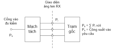
Figure A. 1 – Receiver test setup
For spurious emissions from the receiver antenna connector, separate testing can be performed for each receiver antenna connector.
A.5.2. Test the generator
For each test, the test signals applied to the transmitter antenna terminals (P i) shall be large enough so that the sum of the powers of the injected signals is equal to the power of the signal(s). test (P s) is indicated in the test. This can be assessed by measuring the signals radiated by each antenna connector separately and adding the results, or by combining the signals and making a single measurement. The characteristics (e.g., amplitude and phase) of the combined network must be so large that the power of the combined signal is maximized.
An example of a suitable test configuration is shown in Figure A. 2.
![]()
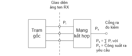
Figure A. 2 – Generator test setup
For intermodulation loss, separate testing can be performed for each transmitter antenna connector.
A.6. Transmit with multiple transmitter antenna connectors
For the tests in section 3, the requirements apply to each transmitter antenna connector in the case of transmission to multiple transmitter antenna connectors, unless otherwise specified.
The transmitter requirements are tested at the antenna connector, with the remaining antenna connector(s) terminated. If the manufacturer declares the transmitter equivalent, it is capable of measuring the signal at any transmitter antenna connector.
A.7. BS with integrated BS Iuant modem
For the tests in this specification, the integrated BS Iuant modem will be disabled. Spurious emissions as specified in 3.3.3 and 3.3.6 are measured only at frequencies greater than 20 MHz with the integrated BS Iuant modem enabled, unless otherwise specified.
![]() Appendix B
Appendix B
(Reference)
Environmental conditions
This section defines the environmental conditions for each BS test.
The following environmental conditions are due supplier declares:
- Atmospheric pressure: lowest and highest;
- Temperature: lowest and highest;
- Relative humidity: lowest and highest;
- Power supply: upper and lower voltage limits.
When operating outside the boundary limits of the declared operating environmental conditions, this device must not affect the efficient use of the spectrum and cause harmful interference.
PHỤ LỤC B
B.1. Normal testing environment
When a normal test environment is specified, testing shall be performed within the lowest and highest limits of the conditions specified in Table B.1.
Table B. 1 – Limiting conditions for the test environment
|
Condition |
Lowest |
Highest |
|
Atmospheric pressure |
86 kPa |
106 kPa |
|
Temperature |
15 °C |
30 °C |
|
Relative humidity |
20 % |
85 % |
|
Power source |
Designation, declared by the manufacturer |
|
|
Vibration |
Trivial |
|
The above ranges of atmospheric pressure, temperature and humidity correspond to the maximum variation expected in the uncontrolled environment of a test laboratory. If it is not possible to maintain these parameters within the specified limits, the actual values shall be recorded in the test report.
NOTE: For example, radiated emission measurements in an extended field test site.
B.2. Critical test environment
The manufacturer must declare one of the following conditions :
1) The device type represents the device to be tested, as defined in TCVN 7921 -3-3.
2) The device type represents the device to be tested, as defined in TCVN 7921 -3-4.
3) For equipment not complying with the classes mentioned, the relevant classes in TCVN 7921 for temperature, humidity and vibration, must be declared.
NOTE: Performance degradation due to environmental conditions outside standard operating conditions is not measured in this specification. These environmental conditions can be specified and measured separately.
B.2.1. Critical temperature
When a critical temperature test environment is specified for a test, the test shall be performed with the manufacturer's declared standard minimum and maximum operating temperatures. for the equipment to be tested.
Lowest temperature:
Testing must be performed with equipment and environmental measurement methods including environmental phenomena required to impact the equipment, following the test procedures of TCVN 7699-2-1.
Highest temperature:
Testing must be performed with equipment and environmental measurement methods including environmental phenomena required to impact the equipment, following the test procedures of TCVN 7699-2-2.
NOTE: It is recommended that the equipment be fully functional before being brought to its lower operating temperature.
B.3. Vibration
When vibration conditions are specified for a test, the test shall be performed with the equipment vibrated in a sequence determined by the manufacturer's declaration for the test equipment. Testing must use environmental measurement equipment and methods, including environmental phenomena required to impact the equipment, following the measurement procedures of TCVN 7699-2-6. Other environmental conditions shall be within the range specified in B.1.
NOTE: Higher vibration levels may cause excessive physical stress within the equipment after a prolonged test. The test team should only vibrate the device during RF measurements.
B.4. Supply
When extreme power supply conditions are specified for a test, the test shall be performed with the upper and lower reference limits of the operating voltage determined by the manufacturer's declaration for the equipment being tested.
Upper voltage limit:
The device must be supplied with a voltage equal to the upper limit as declared by the device manufacturer (as measured at the device inputs). Tests must be performed with the lowest and highest steady-state temperature limits as declared by the manufacturer for the device, with the methods specified in TCVN 7699-2-1: Ab Test /Ad and TCVN 7699-2-2: Bb/Bd measurement: Dry heating.
Lower voltage limit:
The device must be supplied with a voltage equal to the lower limit as declared by the device manufacturer (as measured at the device inputs). Tests must be performed with the lowest and highest steady-state temperature limits as declared by the manufacturer for the device, with the methods specified in TCVN 7699-2-1: Ab Test /Ad and TCVN 7699-2-2: Bb/Bd measurement: Dry heating.
B.5. Measurements for test environments
The measurement accuracy of the BS test environment defined in Annex B is:
Pressure: ±5 kPa.
Temperature: ±2 degrees.
Relative humidity: ±5%.
DC voltage: ±1.0%.
AC voltage: ±1.5 % .
Vibration: ±10%.
Vibration frequency: 0.1 Hz.
The above values shall be applied, unless the test environment is controlled and the specifications for controlling the test environment specify uncertainties for the parameters.
 Appendix C
(Reference)
Measurement diagram
PHỤ LỤC C
C.1. Transmitter
C.1.1. Output power, dynamic output power, transmit signal quality, frequency error, EVM, DL RS power, unwanted emissions
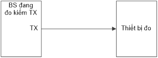
Figure C. 1 – System setup for measuring base station output power, dynamic output power , transmitted signal quality, frequency error, EVM, DL RS power, unwanted emissions
C.1.2. Cross-modulation of the transmitter
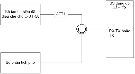
Figure C. 2 – Transmitter intermodulation measurement system setup
C.1.3. Time calibration error
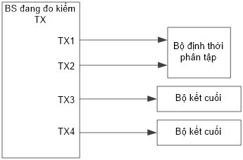
Figure C. 3 – Setting up the time correction error measurement system
C.1.4. Indoor BS output power to protect neighboring channels
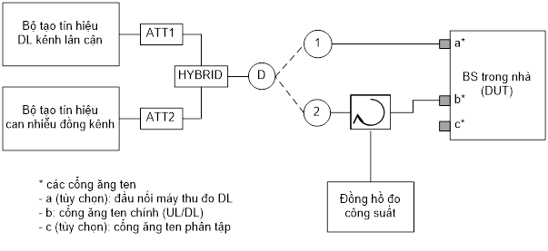
Figure C. 4 – Set up an indoor BS output power measurement system to protect neighboring channels
C.1.5. Indoor BS output power for E-UTRA co-channel protection
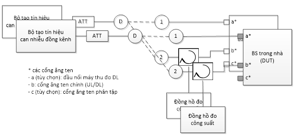
Figure C. 5 – (Option 1) Set up an indoor BS output power measurement system for E-UTRA co-channel protection
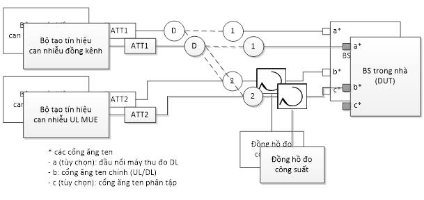
Figure C. 6 – (Option 2) Set up an indoor BS output power measurement system for E-UTRA co-channel protection
C.2. Receiver
C.2.1. Standard selectivity level
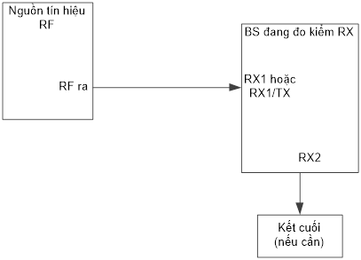
Figure C. 7 – Setting up a base station standard selective level measurement system
C.2.2. Dynamic range
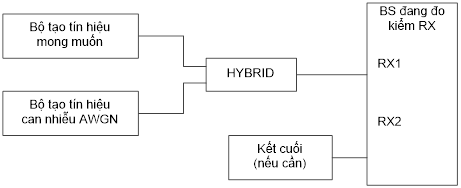
Figure C. 8 – Set up the dynamic range measurement system
C.2.3. Selective in channels
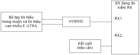
Figure C. 9 – In-channel selectivity measurement system setup
C.2.4. Selective adjacent channel (ACS) and narrowband blocking
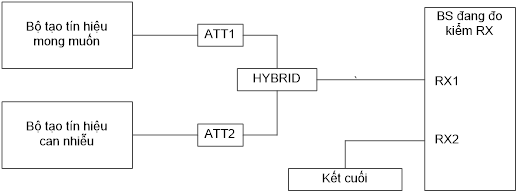
Figure C. 10 – Narrowband blocking and adjacent channel selectivity measurement system setup
C.2.5. Blocking properties
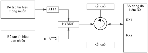
Figure C. 11 – System setup for measuring blocking characteristics
C.2.6. Receiver spurious emissions
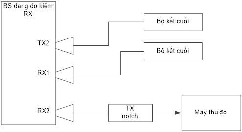
Figure C. 12 – Receiver spurious emission measurement system setup
C.2.7. Intermodulation characteristics
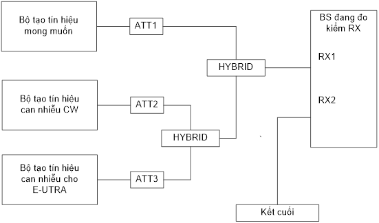
Figure C. 13 – System setup for measuring intermodulation characteristics
Appendix D
(Regulations)
HS code of E-UTRA mobile communication base station equipment
|
TT |
Name of products and goods according to QCVN |
HS code |
Description of products and goods |
|
01 |
E-UTRA mobile communication base station equipment |
8517.61.00 |
Base station equipment in mobile phone networks using E-UTRA FDD or TDD technology with or without integrating one or more of the following functions: - GSM mobile communication base station equipment; - W-CDMA FDD mobile communication base station equipment; - Fifth generation (5G) mobile communication base station equipment. |
References
[1] ETSI EN 301 908-1 V1 5 .1.1 (20 21 -0 9 ) : "IMT cellular networks; Harmonized Standard covering the essential requirements of article 3.2 of the Directive 2014/53/EU; Part 1: Introduction and common requirements".
[2] ETSI EN 301 908-14 V1 5 . 1.1 (20 21 -0 9 ) : IMT cellular networks; Harmonized Standard covers the essential requirements of article 3.2 of the Directive 2014/53/EU; Part 1: Introduction and common requirements.
You are not logged in.
This feature is available to Advanced account holders. Please log in to access detailed information on Related documents.
If you do not have an account, please register here!
VIETNAMESE DOCUMENTS
This utility is available to subscribers only. Please log in to a subscriber account to download. Don’t have an account? Register here
This utility is available to subscribers only. Please log in to a subscriber account to download. Don’t have an account? Register here
ENGLISH DOCUMENTS
This utility is available to subscribers only. Please log in to a subscriber account to download. Don’t have an account? Register here

