Decision 2747/QD-BYT 2025 on guidelines for establishing medical oxygen systems for medical examination and treatment facilities
- Summary
- Content
- Status
- Vietnamese
- Related documents
- Diagram
- Download
Please log in to your Advanced Package to view the full text. Do not have an account yet? Register here.
Please log in to use this function
Please log in to use this function
ATTRIBUTE
| Issuing body: | Ministry of Health | Effective date: |
Known
Please log in to a subscriber account to use this function. Don’t have an account? Register here |
| Official number: | 2747/QD-BYT | Signer: | Tran Van Thuan |
| Type: | Decision | Expiry date: | Updating |
| Issuing date: | 27/08/2025 | Effect status: |
Known
Please log in to a subscriber account to use this function. Don’t have an account? Register here |
| Fields: | Health |
The Effect status of this document is known.This feature is available to Advanced account holders. Please log in to a subscriber account to view Effect status. Don’t have an account? Register here
|
THE MINISTRY OF HEALTH |
THE SOCIALIST REPUBLIC OF VIETNAM |
DECISION
On promulgation of the “Guidelines for establishing medical oxygen systems for medical examination and treatment facilities”
__________________
THE MINISTER OF HEALTH
Pursuant to the Law No. 15/2023/QH15 dated January 09, 2023 on Medical Examination and Treatment;
Pursuant to Decree No. 42/2025/ND-CP dated February 27, 2025 of the Government defining the functions, tasks, powers and organizational structure of the Ministry of Health;
Based on the need to enhance medical oxygen supply capacity at medical examination and treatment facilities, especially in the context of epidemic prevention and control and medical emergencies;
At the request of the Director of the Infrastructure and Medical Device Administration;
DECIDES:
Article 1. To promulgate under this Decision the “Guidelines for establishing medical oxygen systems for medical examination and treatment facilities”.
Article 2. These guidelines apply to public and non-public medical examination and treatment facilities nationwide to:
a) Ensure the medical oxygen supply system is designed, installed, managed, operated, and maintained safely, continuously, and effectively, serving medical examination and treatment activities;
b) Serve as a basis to build a new, upgrade, or renovate the medical oxygen infrastructure system corresponding to the scale, nature, functions, and tasks of each medical facility as decided by the competent authorities.
Article 3. This Decision takes effect from the date of its signing for promulgation.
Article 4. The Chief of the Ministry Office, the Director of the Infrastructure and Medical Device Administration, the Director of the Agency of Medical Services Administration, the Directors and General Directors of Departments and Agencies under the Ministry of Health, the Directors of hospitals and institutes with patient beds under the Ministry of Health, the Directors of provincial-level Departments of Health of provinces and municipalities, and the Heads of health agencies of Ministries and Sectors shall be responsible for the implementation of this Decision./.
|
|
FOR THE MINISTER |
THE MINISTRY OF HEALTH
THE INFRASTRUCTURE & MEDICAL DEVICE ADMINISTRATION, THE AGENCY OF MEDICAL SERVICES ADMINISTRATION
GUIDELINES FOR ESTABLISHING MEDICAL OXYGEN SYSTEMS FOR MEDICAL EXAMINATION AND TREATMENT FACILITIES
2025
THE SOCIALIST REPUBLIC OF VIETNAM
Independence - Freedom - Happiness
____________________
GUIDELINES FOR ESTABLISHING MEDICAL OXYGEN SYSTEMS FOR MEDICAL EXAMINATION AND TREATMENT FACILITIES
(Promulgated under Decision No. 2747/QD-BYT dated August 27, 2025)
|
|
Drafting agency: The Infrastructure and Medical Device Administration. Co-drafting: The Agency of Medical Services Administration, PATH |
2025
DRAFTING COMMITTEE FOR
GUIDELINES FOR ESTABLISHING MEDICAL OXYGEN SYSTEMS FOR MEDICAL EXAMINATION AND TREATMENT FACILITIES
|
Directed the drafting |
|
|
Assoc. Prof., Ph.D. Tran Van Thuan |
Deputy Minister of Health |
|
Ph.D. Nguyen Minh Loi |
Director of the Infrastructure and Medical Device Administration. |
|
Editor in chief |
|
|
Ph.D. Nguyen Trong Khoa |
Deputy Director of the Agency of Medical Services Administration |
|
Co-Editors in chief |
|
|
M.A. Nguyen Anh Tu |
Deputy Director of the Infrastructure and Medical Device Administration. |
|
Ph.D. Vuong Anh Duong |
Deputy Director of the Agency of Medical Services Administration |
|
Drafting members |
Members of the Drafting Committee under Decision No. 992/QD-BYT dated April 16, 2024 of the Ministry of Health. |
|
Secretariat |
|
|
M.A. Truong Le Van Ngoc |
Head of the Division for Professional Operations and Health Protection - the Agency of Medical Services Administration |
|
M.A. Nguyen Thanh Toan |
Infrastructure and Medical Device Administration |
|
M.A. Vu Tien Son |
The Infrastructure and Medical Device Administration |
|
Med. Dr. Nguyen Thi Dung |
The Rehabilitation and Assessment Division - the Agency of Medical Services Administration |
|
Med. Dr. Do Thi Ngat |
The Division for Professional Operations and Health Protection - the Agency of Medical Services Administration |
|
Bachelor Do Thi Thu |
The Agency of Medical Services Administration |
|
Technical support |
|
|
Ph.D. Nguyen To Nhu |
Director of PATH's Global Health Security Program |
|
M.A. Nguyen Phu Cuong |
PATH personnel |
|
M.A. Nguyen Le Linh Chi |
PATH personnel |
PREFACE
The guidelines for establishing medical oxygen systems are developed to support medical examination and treatment facilities in the process of designing, implementing, and operating medical oxygen supply systems safely and effectively. These guidelines are based on international standards as well as applicable law regulations in Vietnam.
These guidelines provide methods for determining specific oxygen demand for each medical examination and treatment facility, while unifying guidelines on applying relevant regulations, calculating design conditions, installation, commissioning, and putting the system into operation.
In pursuance to these guidelines, medical facilities can invest in medical oxygen systems with appropriate capacity, optimize costs, ensure synchronization, and be ready for future development and expansion.
LIST OF ABBREVIATIONS
|
QCVN: |
Vietnam Technical Regulation |
|
TCVN: |
Vietnam Technical Standard |
|
ISO: |
International Organization for Standardization |
|
HTM: |
Health Technical Memorandum (United Kingdom) |
|
NFPA: |
National Fire Protection Association (United States) |
|
DIN: |
Deutsches Institut für Normung (German Institute for Standardization) - Commonly used to refer to the DIN gas outlet standard |
|
BS, Ohmeda: |
Types of medical gas connector standards |
|
AVSU: |
Area Valve Service Unit |
|
PSA/DSA: |
Pressure Swing Adsorption - On-site oxygen generation technology |
|
LOX: |
Liquid Oxygen |
|
SCADA: |
Supervisory Control and Data Acquisition |
|
BMS: |
Building Management System |
|
ICU: |
Intensive Care Unit |
|
NICU: |
Neonatal Intensive Care Unit |
|
LV: |
Low Voltage |
|
ELV: |
Extra-Low Voltage |
|
PPE: |
Personal Protective Equipment |
TABLE OF CONTENTS
CHAPTER I: GENERAL PROVISIONS
1.1. Scope of application
1.2. References and citations
1.3. Terms and definitions
CHAPTER II: COMPONENTS OF THE MEDICAL OXYGEN SYSTEM
2.1. Oxygen storage equipment (Oxygen supply source)
2.2. Central pressure regulating station
2.3. Gas pipeline system
2.4. Area Valve Service Unit
2.5. Gas outlet
2.6. Alarm and monitoring system
2.7. Terminal devices
CHAPTER III: STEPS TO ESTABLISH A MEDICAL OXYGEN SYSTEM
3.1. General requirements
3.2. Oxygen demand calculation
3.3. Oxygen system establishment
3.3.1. Oxygen supply source:
3.3.2. Distribution network
3.3.3. Peripheral devices
3.3.4. Electrical requirements
3.3.5. Earthing
3.3.6. Regulations on alarm signals
CHAPTER IV: SYSTEM INSTALLATION AND MAINTENANCE
4.1. Installation
4.2. System maintenance
4.3. Documentation of operation records and maintenance logs
4.4. Technical safety inspection of the medical oxygen system
4.5. Specific risks when using liquid oxygen systems
CHAPTER V: EMERGENCY RESPONSE
5.1. Common emergencies
5.2. Emergency response
APPENDIX
CHAPTER I: GENERAL PROVISIONS
1.1. Scope of application
These guidelines are developed to guide medical examination and treatment facilities at all technical professional levels within the Vietnam healthcare system, from highly specialized levels to primary healthcare levels, in establishing and operating medical oxygen supply systems safely, effectively, and ensuring full compliance with the law regulations.
The guidelines include:
- Planning the design, new construction, or renovation of medical oxygen supply systems at the facility, and deploying the installation of central medical gas systems or independent oxygen supply systems.
- Technical, safety, and effectiveness requirements during the operation and use of medical oxygen.
- Technical standards and professional guidelines related to medical oxygen systems.
Target users:
- State regulatory authorities.
- Medical examination and treatment facilities that demand medical oxygen.
- Consultants for the design and construction of medical gas systems.
1.2. References and citations
The design, installation, and operation of medical oxygen systems must comply with the following technical regulations and standards:
1.2.1. Domestic
- Law on Medical Examination and Treatment (amended) as well as decrees and circulars guiding the Law on Medical Examination and Treatment.
- TCVN 7742:2007 - Oxygen concentrator supply systems for use with medical gas pipeline systems.
- TCVN 8022-1:2009 - Pipeline systems for compressed medical gases and vacuum.
- TCVN 4470:2012 - General hospital - Design standard.
1.2.2. International
- ISO 7396-1:2021 - Medical gas pipeline systems: Design and installation;
- Design standard: HTM 02-01 (UK) - Medical gases - Health Technical Memorandum (United Kingdom);
- NFPA 99, Health Care Facilities Code for the design, installation, and testing; operation and maintenance management of medical gas systems: ISO 7396-1 (Medical gas pipeline systems - Part 1: Pipeline systems for compressed medical gases and vacuum) and ISO 7396-2 (Medical gas pipeline systems - Part 2: Anaesthetic gas scavenging disposal systems);
- Air Liquide Medical Systems (Medical Gas Design Guide);
- EN ISO 9001, EN ISO 13485, EN 13348, EN 1057, FSC.
1.3. Terms and definitions
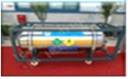
Liquid oxygen vessel (also known as a liquid oxygen storage vessel) means specialized equipment used to store oxygen in liquid form under high pressure and low temperature. Oxygen vessels are commonly used in medical facilities such as hospitals, clinics, etc. to provide a continuous and stable supply of medical oxygen for patients.
|
Figure 1.1. Liquid oxygen vessel |
|
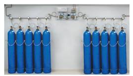
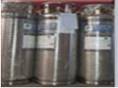
Manifold (gas cylinder manifold) means a group of gas cylinders with equivalent capacity connected together through pipelines, valves, and pressure regulators (opening/closing automatically or manually), aimed at collecting gas from multiple cylinders to supply oxygen for use or standby purposes. In large medical facilities, this manifold is often used as a standby supply system.
|
|
Figure 1.2. Manifold (Oxygen cylinder manifold) |
|
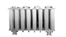
Vaporizer: A device that converts oxygen from a liquid state to a gaseous state for use. Liquid oxygen is stored in vessels at extremely low temperatures, and when needed for use, it is vaporized into gaseous oxygen through a temperature-increasing process.
|
|
Figure 1.3. Vaporizer |
|
PSA oxygen generator: A system that concentrates oxygen from ambient air using pressure swing adsorption technology, producing oxygen with a concentration of 93±3%.
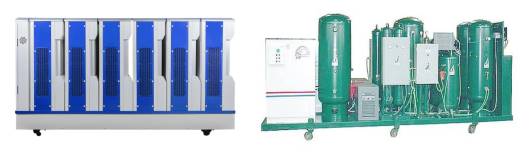
Figure 1.4. PSA oxygen generator
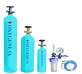
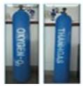
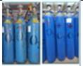
Oxygen cylinder: A specialized type of container used to store and supply oxygen in a gaseous state. Oxygen cylinders are made of high-pressure-resistant materials such as steel or aluminum alloys, capable of withstanding great pressure to ensure safety during use.
|
|
Figure 1.5. Oxygen cylinders |
|
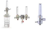
Peripheral devices: Additional equipment or components used outside the medical oxygen supply system to support the supply, control, monitoring, or direct use of medical oxygen for patients effectively, safely, and meeting usage demands.
|
|
Figure 1.6. Peripheral devices |
|
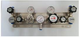
Valve control system: A collection of valves and equipment that control the flow and pressure of oxygen in an oxygen supply system. This system ensures that oxygen is supplied at the correct pressure and safely to usage areas such as emergency rooms, ICUs, operating rooms, and other areas in a hospital or medical facility.
|
|
Figure 1.7. Valve control system |
|
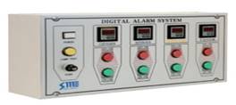
Alarm system: A collection of devices and sensors designed to monitor and alert the medical oxygen supply system. When a fault or abnormality occurs, such as a pressure drop, pressure increase, leak, or oxygen shortage, the alarm system will activate audio and visual warning signals or send notifications to medical staff for prompt handling.
|
|
Figure 1.8. Alarm system |
|
CHAPTER II: COMPONENTS OF THE MEDICAL OXYGEN SYSTEM
A central medical oxygen system consists of multiple interconnected components, designed, installed, and operated in a continuous process. The goal is to ensure a stable, safe supply of oxygen and promptly meet the treatment needs at a medical facility. Below are the main components of the system:
2.1. Oxygen supply source
There are three common types of oxygen supply sources:
- Liquid oxygen (LOX) vessel: Large capacity, containing oxygen in liquid form to be vaporized to supply the system. Typically used in medical facilities with a large number of hospital beds.
- Oxygen cylinder manifold: Consists of multiple gaseous oxygen cylinders compressed at high pressure (140-150 bar), the commonly used capacity is the 40-liter cylinder type, connected via a system of valves and pressure regulators.
- PSA oxygen generator: Separates oxygen from the air via pressure swing adsorption technology. Often used in remote, isolated areas or places difficult to access commercial oxygen sources, ensuring the requirements in section 3.3.1.3.
Requirements:
- The source of oxygen supplied to the system must be stable, maintaining a pressure suitable for the system design;
- The purity of oxygen must meet applicable pharmacopoeia standards, for industrially produced oxygen: ≥ 99.5% for liquefied oxygen and compressed oxygen (according to the Vietnamese Pharmacopoeia, USP, BP, Ph. Eur.) or ≥ 93% ± 3% for oxygen generated from a PSA plant, the system is designed, installed, and operated in accordance with standards (ISO 7396-1, HTM 02-01, NFPA 99, etc.);
- Additionally, medical oxygen must not contain harmful impurities such as CO, CO2, oil, or microorganisms.
2.2. Central pressure regulating station
This is where the oxygen pressure is adjusted from the supply source down to a level suitable for the system (usually from 3.5 to 5 bar). Main components include:
- Primary and secondary pressure regulating valves.
- Source switching valves (automatic or semi-automatic).
- Gas filters and safety valves.
Function: Ensures stable pressure throughout the system and protect oxygen-using equipment from overpressure phenomena.
2.3. Gas pipeline system
- A network of pipes (usually made of copper), conducting oxygen from the pressure regulating station to usage areas such as patient rooms, ICUs, and operating rooms.
- Should be installed logically, limiting sharp bends to prevent gas leaks.
- Must use medical-grade standard pipes and test the pressure before putting into operation.
Note: It is recommended to zone the pipeline according to the usage area (ICU, operating room, etc.) for easy control and maintenance.
2.4. Area Valve Service Unit (AVSU)
- Function: Helps shut off gas to individual areas when maintenance is needed or when a fault occurs, without disrupting the entire system.
- Structure: Includes a lock valve, a pressure gauge, protective glass against unauthorized opening, and an area name display panel.
- Siting: Usually placed in the corridor, near usage areas such as intensive care units (ICU), neonatal intensive care units (NICU), operating rooms, or inpatient accommodation units, etc.
2.5. Gas outlet
- The place where oxygen is supplied directly at the hospital bed or treatment point.
- Must use internationally standard outlets (DIN, BS, Ohmeda).
- Devices such as flowmeters, ventilators, or humidifiers can be attached here.
2.6. Alarm and monitoring system
- Includes devices to monitor pressure, flow, and detect faults such as leaks, loss of oxygen source, and abnormal pressure.
- Siting: At the Technical Center and at each Area Valve Service Unit (AVSU).
- Advanced options: Can be integrated into a central monitoring system such as a Supervisory Control and Data Acquisition (SCADA) system or Building Management System (BMS) for more effective management.
2.7. Terminal devices
These are medical devices that use oxygen directly at the treatment area, including:
- Flowmeter: Used to adjust the amount of oxygen supplied to the patient.
- Humidifier: Humidifies the oxygen to prevent drying out the respiratory mucosa.
- Ventilators, non-invasive respiratory support devices, etc. Connected to the oxygen outlet or standby oxygen cylinder to support treatment.
Requirements: These devices should be periodically inspected, calibrated, and cleaned according to proper procedures to ensure patient safety.
CHAPTER III: STEPS TO ESTABLISH A MEDICAL OXYGEN SYSTEM
3.1. General requirements
Oxygen supply source
The medical oxygen system must be connected to a central source of supply, ensuring continuity, stability, and reliability. The supply source must be operated and maintained according to applicable regulations. When designing a medical oxygen supply system in a medical facility, there must be a primary supply and at least one standby system. This standby system can be one of the following types or a combination thereof:
- Gaseous oxygen in individual cylinders or a high-pressure cylinder manifold;
- Liquid oxygen stored in vessels or large cylinders;
- Oxygen generator (PSA/DSA).
The oxygen source must be completely separate from other medical gas systems. All parts of the system should be clearly marked, and specialized connectors and outlets shall be used for each type of gas to prevent incorrect connections or confusion between systems and devices.
Distribution pipeline system
The pipeline system must be designed and installed securely, absolutely leak-proof, ensuring gas is conducted from the central source to usage points safely and effectively. The pipeline network must be marked with color bands and arrows indicating the direction of gas flow. The pipeline must not be designed to run hidden inside walls. A wall penetration must have an outer sleeve pipe so that the outer surface of the gas pipeline does not come into direct contact with plaster or mortar. A wall penetration must have a gap to avoid the gas pipeline breaking or cracking due to the expansion and contraction of the construction works.
Terminal units
The terminal is where oxygen is directly supplied to patients or medical equipment. These outlets should be installed to standards and arranged logically, thereby minimizing the risk of misconnection, and ensuring convenience during use.
Monitoring and alarm system
Continuous monitoring of the entire system is a mandatory element, to promptly detect and handle abnormal situations. The system should include the following functions:
- Pressure alarm: Alerts when the gas pressure increases or decreases beyond the allowable threshold, helping to early detect the risk of leaks or supply source malfunctions.
- Emergency alarm: Activates when the pressure deviates beyond the safe limit, posing an immediate danger to patients.
- Operational alarm: Alerts minor faults that should be monitored, maintained, or repaired promptly to avoid serious incidents.
Emergency response procedure
It is necessary to develop and disseminate an emergency response procedure to cope with source loss incidents, gas leaks, or interruptions in the oxygen supply, ensuring absolute safety during the use and operation of the system.
3.2. Oxygen demand calculation
3.2.1. Demand forecasting
To calculate oxygen demand accurately, the following basic factors must be considered:
- Determination of the number of oxygen-using terminal units: Calculate the points needing oxygen such as hospital beds, ICU rooms, emergency rooms, and other treatment areas.
- Forecasting of the maximum number of patients: Determine the number of patients who may use oxygen in normal situations as well as in emergencies such as resuscitation, surgery, and severe disease cases.
- Calculation of maximum oxygen demand: Forecast the total amount of oxygen needed in emergencies when multiple patients need oxygen simultaneously.
- Consideration of expansion or upgrade plans: Evaluate the future development capability of the medical facility to have a plan for adjusting the oxygen demand accordingly.
- Hospital type: Clearly determine the hospital type (general, specialized, hospital class), because each type will have a different oxygen demand.
- Simultaneous usage factor: Evaluate the simultaneous oxygen usage rate of the units at the time of maximum usage. This helps determine the oxygen consumption level when the entire system operates at full capacity.
- Evaluation of necessary medical equipment: Includes the number of hospital beds, operating rooms, ICU rooms, emergency rooms, and other areas with oxygen demand.
- Evaluation of the distance between the facility and the oxygen supplier: Calculate the distance to determine the travel time of oxygen refill suppliers to calculate the vessel or cylinder capacity necessary for the system.
3.2.1. Quick reference table for oxygen demand of facilities
Table 3.1. Oxygen usage demand of medical examination and treatment facilities/hospital beds by hospital class.
Unit: Liters of gas/minute/bed
|
No. |
Medical examination and treatment facility scale (beds) |
Usage demand |
|||
|
Special class hospitals |
Class I hospitals |
Class II hospitals |
Class III hospitals |
||
|
1 |
Hospitals with less than 50 beds |
|
0.2 liters/minute/bed |
0.2 liters/minute/bed |
0.1 liters/minute/bed |
|
2 |
Hospitals from 50-250 beds |
||||
|
3 |
Hospitals from 250-500 beds |
0.7 liters/minute/bed |
0.4 liters/minute/bed |
0.4 liters/minute/bed |
0.3 liters/minute/bed |
|
4 |
Hospitals with more than 500 beds |
0.9 liters/minute/bed |
0.5 liters/minute/bed |
0.5 liters/minute/bed |
0.4 liters/minute/bed |
The capacity of the oxygen vessel or cylinder is calculated using the following formula:
B = L × G × K × N × Q
Where:
- B: Oxygen vessel capacity, in cases of calculating the volume of a liquid oxygen vessel - use the conversion ratio of 885.78 from liters in gaseous form to 01 liter in liquid form.
- L: Used oxygen flow rate (referenced from the table based on the oxygen usage demand of each medical facility).
- G: Number of patient beds of the medical facility.
- K: Applied coefficient (For specialized surgical and trauma medical facilities, emergency centers, medical facilities with high oxygen usage demand, medical facilities with supply sources far from the production site, the usage flow rate is calculated with a coefficient from 1.2 to 1.5).
- N: Number of days before oxygen must be refilled.
- Q: Flow rate conversion from minutes to days (Q = 1440, because there are 1440 minutes in a day).
Specifications of some common transportable liquid oxygen vessels and gas cylinders, conversion formula: 01 ton of liquid oxygen = 777 m3 of gaseous oxygen at 30ºC.
Table 3.2. Specifications of some common transportable liquid oxygen vessels and gas cylinders
|
No. |
Type |
Liquid oxygen capacity |
Liquid oxygen mass (kg) |
Converted gas volume (m3)/number of 40L-150bar cylinders |
Illustrative image |
|
1 |
Transportable liquid oxygen vessel |
1m3/1000 liters |
1,140 kg |
885.78 m3/148 oxygen cylinders (40 liters, 150 bar pressure) |
|
|
2 |
Transportable liquid oxygen vessel |
0.5m3/500 liters |
570 kg |
442.89 m3/74 oxygen cylinders (40 liters, 150 bar pressure) |
|
|
3 |
Transportable liquid oxygen cylinder |
0.175m3/175 liters |
199 kg |
155 m3/26 oxygen cylinders (40 liters, 150 bar pressure) |
|
|
4 |
Gaseous oxygen cylinder |
40 liters |
|
6 m3 of gas at 150 bar pressure |
|
|
5 |
Gaseous oxygen cylinder |
8-10 liters |
|
1.2 m3 - 1.5 m3 of gas at 150 bar pressure |
|

3.3. Oxygen system establishment
The oxygen supply system consists of the following main components:
- Oxygen (liquid oxygen, gaseous oxygen, or oxygen generator) supply/standby supply;
- Pipeline system;
- Peripheral devices.
3.3.1. Oxygen supply source:
The design of the medical oxygen supply source must meet strict requirements to ensure the system operates effectively, safely, and fully meets usage demands. The selection of the supply source type is based on the scale, actual demand, and supply conditions of each medical facility. Types of supply sources typically include:
- Liquid oxygen vessel
- Oxygen cylinder
- PSA oxygen generator
The oxygen source must include at least 2 supply sources: primary and standby. The capacity of the supply sources and their locations will depend on the system's design parameters and the specific needs of the medical facility.
- For large-scale facilities: Using liquid oxygen is encouraged due to its ability to supply large capacities, cost savings, and convenience in management.
- For small-scale or specialized facilities: Oxygen cylinders or PSA oxygen generators can be used. Oxygen cylinders should be manifolded and connected near the usage area, ensuring convenience during replacement.
- The PSA oxygen generator is suitable for medical facilities in remote, isolated areas or areas where it is difficult to access medical oxygen supply from outside. When using PSA, it is mandatory to fully comply with technical requirements, continuously monitor oxygen quality as stated in section 3.3.1.3, and only use it for patients as prescribed by a doctor.
From the supply source to the pipeline system and the terminal gas units, everything must be clearly identified and marked to avoid confusion with other gas systems. The area housing the oxygen supply source should be security protected, have warning signs, ventilation, and safety measures according to standards.
3.3.1.1. Source of supply by Liquid oxygen vessel and vaporizer (LOX system):
The liquid oxygen supply system consists of the following main components:
- Liquid oxygen storage vessel:
+ A device that stores oxygen in a liquid state.
+ The vessel must be designed with a minimum pressure of 17 bar to ensure safety and suitability for the supply system.
- Pressure Build-Up Unit:
+ Responsible for maintaining stable pressure in the storage vessel to ensure liquid oxygen can be vaporized and distributed evenly within the system.
- Vaporizer:
+ A device that converts oxygen from a liquid state to a gaseous state at ambient temperature.
+ This vaporization process allows oxygen to be used in the medical gas distribution system.
- Control and monitoring panel:
+ Consists of devices to measure oxygen capacity and pressure, and supports remote monitoring to track the operating status of the vessel and the system.
a. Requirements of the LOX system
The liquid oxygen storage vessel is a low-temperature liquefied oxygen container, made of materials suitable for medical gases, usually stainless steel, and installed on a fixed pedestal or frame, meeting safety requirements regarding mechanical, thermal, and fire prevention and fighting aspects. The vessel has a double-shell structure: the inner vessel contains liquid oxygen, the outer jacket bears the load and provides protection; the space between the two shells is vacuumed and/or stuffed with specialized insulating materials to limit heat transfer, maintaining oxygen in a liquid state.
The vessel capacity must be designed based on actual consumption demand, supply capability, and safe operation requirements, ensuring continuous and stable oxygen supply, reducing refilling frequency, and limiting interruption risks.
The system must be equipped with an emergency reserve supply (which can be a bank of compressed cylinders or a small vessel) capable of supplying oxygen to the facility for a minimum duration as prescribed by the applicable standards, aimed at maintaining safe operations when the primary supply source is temporarily suspended. The standby supply can be:
- Compressed gas cylinder manifolds connected and gathered into a system.
- A secondary liquid oxygen storage vessel, used exclusively for standby purposes.
![]()
![]()
![]()
![]()
Figure 3.1. Illustrative LOX system layout with cylinder backup
Figure 3.2. Illustrative LOX system layout with storage vessel standby
The pressure in the liquid oxygen system (LOX) is controlled automatically via a pressure regulator. This regulator controls the flow of liquid oxygen entering the pressure build-up vaporizer to maintain stable pressure throughout the system.
After vaporization, the gaseous oxygen is introduced into the system with a minimum pressure of 10.5 bar, ensuring it meets operational requirements and provides a continuous gas supply for medical equipment.
In cases where multiple vaporizers are installed, a system for automatic switching between vaporizers should be arranged to:
- Distribute the load evenly,
- Prevent local overload situations,
- Increase system reliability and lifespan.
The capacity of the vaporizer must be carefully calculated based on the highest simultaneous oxygen consumption peak at the facility. This is to ensure the system always has sufficient capacity to supply gas, even when demand peaks.
b. Direct capacity measurement and remote monitoring system:
The liquid oxygen (LOX) storage vessel must be equipped with a capacity gauge displaying the amount of liquid oxygen currently in the vessel. These gauges must be accurately calibrated to ensure reliability and are provided and calibrated by the gas supplier.
A remote monitoring system should be installed, capable of:
- Continuously tracking the capacity level and pressure of the storage vessel.
- Recording operational data in real-time.
- Early detecting potential issues so the system always operates stably.
Monitoring data is used to:
- Track oxygen consumption over time.
- Determine current storage levels and the ability to maintain supply.
- Plan system maintenance while forecasting future oxygen consumption demand.
For LOX systems directly operated by the oxygen supplier, the supplier will proactively:
- Design, install, operate, and maintain the system,
- Adjust accordingly based on the actual usage needs of the medical facility.
The central control panel of the LOX system is designed to:
- Accept a supply of gaseous oxygen from the primary storage vessel at 10.5 bar minimum.
- In cases where a standby supply (manifold) is used, the output pressure reaches a minimum of 4.2 bar.
- Subsequently, the gas is depressurized down to 4.2 bar before being distributed into the pipeline system leading to the usage areas within the facility.
c. Sites for the LOX system
The LOX system, including the vessel, control panel, and standby manifold, must be located inside a fenced compound. This location may also be reserved for the storage of other non-flammable cryogenic gases. It is not recommended to install the LOX system inside an enclosed building or basement due to risks related to fire, explosion safety, and ventilation. In cases where installation inside a building is mandatory, the facility must strictly comply with applicable technical standards and safety regulations (if any), including:
- Natural or mechanical ventilation,
- Fire and explosion warning and prevention systems,
- Minimum safety distances, etc.
Space should be provided to facilitate any maneuvering of the delivery vehicle. Typical turning circle dimensions are per Table 3.3. Typical turning circle dimensions
|
|
Coupled length (m) |
Width (m) |
Turning circle (m) |
|
Articulated vehicle |
16.5 |
2.5 |
27.5 |
|
Rigid vehicle |
8.6 |
2.5 |
20.0 |
The site for the LOX system must comply with safety distances presented in Figure 3.3. The liquid oxygen vessel should be at least 8 m from roads or buildings. The plinth should be concrete. It should be clean, free from rubbish and not used as a general storage area.
Safety distances for liquid oxygen storage according to Table 3.4.
|
Size of liquid oxygen vessel |
|
||
|
Liquid oxygen vessel (tons) |
Storage vessels |
||
|
Weight capacity (tons) |
Liquid capacity (m3) at 15°C |
Distance (meters) |
|
|
|
0 - 1.1 |
0 - 2.2 |
6.0 |
|
|
1.1 - 4.0 |
2.2 - 7.8 |
7.5 |
|
|
4.0 - 60.0 |
7.8 - 117.0 |
15.0 |
|
|
60.0 - 150.0 |
117.0 - 124.0 |
22.5 |
|
|
150.0 & above |
294.0 & above |
30.0 |
|
|
LOX vessel and other liquefied flammable gases * cylinders above 50 kg total capacity |
7.5 |
|
Figure 3.3. Safety distance for a liquid oxygen vessel with a capacity <20 tons
Note: The safety distances are measured from the exposure to:
a) Any point on the storage system where in normal operation oxygen leakage or spillage can occur.
b) The outer jacket of the storage vessel.
c) Or from the vessel nozzles, whichever gives the greater distance.
Assumed maximum liquid phase pipework diameter 50mm nominal bore, for the liquid oxygen piping.
For buildings, the distance is measured to the nearest opening in the building, such as doors, windows, or ventilation openings.
3.3.1.2. Source of supply by compressed gas cylinder manifold:
An oxygen supply source using a compressed gas cylinder manifold consists of the following main components:
- Compressed oxygen cylinders: Divided into a duty bank and a standby bank.
- Connecting pipe system: Used to link the cylinders together and with the distribution system.
- Switchover unit: Automatic or semi-automatic, switches the supply source.
- Control and monitoring panel: Pressure regulator, which reduces pressure from the cylinder to the working pressure; Pressure gauge, which monitors pressure before and after regulation; Safety valve, which discharges when pressure exceeds limits.
- Consists of pressure and flow measurement devices, and a remote monitoring system to track the operating status and the remaining gas level.
The manifold should be selected and calculated based on the actual oxygen consumption demand of the medical facility, ensuring it meets requirements for safety, standby supply capability, and continuous operation. For facilities with low to medium consumption demands, a manifold system using a bank of compressed oxygen cylinders is usually a suitable technical and economic solution. In cases where the consumption demand is higher, consideration should be given to using a liquid oxygen system or a combined solution to improve supply efficiency, reduce operating costs, while increasing safety and stability in storage and distribution.
A typical manifold system is usually designed with a maximum of 20 cylinders, divided into two banks/groups (each bank consisting of a maximum of 10 cylinders) with an automatic changeover mechanism between the duty bank and the standby bank; the valve system, gauge faces, and pressure control unit must meet safety requirements and be easy to operate during cylinder replacement. Standby capacity must be determined based on actual consumption levels; typically, the total oxygen standby should ensure continuous supply for at least 05 days based on the facility's average consumption rate (including both duty and standby cylinders).
The volume of gas a cylinder can hold when fully charged at working pressure, often called the nominal capacity, is listed in Table 3.6. These figures have been converted to standard conditions (15°C, 1 bar pressure). The usable capacity is calculated after subtracting the residual pressure of about 7 bar.
Table 3.6. Capacity of medical gaseous oxygen cylinders used on manifolds (usable capacity is calculated with a residual pressure of 7 bar).
|
Cylinder type |
Nominal capacity at 137 bar (liters) |
|
** Usable capacity (liters) |
|
Oxygen J size (47 liters) |
6,440 |
|
6,130 |
The manifold system and control panel must be designed, manufactured, and certified suitable for a maximum working pressure of 230 bar (corresponding to a medical compressed gas cylinder nominally charged to 200 bar at 15°C), complying with standards for medical gas containers and accessories. The manifold headers should incorporate a renewable non-return valve to allow removal and replacement of any cylinder and to prevent the discharge of a bank of cylinders. In the event of a flexible tailpipe rupture, the header valve must be designed to ensure absolute safety for the entire system.
Pressure indication should be provided for the monitoring system to indicate pressure in each cylinder bank and in the central pipeline. These indicators must be provided online, allowing medical staff to track and manage the oxygen supply source effectively.
Figure 3.4. Schematic layout of the manifold system
3.3.1.3. Source of supply by oxygen generator (PSA):
A medical oxygen generation system utilizing pressure swing adsorption (PSA) technology is an effective, cost-saving solution, allowing on-site medical oxygen production with concentrations in the range of 90-96% v/v (Oxygen 93%), meeting common medical treatment requirements.
In cases where a medical facility requires pure oxygen ≥ 99.5% (e.g., certain intensive care unit - ICU applications, obstetrics, specialized surgeries), a standard PSA plant will not meet the requirement without an additional purification step. PSA technology is particularly suitable for medical facilities in remote, isolated areas or locations where it is difficult to access liquid oxygen or compressed gas cylinder supply sources.
For the PSA plant to operate stably, safely, and comply with medical standards, it should fully meet the following technical, safety, and installation guideline requirements:
a. Plant requirements:
The PSA plant must conform with the quality, operational, safety, and alarm standards of TCVN 7742:2007 or ISO 10083:2006 - “Oxygen concentrator supply systems for use with medical gas pipeline systems”, while complying with TCVN 8022-1 (ISO 7396-1) regarding medical gas pipeline systems.
Oxygen concentration, impurity limits, and other indicators must be continuously monitored, ensuring they remain within the prescribed range for Oxygen 93%. The system must be equipped with an oxygen analyzer that can alarms when the concentration falls out of limits, along with a standby supply (cylinder manifold or standby PSA) and an automatic changeover mechanism when the primary source fails to meet requirements.
The plant configuration consists of: compressors, receiver, dryers, molecular sieves, vacuum pumps, filters (pre-filter, fine filter, sterile filter), pressure regulators, and a control unit.
b. Siting
The siting of the PSA plant should allow for:
- Accessibility: The plant should have all-round access for maintenance purposes and allowance should be made for changing major components.
- Ventilation: It should allow for adequate flows of air for three different purposes: Air intake to the compressors/Cooling of the compressed air by the after-coolers/Cooling of the compressors.
In some cases, ducting may be required to ensure an adequate flow of cool air. The ambient temperature at the site must be within the range of operating temperature for which the system is designed. In extreme circumstances, refrigeration of the cooling air may need to be provided.
Air inlet filters should be fitted either to the compressor inlet or at a suitable point in any ductwork to ensure inlet air quality.
c. Noise level requirements
The noise level of the PSA plant, primarily produced by the compressors, depends on the capacity. The maximum free field noise level for unsilenced compressed air plant, at 1 m from the plant, varies with the type and power of the plant but must not exceed the following values:
Table 3.7. Table of required system noise levels
|
Reciprocating |
Screw |
Vane |
Power |
|
85 dbA |
76 dbA |
76 dbA |
7.5 kW |
|
89 dbA |
78 dbA |
76 dbA |
7.6-15 kW |
|
93 dbA |
80 dbA |
79 dbA |
15.1-22 kW |
|
97 dbA |
92 dbA |
90 dbA |
22.1-60 kW |
In noise-sensitive areas, an acoustic enclosure should be included for all compressors. Such an enclosure should produce a reduction of at least 10 dBA at 1 m, in order to maintain a quiet and safe working environment.
3.3.1.4. Emergency/reserve supply:
The emergency/reserve oxygen supply is designed to ensure continuous medical oxygen supply during emergencies, maintenance, or primary system failures, contributing to maintaining the safety and operational efficiency of the medical facility. Below are the technical requirements and detailed guidelines for deploying this system.
a. General requirements:
Purpose: The medical oxygen supply system must be equipped with an emergency reserve or standby supply to ensure a continuous supply of oxygen is maintained in emergency situations, during maintenance, or upon primary system failure.
Reserve capacity and duration: The reserve supply should be designed to provide the same flow rate as the primary system and have sufficient connected capacity to supply the pipeline for at least 4 hours.
System configuration:
- In cases where the standby system requires the use of more than 6 gas cylinders per bank, the additional cylinders should be held in the manifold rooms.
- A non-return valve and isolating valve should be installed immediately upstream of the reserve manifold connection to the pipeline distribution system, aimed at controlling and ensuring operational safety.
Principles for calculating standby capacity: The capacity of the standby system must be determined based on:
- The actual usage demand of the facility.
- The supply situation in the locality (gaseous oxygen, liquid oxygen, or on-site oxygen generators such as PSA plants).
- Potential emergency situations and the highest peak consumption flow rate of the system.
Alternative solutions: In cases where the storage of a large number of gas cylinders at the facility is unrealistic or unsafe, a procedure to ensure continuity of oxygen supply must be established, which may include emergency transport plans, coordination with suppliers, or establishment of a temporary storage area outside the main facility.
b. Cylinder emergency/reserve supply:
For facilities with massive oxygen usage demands, consideration should be given to either a bulk liquid or liquid cylinder reserve supply.
Reserve manifolds should be connected to the pipeline via a control panel which provides two equal banks of gas cylinders.
The changeover between the primary cylinder bank and the standby cylinder bank must be automatic to ensure continuity of oxygen supply.
All manifolds should be capable of passing the full pipeline flow.
The temperature of the gas may fall as low as -30°C as the gas passes through the regulator at maximum capacity, and the equipment should be designed accordingly.
In the event of loss or failure of the primary source of supply, the emergency/reserve system should be able to provide the total system flow without the requirement to advise users immediately of an emergency situation.
c. Pressure control:
Maintenance of stable pressure: The pressure control should maintain the nominal pipeline pressure within the prescribed limits, suitable for the technical design and usage demands of the facility.
Pressure regulating valves for each cylinder bank: There should be separate pressure regulating valves for each cylinder bank so that:
- The cylinders of one bank can be changed or
- The pressure regulator for one bank can be overhauled, without loss of continuity of the oxygen supply for the entire system.
Safety valves:
- A self-closing valve (safety valve) must be installed on each distribution pipeline downstream of the manifold line pressure regulator and the main isolation valve.
- A safety valve should also be installed between the emergency/reserve manifold and the pipeline distribution system.
- It should have a flow capacity at least equal to that of the pressure regulator immediately upstream of it.
- The discharge pipe should be at least one size larger than the main pipeline to ensure effective gas venting.
Requirements for the discharge pipeline:
- It should be vented to atmosphere, outside the building, in an area where the discharge will not contribute to a fire risk, or cause injury to personnel.
- It should be well clear of any openable window or air intake of other ventilation systems.
- The ends of the discharge pipelines should be turned downwards to prevent the ingress of dirt and moisture.
- Similar safety valve arrangements are required for installations supplied from liquid oxygen cylinder installations.
d. Monitoring and indicating system: The monitoring and indicating system should perform the following functions:
- Overall manifold monitoring.
- Manifold condition indication.
- Automatic reinstatement after restoration of the power supply.
Manifold monitoring, indicating and alarm systems should be on the essential electrical supply to ensure continuous operation.
e. Location of emergency/reserve supply:
The emergency/reserve manifold for the cylinder system should be located in the manifold rooms of the primary supply.
Reserve manifolds for other systems should similarly be installed in an appropriate manifold room, ensuring easy access and safety.
3.3.2. Distribution network
The medical oxygen distribution network is designed to ensure safe, continuous, and effective oxygen supply to usage areas within the medical facility. This section presents technical requirements and design principles aimed at optimizing system performance, complying with medical standards.
3.3.2.1. General requirements:
Selection of pipe size: The size of the medical gaseous oxygen pipeline must be calculated to ensure pressure loss does not exceed 5% of the system's working pressure. Calculation methods can be referenced in Appendix 2.
Flow and pressure calculations: The necessary oxygen flow and pressure shall be accurately determined for each area, including emergency rooms, intensive care units (ICU), operating rooms, and in-patient accommodation.
Design principles: The distribution system must fully meet the oxygen demand of all areas and medical equipment, avoiding congestion or pressure drops.
System components:
- Pipeline system: Design the piping system from the supply source to the usage areas.
- Valves and gauges: Install control valves and pressure gauges at critical locations to control and monitor the flow.
- Alarm system: Equip an automatic alarm system when oxygen pressure or concentration drops below safe levels.
3.3.2.2. Pipeline system
The medical gaseous oxygen pipeline system is made of specialized copper (conforming to international standards such as BS EN 13348, NFPA 99, and HTM 02-01), ensuring high-pressure resistance and safety for medical use. The pipeline is securely fixed on brackets, maintaining a minimum distance of 5 cm from electrical wires to prevent the risk of short circuits or interference.
Pipeline design principles:
Gas flow: There are three aspects of gas flow to consider:
- The flow which may be required at each outlet (the calculation principles can be referenced in Appendix 4).
- The flow required in each branch of the distribution system.
- The total flow for the entire system, which is the sum of the diversified flows.
Peak flow: The pipeline system should be designed so that the peak design flows can be achieved at each terminal unit.
Diversity factor: Since not all outlets are used simultaneously, it is necessary to apply a diversity factor, which is derived from the results of surveys of actual oxygen usage in each department and ward, to the flow. This factor helps determine the actual design flow rate for each branch and the entire system.
Number of outlets: The number of outlets in inpatient treatment areas should correspond to actual demand. For specific specialties, the number of outlets may should be increased to meet the peak simultaneous demand.
Unit of flow: All flows are in normal liters per minute (l/min) at standard conditions, unless otherwise prescribed.
The pipeline system must be designed to ensure continuous oxygen supply, fully meeting maximum usage demands without causing interruptions or quality degradation.
3.3.3. Peripheral devices
Peripheral devices in the medical oxygen supply system are designed to ensure safe, convenient, and effective gaseous oxygen supply at usage points. This section presents technical requirements and installation principles aimed at meeting medical standards, optimizing the user experience, and ensuring safety.
3.3.3.1. General requirements
Medical gaseous oxygen outlets should be mounted in convenient positions which give the shortest practicable routes for flexible connecting assemblies, between the outlet and apparatus. Outlets can be installed using the following methods:
- Surface or flush mounted.
- Incorporated with other services, such as electrical services, nurse call systems and TV/radio audio services, in proprietary fittings such as bedhead trunking, wall panel systems and theatre pendant fittings in operating rooms.
Notes:
- Medical gaseous oxygen outlets must not be installed on the floor.
- All medical gas outlets must conform to DIN standards or equivalent standards prescribed in ISO 9170-1/ TCVN 8020-1. Horizontally mounted outlets (wall mounted) should include a non-swivel device so that directly connected equipment such as flowmeters remain vertical. For vertically mounted outlets (e.g., in certain types of pendant), a non-swivel device may not be included.
Peripheral devices:
- Connect to the outlet via a quick-release mechanism, automatically supplying gas when plugged in and shutting off gas when disconnected, ensuring safety and convenience.
- Can be moved flexibly between usage locations.
- Include devices such as:
Flowmeters: The gas flow regulation range is 0-15 l/min, incorporating a humidifier to support patients breathing concentrated oxygen, and a back-pressure control system to maintain stable flow when pipeline pressure fluctuates.
Figure 3.5. Flowmeter
3.3.3.2. Wall-mounted outlets should be installed as follows:
Outlets that are wall mounted should be located as follows to ensure usability and safety:
Distance between centers of adjacent horizontal outlets:
- 135 ± 2.5 mm for three or more outlets.
- 150 ± 2.5 mm for two outlets.
- This distance ensures enough space to use a dual flowmeter, for example, between the oxygen outlet and the vacuum outlet serving two hospital beds.
Minimum distance: between the center of the outlet and any obstruction (for example when installed in a corner) should be a minimum of 200 mm.
Fixing requirements:
- The fixing of outlets into medical supply systems or to wall surfaces should be such that the following forces can be applied:
- A lateral force of 20 N applied at 100 mm from the surface of the terminal unit without dislodgement or breakage;
- An axial force of 450 N without dislodgement or breakage.
Outlet array arrangement:
- For a horizontal array, from left to right (when viewed from the front): oxygen, nitrous oxide, nitrous oxide/oxygen mixture (50% v/v), medical air, surgical air, vacuum, anaesthetic gas scavenging, helium/oxygen mixture (Figure 3.6).
- If it is impracticable to arrange them in a single horizontal row, they can be arranged in multiple rows, adhering to the priority order above.
Figure 3.6. Horizontal array of outlets
- For a vertical array, with oxygen at the top and in the sequence as for a horizontal array. In many cases a vertical array is impracticable and a more convenient arrangement will comprise a number of rows (Figure 3.7).
Figure 3.7. Vertical array of outlets
- For a circular array, for example where terminal units are installed on the under-surface of a pendant, with the sequence as for a horizontal array, in a clockwise direction when viewed from below. The AGS terminal unit may occupy the center of such an array.
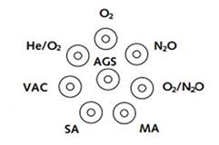
Figure 3.8. Circular array of outlets
- Mounting heights for terminal units should be between 900 mm and 1600 mm above finished floor level when installed on walls or similar vertical surfaces - the optimum height for the convenience of users of the medical gas system is 1400 mm.
Figure 3.9. Mounting heights and distances between centers of adjacent horizontal terminal units.
Note: Some in-patient accommodation is provided with terminal units installed in recesses behind covers/decorative panels, etc. To accommodate this, it is necessary to allow an additional 100 mm on each side of the outermost terminal units and 200 mm from center to top of recess and 300 mm from center to bottom of recess. The depth of the recess should be 150 mm. The surface should be clearly marked with suitable legend denoting medical equipment is installed within.
When installed in pendants or similar, outlets should be of a type suitable for mounting within the specified fitting.
3.3.3.2. Mounting distances for warning and alarm devices
|
Warning and alarm devices (local alarm panel, primary and secondary alarms, etc.) shall be located in positions subject to continuous 24-hour observation by personnel. They must be located so that they are easily observable and accessible by medical staff, with dimensions as illustrated: |
|
Figure 3.9. Mounting distances for warning devices
3.3.4. Electrical requirements
The electrical system supplying the medical gaseous oxygen system should be designed to ensure safe, continuous operation and compliance with medical standards. This section presents technical requirements for power supply, conductors, and system layout aimed at minimizing risks and optimizing performance.
General requirements:
Essential electrical supply: The medical gaseous oxygen system must be connected to an essential electrical supply, ensuring continuous around-the-clock operation, even in the event of a grid power failure.
Selection of wiring:
- Wiring systems should be selected with particular regard to the environment and risk from mechanical damage.
- PVC-insulated MICS (mineral insulated copper-sheathed) cable shall be used for external and internal locations.
- Heat-rated singles cable in galvanized conduit shall be used for plantrooms.
- For high-capacity devices, fire-rated steel wire armored cable may be appropriate to enhance safety.
Separation of electrical system and pipelines:
- Care should be taken to avoid occasional contact between pipework and electrical cables, conduit or trunking.
- When physical separation is impractical or contact with extraneous metalwork occurs (for example where the pipeline is carried in metal partitions, in technical shafts, or near metal bedhead units), the pipeline must strictly conform to regulations on earthing and equipotential bonding systems within the medical facility’s electrical wiring system, aimed at preventing static charge buildup and minimizing the risk of electrical discharge, ensuring safety for patients and medical staff.
Connection to devices:
- The final connection to any equipment, for example alarm panels or control panels, should be made via an unswitched fused connection unit.
- A double-pole switch should be available to permit maintenance or repair work on the equipment.
Arrangement in theatre pendants or enclosures:
- Where electrical systems and medical gas pipeline systems are enclosed in a (boom or rigid) pendant or multi-purpose-type enclosure, care should be taken to ensure that low voltage (LV), extra-low voltage (ELV) and communications and data systems are maintained together but separate from pipeline systems/that there should be no access to unprotected live parts within the pendant, in order to ensure safety.
3.3.5. Earthing
The medical oxygen pipeline system should be properly earthed to ensure safety, conform to medical standards, and prevent electrical risks. The requirements below are designed to ensure safe and effective operations.
Earthing the pipeline system: Pipelines should be bonded to the main earth terminal of the facility, in compliance with TCVN 9358:2012. This bonding should be made as near as possible to the point at which the pipeline enters the building from the plant.
Earthing conductors: The size of the bonding conductor should be in accordance with TCVN 9358:2012, ensuring safe and effective electrical conduction capability.
Restricting the use of pipelines as earthing systems: Medical gaseous oxygen pipelines should not themselves be used for earthing the electrical equipment or connecting electrical earthing equipment.
Connections at metal bedhead panels: Where a medical gas outlet or pipeline system is present within metal bedhead, the resistance of the bonding connection must be in accordance with the required values to ensure electrical safety and stable operation.
3.3.6. Regulations on alarm signals
Alarm signals at the oxygen supply area (e.g., liquid oxygen vessel or standby manifold system) should clearly display operational conditions to ensure safety and prompt handling. Below are the indicators and corresponding legends.
Table 3.8. Indicators of oxygen system operational conditions
|
Indicator |
Color |
Legend |
|
Normal |
Green |
The oxygen supply system is operating stably and normally. |
|
Low LOX capacity |
Yellow |
“LOX capacity low < 25%”: The liquid oxygen level in the main vessel has fallen below 25% of total capacity. A plan to refill oxygen shall be prepared. |
|
Supply changeover/LOX empty |
Yellow |
“LOX empty, standby in use”: The primary liquid oxygen vessel is depleted, the system has automatically switched to using the standby supply. Immediate oxygen refill is required to ensure continuous supply. |
|
Standby pressure low |
Red |
“Pressure in standby system < 50%”: The gas pressure in the standby oxygen cylinders has dropped below 50% of the full pressure. The standby cylinders should be refilled to maintain supply capability when needed. |
|
Pipeline pressure fault |
Red |
“Pipeline pressure fault”: Detected a serious pressure fault in the main pipeline conducting gas from the supply source. This could be excessively high or low pressure, requiring emergency inspection and handling to avoid supply interruptions or safety risks. |
Regulations on oxygen monitoring system parameters for PSA machines include: oxygen analyzers, oxygen concentration indicators, oxygen flow monitoring devices, oxygen concentration/flow recorders. In cases where the oxygen concentration drops below 90%, the monitoring system should isolate the PSA plant from the pipeline gas distribution system so the emergency/reserve manifold goes into operation.
CHAPTER IV: SYSTEM INSTALLATION AND MAINTENANCE
4.1. Installation
The installation and operation of the medical oxygen supply system must fully comply with applicable law regulations, including technical standards, technical regulations, regulations on occupational safety, and fire and explosion prevention. The system must be installed using suitable materials, correct techniques, and have periodic inspection and maintenance measures to ensure safety and effectiveness during use.
Applicable technical standards and regulations:
- TCVN 7742:2007 (ISO 10083:2006) - Requirements for the design and installation of an oxygen concentrator supply system for use with a medical gas pipeline distribution system, applying to oxygen concentrator supply systems that produce oxygen-enriched air with an oxygen concentration ≥ 90%.
- TCVN 8022-1:2009 (ISO 7396-1:2007) - Regulations on medical gas pipeline systems (including compressed medical gases and vacuum) with guidelines on design, installation, operation, and maintenance to minimize risks and ensure safety.
- TCVN 6153:1996 - Pressure vessels - Technical safety requirements for design.
- TCVN 6155:1996 - Pressure vessels - Technical safety requirements for installation, use, and repair.
- TCVN 6156:1996 - Pressure vessels - Hydraulic testing methods.
- TCVN 5507:2002 - Hazardous chemicals - Code of practice for safety in production, commerce, use, handing and transportation (applies to liquid oxygen safety).
Primary technical requirements during installation:
- Only materials and equipment conforming to the standards (having conformity certification or equivalent) shall be used.
- Oxygen pipelines must be made of compatible materials (usually copper or stainless steel). Materials that can react with oxygen must not be used.
- An area valve service system must be provided to isolate each branch during maintenance or incident response.
- High/low-pressure warning devices and oxygen leak warnings must be installed.
- All welds and joints must undergo non-destructive testing and leak testing before commissioning.
Requirements to operate the system safely:
- Only trained personnel are permitted to operate the medical gas system.
- Parameters (pressure, flow rate, gas level indicators etc.) must be checked before supplying oxygen to usage areas.
- Main valves, pressure regulators, or pipelines must not be arbitrarily adjusted.
- It must be ensured that the area housing the oxygen supply is always well-ventilated, free of flammable materials, and avoids electrical sparks.
- The low-pressure, gas leak, or source loss warning lights/alarms must be regularly checked.
- Gloves and protective gear must be worn when handling oxygen cylinders or related equipment.
4.2. System maintenance
Maintenance of the medical oxygen supply system is a mandatory requirement to ensure stable, continuous, and safe operations. Maintenance work must comply with the manufacturer's guidelines, technical standards, and relevant law regulations.
- TCVN 7742:2007 (ISO 10083:2006) - Requirements for the design, installation, and maintenance of oxygen concentrator supply systems for use with medical gas pipeline systems.
- TCVN 8022-1:2009 (ISO 7396-1:2007) - Regulations on medical gas pipeline systems (including compressed medical gases and vacuum) with guidelines on design, installation, operation, and maintenance to minimize risks and ensure safety.
- Decree No. 98/2021/ND-CP - Principles for management and use of medical devices; mandating medical device trading establishments to provide full user manuals and conditions to ensure safety, preservation, calibration, inspection, servicing, and maintenance.
Periodic inspection procedures:
Daily:
- Check system pressure and oxygen levels in the vessel/cylinders.
- Check the operation of the alarm system and outlets.
- Ensure there are no gas leaks (by listening, smelling, or using soap bubbles to check).
Weekly:
- Check the operation of AVSUs (area valve service units).
- Check and clean flowmeters and humidifiers.
- Record pressure parameters at each usage area.
Quarterly or every 6 months:
- Inspect all pipelines, accessories, and pressure regulators.
- Measure output oxygen purity if equipment is available.
- Inspect the electrical system, anti-static earthing.
4.3. Documentation of operation records and maintenance logs
Each system should have its own management documentation, including:
- Schematic diagram of the medical gas system (updated after every change).
- Daily operation log: Pressure, oxygen amount, minor incidents.
- Periodic inspection records: Confirmed by the technical department.
- Schedule for periodic maintenance and component replacement.
- Operation/maintenance manuals for each device.
- Forms for managing operation, periodic maintenance (logbooks, inspection sheets etc.); Appendix of operational inspection forms; Appendix of procedures for initial commissioning and inspection after installation etc.
4.4. Technical safety inspection of the medical oxygen system
The medical oxygen system must be inspected by a qualified entity before being put into use. The inspection covers:
- Pressure pipeline systems
- Liquid oxygen storage vessels
- Pressure gauges, pressure regulating valves
Periodic inspection shall be in accordance with Circular No. 36/2019/TT-BLDTBXH of the Ministry of Labor, Invalids and Social Affairs and replacements (if any). The inspection results constitute an integral part of the system's commissioning and operational documentation.
4.5. Specific risks when using liquid oxygen systems
The use of oxygen in a liquid state entails certain specific risks, which should be identified with appropriate preventive measures in place. Situations prone to causing cold burns include:
- Connecting or disconnecting joints, liquid oxygen supply valves.
- Depressurizing or venting excess gas at the LOX vessel.
- Leaks, liquid oxygen spills outside due to equipment failure or incorrect manipulation.
- Risk of tripping if spilled liquid oxygen causes the floor surface to freeze.
All personnel assigned to operate the liquid oxygen system must be fully equipped with personal protective equipment.
A sign “WARNING - LIQUID OXYGEN - COLD BURN HAZARD” shall be displayed at the LOX storage area.
Only personnel with specialized training in medical gases and cryogenic gas handling are permitted to perform operations.
Force must absolutely not be used, and steps must not be performed out of sequence while operating the LOX system. When operating, it must be ensured that the valve system, pressure gauges, and pipelines are always dry and not leaking.
Scenarios must be developed, and periodic drills must be organized for responding to liquid oxygen leak incidents.
CHAPTER V: EMERGENCY RESPONSE
5.1. Common emergencies
- Cessation of oxygen supply for the entire facility or an area.
- Fire or explosion at the oxygen cylinder/vessel storage area.
- Oxygen leak at a treatment area or technical station.
- Failure of terminal devices (flowmeter, ventilator, humidifier etc.).
- Sudden power loss at the oxygen station or pressure regulation area.
5.2. Emergency response
Responding to emergency situations in a medical oxygen supply system requires a strict procedure to ensure safety for patients and medical staff. Below are the basic steps to implement:
Identify the emergency situation: Early detection of incidents such as leaks, pressure drops, or malfunctions in the oxygen supply system. This procedure should be widely disseminated, and staff should be trained periodically to ensure the ability to detect and respond promptly to emergency situations.
The main tasks include: Detect abnormalities in the system; Collect initial information; Activate the alarm system; Assess the emergency level (Low level: Minor incident not affecting system operations (e.g., secondary valve failure, needs repair), Medium level: Incident causing localized interruption or posing a risk of gas leak, High level: Serious incident threatening the safety of the entire system (e.g., fire, explosion, total pressure loss), and then decide whether to evacuate the area or disconnect the system); Determine the root cause of the incident; Report the situation; Prepare to respond to the incident.
Note: This procedure should be widely disseminated, and staff should be trained periodically to ensure the ability to detect and respond promptly to emergency situations.
- Activate alarm: Use the alarm system to notify all staff of the incident, ensuring everyone is aware and prepared to respond.
- Disconnect the source of supply: In the event of a leak or danger, disconnect the oxygen supply source to prevent the risk of fire, explosion, or other accidents.
- Evacuate affected area: Move patients and staff out of the danger area to ensure safety. Specific tasks are as follows: Evaluate the danger level, identify the directly affected area and the area needing evacuation; Activate the emergency alarm system (if any); Immediately notify all staff and patients in the affected area; Guide evacuation via the internal PA system or by clear alarm signals; Deploy the emergency response team for support; Prioritize patient evacuation, move patients using medical oxygen to a safe area or switch them to a standby oxygen supply source; Guide staff to leave the affected area following predefined escape routes; Close doors to the area to prevent gaseous oxygen or hazards from spreading (if safe to do so); Assign technical staff to monitor the danger area until the incident is resolved.
- Contact the emergency response team: Immediately call the emergency response team or functional authorities for support in handling the incident.
- Personal Protective Equipment (PPE): Staff participating in incident response must be fully equipped with PPE to protect their safety. Specific tasks are as follows: Identify related risks (e.g., oxygen leak, high pressure, or fire/explosion risk); Select appropriate PPE, including chemical or heat-resistant gloves, safety goggles or face shields, anti-static or heat-resistant clothing, gas filtering masks if working in confined spaces; Check PPE for integrity (no tears, holes, damage); Ensure the size and condition of PPE fit the user; Don or wear PPE in the correct sequence; Ensure PPE is worn tightly, without loosening or shifting during work; Avoid actions that could damage PPE (e.g., contact with sharp surfaces, abrasive substances); Maintain a safe distance from heat sources or sparks; Doff PPE in the reverse sequence to donning; Dispose of single-use PPE according to hazardous waste management regulations; Clean and store reusable PPE correctly.
- Evaluate and remedy the incident: Determine the cause and implement necessary repair measures to restore the system. Specific tasks are as follows: Conduct a physical inspection of the system; Analyze the causes leading to the incident; Determine the impact level of the incident; Perform repairs and remediation following correct procedures; Re-inspect the entire system before bringing it back into operation.
- Report and record the incident: Formulate a detailed report on the incident, its causes, remedies, and improvement proposals to prevent recurrence. The report includes particulars regarding: details of the incident; its causes and remedies; improvement proposals to prevent incident recurrence, etc.
You are not logged in.
This feature is available to Advanced account holders. Please log in to access detailed information on Related documents.
If you do not have an account, please register here!
VIETNAMESE DOCUMENTS
This utility is available to subscribers only. Please log in to a subscriber account to download. Don’t have an account? Register here
This utility is available to subscribers only. Please log in to a subscriber account to download. Don’t have an account? Register here
ENGLISH DOCUMENTS
This utility is available to subscribers only. Please log in to a subscriber account to download. Don’t have an account? Register here
This utility is available to subscribers only. Please log in to a subscriber account to download. Don’t have an account? Register here

