Circular 21/2022/TT-BTTTT on promulgation of National technical regulations on electromagnetic exposure of public land mobile base stations
- Summary
- Content
- Status
- Vietnamese
- Related documents
- Diagram
- Download
Please log in to your Advanced Package to view the full text. Do not have an account yet? Register here.
Please log in to use this function
Please log in to use this function
ATTRIBUTE
| Issuing body: | Ministry of Information and Communications | Effective date: | Known Please log in to a subscriber account to use this function. Don’t have an account? Register here |
| Official number: | 21/2022/TT-BTTTT | Signer: | Nguyen Manh Hung |
| Type: | Circular | Expiry date: | Updating |
| Issuing date: | 29/11/2022 | Effect status: | Known Please log in to a subscriber account to use this function. Don’t have an account? Register here |
| Fields: | Information - Communications |
The Effect status of this document is known.This feature is available to Advanced account holders. Please log in to a subscriber account to view Effect status. Don’t have an account? Register here
THE MINISTRY OF INFORMATION AND COMMUNICATIONS ------------------ No. 21/2022/TT-BTTTT | THE SOCIALIST REPUBLIC OF VIETNAM Independence - Freedom - Happiness ------------------ Hanoi, November 29, 2022 |
CIRCULAR
Promulgation of "National technical regulations on electromagnetic exposure of public land mobile base stations"
------------------
Pursuant to the Law on Standards and Technical Regulations dated June 29, 2006;
Pursuant to the Law on Telecommunications dated November 23, 2009;
Pursuant to the Law on Radio Frequency dated November 23, 2009;
Pursuant to Decree No. 127/2007/ND-CP dated August 1, 2007 of the Government detailing and guiding the implementation of a number of articles of the Law on Standards and Technical Regulations;
Pursuant to Decree No. 78/2018/ND-CP dated May 16, 2018 of the Government amending and supplementing a number of articles of Decree No. 127/2007/ND-CP dated August 1, 2007 of the Government detailing the implementation of a number of articles of the Law on Standards and Technical Regulations;
Pursuant to Decree No. 48/2022/ND-CP dated July 26, 2022 of the Government regulating the functions, tasks, powers and organizational structure of the Ministry of Information and Communications;
At the request of the Director of the Department of Science and Technology,
The Minister of Information and Communications promulgates a Circular regulating national technical regulations on electromagnetic field exposure of public land mobile base stations.
Article 1. Issue the National Technical Regulation on electromagnetic exposure of public land mobile base stations (QCVN 8:2022/BTTTT) together with this Circular is.
Article 2. Effectiveness of implementation
1. This Circular takes effect from July 1, 2023.
2. National technical regulation on electromagnetic field exposure of public land mobile base stations, Symbol QCVN 8:2010/BTTTT is prescribed in Clause 7, Article 1, Circular No. 18/2010/TT-BTTTT dated July 30, 2010 of the Minister of Information and Communications promulgating National Technical Regulations on telecommunications expires from July 1, 2023.
Article 3. Certificates of public land mobile base station inspection that have been issued before the effective date of this Circular and are still valid will continue to be applied until the end of the validity period stated in Certificates of inspection.
Article 4. Chief of Office, Director of the Department of Science and Technology, Heads of agencies and units under the Ministry of Information and Communications, Directors of Departments of Information and Communications of provinces and centrally run cities and Relevant organizations and individuals are responsible for implementing this Circular.
| MINISTER
(Signed and sealed)
Nguyen Manh Hung |

SOCIALIST REPUBLIC OF VIETNAM
QCVN 8:2022/BTTTT
NATIONAL TECHNICAL REGULATION ON ELECTROMAGNETIC EXPOSURE FROM PUBLIC LAND MOBILE BASE STATIONS
HANOI – 2022
Preface
QCVN 8:2022/BTTTT replaces QCVN 8:2010/BTTTT.
The technical requirements and measurement methods of QCVN 8:2022/BTTTT are built on the basis of IEC 62232:2017, ITU T K.100 (July 2019), ITU-T K.52 (January 2018), TCVN 3718- 1:2005 and ICNIRP Guidelines “Guidelines for limiting exposure to electromagnetic fields (100 KHz to 300 GHz).
QCVN 8:2022/BTTTT was compiled by the Department of Telecommunications, appraised by the Ministry of Science and Technology, submitted for approval by the Department of Science and Technology, and issued by the Minister of Information and Communications together with Circular No. 21/2022/ TT-BTTTT dated November 29, 2022.
NATIONAL TECHNICAL REGULATION ON ELECTROMAGNETIC EXPOSURE FROM PUBLIC LAND MOBILE BASE STATIONS
1. GENERAL PROVISIONS
1.1. Scope
This regulation applies to public land mobile base stations with antennas installed outdoors, operating in the frequency range from 110 MHz to 6 GHz.
1.2. Applicable subjects
This regulation applies to agencies, organizations and businesses that have mobile base stations that transmit mobile information signals in the territory of Vietnam.
1.3. References
IEC 62232:2017 “Determination of RF field strength, power density and SAR in the vicinity of radio communication base stations for the purpose of evaluating human exposure”.
1.4. Abbreviation
E | Electrical field strength | Volts per meter (V/m) |
H | Cường độ trường từ | Ampere per meter (A/m) |
S | Power density | Watt per square meter (W/m2) |
f | Frequency | Ha (Hz) |
SAR | Specific absorption level | Oát trên kilôgam (W/kg) |
λ | Wavelength | Meter (m) |
C | Speed of light in vacuum | 2.997 X 10⁸ m/s |
η0 | Intrinsic impedance of free space | 120 ΠΩ (-377 Ω) |
1.5. Interpretation
1.5.1. Antenna
Device that converts energy between a guided wave (e.g. in a coaxial cable) and a free-space wave, or/and vice versa. Antennas can be used to transmit and/or receive radio signals;
In this Regulation, if there is no specific regulation, the term antenna is used to refer to the transmitting antenna.
1.5.2. Transmitter
Device that transmits radio frequencies and is connected to an antenna for information transmission purposes.
1.5.3. Base station (BS)
Fixed equipment used to transmit radio waves used in public land mobile networks. For the purposes of this Regulation, the term base station includes radio transmitters and associated antennas.
1.5.4. Equipment under test (EUT)
The base station must be measured according to the measurement method specified in this Regulation.
1.5.5. Relevant Source (RS)
Radio radiation sources in the frequency range from 100 KHz to 6 GHz have an exposure rate greater than 0.05 at a specified measurement point (Pl).
1.5.6. Isotropy
Physical properties do not change in all directions.
1.5.7. Horizontal omnidirectional antenna
A type of radio antenna that radiates power equally in all directions in the horizontal plane.
1.5.8. Directivity antenna:
A type of antenna that radiates radio power in a certain direction.
1.5.9. Smart antenna
This type of antenna emits a narrow beam simultaneously aimed at individual users to optimize communications with instantaneous power radiation direction adjustment for each individual communication channel. Smart antennas include single antennas (MIMO) or antennas integrating multiple radiating elements on a radiating surface (mMIMO).
1.5.10. Equivalent Isotropic Radiated Power (ElRP)
The time-average equivalent isotropic radiant power is determined by the formula:
![]()
The nominal equivalent isotropic radiant power is determined by the formula:
![]()
Or ![]()
In which:
- EIRP(W): average equivalent isotropic radiant power, unit watt;
- EIRPt(W): nominal equivalent isotropic radiant power, unit watt;
- EIRPt(dBm): nominal equivalent isotropic radiated power, unit decibel;
- Pt(W): total output power of generators, unit watt;
- pt (dBm): total output power of the generators, unit decibel;
- L(dB): total loss from the transmitter to the antenna (eg due to combiner, feeder...);
- G(dBi): maximum gain of the antenna corresponding to an isotropic antenna;
- Ft Average emission coefficient over time.
For the base station, a conventional radiating antenna Ft = 1 is used.
For base stations using smart radiation antennas Ft = 0.233.
1.5.11. Electric field strength (E)
The magnitude of the field vector at a point, determined by the force F per unit charge q divided by that charge:

The electric field strength has a unit of v/m.
1.5.12. Magnetic field strength (H)
Magnitude of the field vector at a point caused by electrostatic force F on charge q moving with speed v:
![]()
Magnetic field strength has units of A/m.
1.5.13. Point of Investigation (PI)
The location within the Domain of Investigation (DI) where the electric field E, magnetic field H or power density S values are measured.
1.5.14. Reference Point (RP)
For plate antennas, the reference point is the center of the rear reflector. For horizontal isotropic antennas, the reference point is the center of the antenna.
1.5.15. Compliance Boundary (CB)
The compliance boundary of the EUT is the limit boundary around the transmitting antenna of the EUT, outside which the exposure level caused by the EUT is less than the allowable limit exposure level (not taking into account the influence of other radiation sources).
The EUT domain of compliance is the volume enclosed by the compliance boundary, which is not accessible to the public.
1.5.16. Relevant domain (RD)
The area around an antenna in which the exposure ratio due to that antenna is greater than 0.05
1.5.17. Public Access (PA)
A place where people's travel and living activities can take place under normal conditions.
1.5.18. Domain of Investigation (DI)
Zoning of the Relevant domain where people can access when the base station has been put into operation.
1.5.19. Power density (S)
Radiant power incident perpendicular to a surface, divided by the area of that surface. Power density has a unit of w/m2.
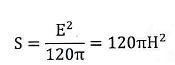
1.5.20. Equivalent plane wave power density
The power per unit area normalized to the direction of propagation of a plane wave in free space is expressed by:
1.5.21. Exposure level
Exposure limits are used for comparison with exposure values. In the frequency range from 100 KHz to 6 GHz, exposure limits can be values of electric field strength, magnetic field strength or power density.
1.5.22. Specific Absorption Rate (SAR)
The rate over time at which RF energy is delivered into a unit of biological mass, expressed in Watts per kilogram (W/kg).
1.5.23. Exposure
Phenomenon that occurs when humans are exposed to an RF field or exposed current.
1.5.24. Non-occupational exposure
Non-occupational exposure is exposure to humans, not during work or on the job.
1.5.25. Intrinsic impedance of free space
The ratio between the electric field intensity and the magnetic field intensity of electromagnetic waves propagating in space. The characteristic impedance of a plane wave in free space (free space impedance) is approximately 377 Ω (or 120 ΠΩ).
1.5.26. Exposure Ratio
Parameter evaluated at a specified location for each radio source operating frequency, expressed as the ratio of the equivalent plane wave power density to the corresponding exposure limit.
In the frequency range from 100 KHz to 6 GHz:
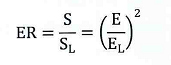
In which:
- ER: exposure rate at each operating frequency of the source;
- f: operating frequency of the source;
- S: equivalent plane wave power density measured at frequency f of the source;
- SL: exposure limit derived in terms of equivalent plane wave power density at frequency f.
- E: electric field intensity measured at frequency f of the source;
- EL: exposure limit derived in terms of electric field streng at frequency/.
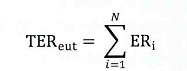
1.5.27. Total Exposure Ratio (TER)
The total exposure rate of the EUT alone is the maximum of the sum of the exposure values of the EUT regardless of relevant exposure sources.
For multi-band (N-band) EUT:
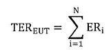
Maximum value of the sum of the exposure values of the EUT and all associated sources in the frequency range 100 KHz to 6 GHz:
![]()
In which:
- ERi: exposure rate of band i;
- TEREUT: exposure rate of EUT;
- TERRS: exposure rate of all relevant sources.
2. TECHNICAL REGULATIONS
2.1. Non-occupational exposure limits
Non-occupational exposure limits for the frequency range of public land mobile base stations must comply with Table 1 as follows:
Table 1 - Non-occupational exposure limits
Frequency range | Electric field strength (V/m) | Magnetic strength (A/m) | Equivalent plane wave power density (W/m2) |
100 kHz -1 MHz | 87 | 0,23/ f0.5 | - |
1 MHz-10 MHz | 87/ f0.5 | 0,23/ f0.5 | - |
10 MHz-6 GHz | 27,5 | 0,073 | 2 |
2.2. Method for determining total exposure rate
This section prescribes the method of determining the total exposure rate in Relevant domains accessible to the public.
2.2.1. Method description
The total exposure rate was determined according to the flow chart Figure 1.
The cycle in Figure 1 is performed in three steps as follows to determine the total exposure rate:
- Step 1: determine the base station's domain of compliance according to 2.3.1. If people can access the space within the compliance boundary (domain of compliance), the total exposure ratio will be greater than 1;
Step 2: determine the Relevant domain and Domain of Investigation according to 2.3.3 and 2.3.4. If people do not have access to the Relevant domain, i.e. no Domain of Investigation exists, then the total exposure ratio will be less than or equal to 1;
- Step 3: determine the total exposure rate in the Domain of Investigation according to 2.2.2.
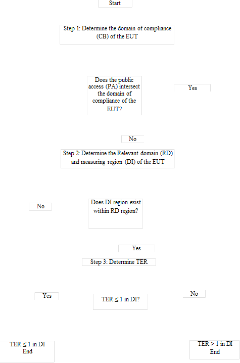
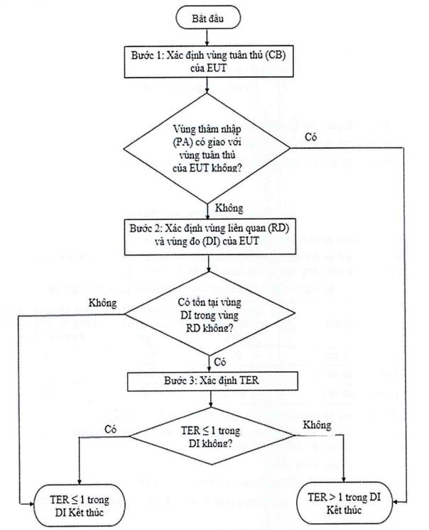
Figure 1 - Flow chart for assessing total exposure rate
2.2.2. Comprehensive assessment of total exposure rates
Comprehensive assessment of total exposure rates aims to determine the greatest total exposure rates in assessment areas that are accessible to the public (i.e., measurement zones).
If the operator establishes the boundaries of a restricted area to prevent public access to the area surrounding the EUT and/or related sources then the assessment must be performed at measuring points (Pl) located close to these boundaries (see Figure 2).
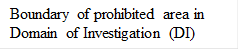
Figure 2 - Physical boundary of the prohibited area within the Domain of Investigation
The total exposure rate is determined at the measurement points (Pl, see 1.5.26) using the method described in 2.4 and 2.5. The maximum sampling step (distance between measurement points) is 2 m. The set of measuring points must form a grid with a square mesh with a maximum size of 2 m X 2 m.
![]()
![]()
![]()
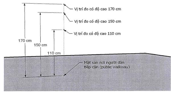
Figure 3 - Three measuring positions at each measuring point
At each measurement point, the total exposure rate is determined as the maximum value of the total exposure rate values measured at measurement locations that are 110 cm, 150 cm and 170 cm above the floor level where people approach and are within the Domain of Investigation (DI) as illustrated in Figure 3.
2.3. Method for determining zones
2.3.1. Domain of compliance
The domain of compliance of the antenna is isotropic in the horizontal direction
|
|
a) The antenna horizontal plane is isotropic in the horizontal direction | b) The vertical plane of the antenna is isotropic in the horizontal direction |

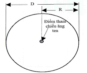
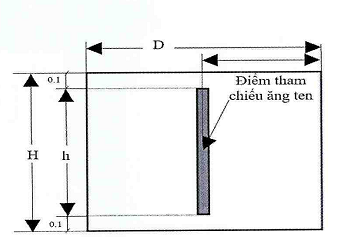
Figure 4 - Compliant region of an isotropic antenna in the horizontal direction
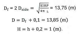
The domain of compliance of a horizontally isotropic antenna is a circular cylinder (diameter D) and the height is equal to the length of the antenna radiating surface plus 0.2 m, extend 0.1 m to the top and bottom of the antenna (H = h + 0.2m). This cylinder has an axis that coincides with the axis of the antenna (see Figure 4) .
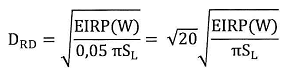
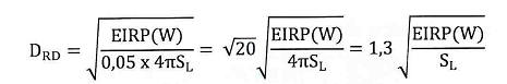
The formula for determining the diameter of the domain of compliance of a horizontally oriented antenna (see Appendix A) is as follows:
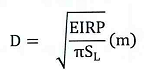
In which:
- EIRP (W): equivalent isotropic radiated power of the antenna;
- SL(W/m2): Non-occupational exposure limit derived in terms of equivalent plane wave power density (W/m2), for base stations applying the frequency range from 110 MHz to 6 GHz is calculated in 2 w/m2
- D: diameter of the cylinder (diameter of the domain of compliance);
- H (m): height of the cylinder (height of the domain of compliance), calculated in h + 0.2 m;
- h: length of the radiation surface of the antenna.
Domain of compliance of directional antenna
|
|
a) Horizontal plane of directional antenna domain of compliance | b) Vertical plane of directional antenna domain of compliance |
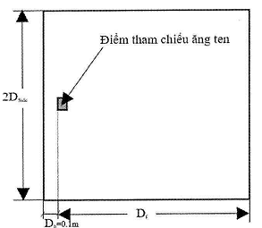
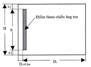
Figure 5 - Domain of compliance of directional antenna
The domain of compliance of a directional antenna is a rectangular box with a rectangular base (length D, width Df or 2Dside) and a height equal to the length of the antenna radiating surface plus 0.2 m, extend 0.1 m to the top and bottom of the antenna (H = h + 0.2 m). This box starts 0.1 m behind the antenna and has an axis parallel to the antenna axis (see Figure 5).
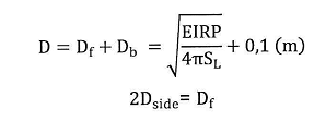
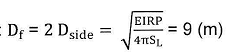
The formula for determining the size of the domain of compliance of a directional antenna (see Appendix A) is as follows:
In which:
- EIRP(W): Average equivalent isotropic radiated power of the antenna;
- SL(W/m2): Non-occupational exposure limit derived in the form of equivalent plane wave power density (W/m2), for BS applying the frequency range from 110 MHz to 6 GHz calculated in 2 w/m2;
- D (m): length of the bottom edge of the box;
- 2Dside: Width of the bottom edge of the box;
- H (m): height of the box (height of the domain of compliance), calculated in h + 0.2 m;
- Db (m): distance from the antenna reference point to the domain of compliance boundary behind the antenna is 0.1 m;
- Df (m): distance from the antenna reference point to the domain of compliance boundary in front of the antenna (main broadcast direction);
- h: length of the radiation surface of the antenna.
2.3.2. Public access
The public access is defined by a space(s) with a floor-level bottom where people can access and a height of 170 cm (see Figure 6).
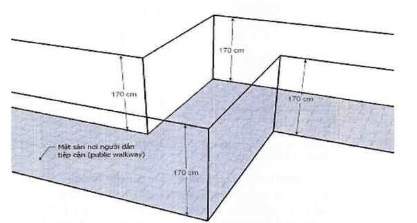
Figure 6 - Illustration of the public access
2.3.3. Related area
2.3.3.1. The Relevant domain of the antenna is isotropic in the horizontal direction
|
|
a) Horizontal plane of the Relevant domain of an isotropic antenna in the horizontal direction | b) Vertical plane of the Relevant domain of the horizontally isotropic antenna |

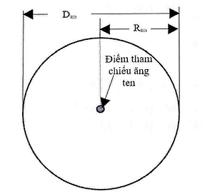
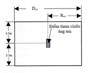
Figure 7 - Relevant domain of a horizontal isotropic antenna
The Relevant domain of a horizontally isotropic antenna is a circular cylinder whose diameter is DRD and height is HRD (see Figure 7).
For single-band antennas:
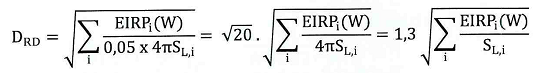
For multi-band antennas:
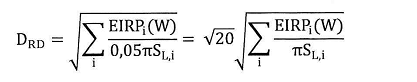
In which:
- DRD: diameter of Relevant domain (m);
- D: domain of compliance radius (see 2.3.1);
- HRD: height of Relevant domain (m), calculated in 7 m;
- EIRP(W): equivalent isotropic radiant power (W);
- EIRPi(W): equivalent isotropic radiated power of band i (W);
- SL: non-occupational exposure limit derived in the form of equivalent plane wave power density (W/m2), for BS applied in the frequency range from 110 MHz to 6 GHz calculated as 2 w/ m2;
- SL,i: non-occupational exposure limit derived as equivalent plane wave power density of band i (W/m2), for BS applied in the frequency range from 110 MHz to 6 GHz, calculated as 2 w/m2.
2.3.3.2. Relevant domain of directional antenna
|
|
a) Horizontal plane of the Relevant domain of an isotropic antenna | b) Vertical plane of the Relevant domain of an isotropic antenna |
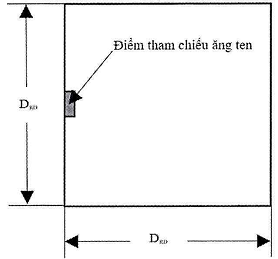
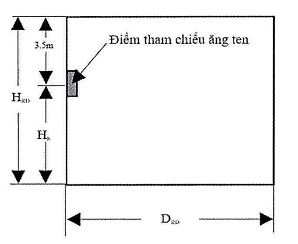
Figure 8 - Relevant domain of directional antenna
The Relevant domain of a directional antenna is box-shaped in the main broadcasting direction of the antenna, the length is DRD, the width is DRD and the height is HRD (see Figure 8).
For single-band antennas:
For multi-band antennas:
In which:
- DRD: base size of the Relevant domain (m);
- Df (m): distance from the antenna reference point to the domain of compliance boundary in front of the antenna (see 2.3.1);
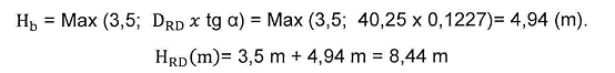
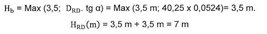
- HRD: height of Relevant domain (m);
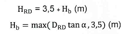
- Hb: height calculated from the reference point of the antenna to the lower edge of the Relevant domain (m);
- EIRP (W): average equivalent isotropic radiant power (W);
- EIRPi(W): average equivalent isotropic radiated power of the band
- SL(W/m2): non-occupational exposure limit derived in the form of equivalent plane wave power density (W/m2), for B8 applying the frequency range from 110 MHz to 6 GHz calculated as 2 w/m2;
- SL,i: non-occupational exposure limit derived in the form of equivalent plane wave power density of band i (W/m2), for BS applying the frequency range from 110 MHz to 6 GHz calculated as 2w/m2;
- a: total elevation angle (electrical + mechanical) in degrees;
- In case a cannot be determined, it can be calculated in π/15 radians (12 °), this is the maximum practical elevation angle selected to ensure the most stringent results. The height of 3.5 m is also chosen to correspond to the actual Hb height for antennas without elevation angle;
- The above formulas are applied to antennas tilted down. If the antenna is tilted upward, the values 3.5 m and Hb will be swapped.
2.3.4. Domain of Investigation (DI)
The Domain of Investigation is a sub-area of the Relevant domain and accessible to the public, which is the intersection between the Relevant domain and the public access of the base station (see Figure 9).
![]()

![]()
![]()
![]()
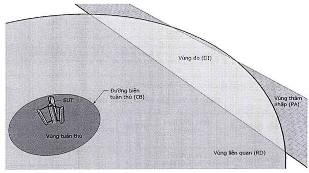
Figure 9 - Illustration of the Domain of Investigation of an isotropic antenna in the horizontal direction
2.4. Measurement methods
2.4.1. General requirements
A broadband or frequency-selective meter consisting of one or more probes may be used to measure field strength to determine the ER exposure rate. The measurement and processing system must cover at least the frequency range from 100 KHz to 6 GHz and higher if required.
The radiated power of the EUT at the time of measurement requires maximum transmission.
2.4.2. Requirements for measuring equipment
The equipment used for testing shall be calibrated at a number of frequencies sufficient to achieve the declared measurement uncertainty of the equipment over the measurement frequency range. Calibration of the entire system or calibration of all individual parts of the system can be performed. In cases where a specific demodulation capability is used, the measuring device must also be calibrated for the parameters of interest (e.g., for WCDMA, CPICH signals, and volume signals).
Broadband measurement systems are required in Table 2.
Table 2 - Requirements for broadband measurement systems
Frequency response | Minimum detection level | Dynamic range | Linearity | Isotropic properties of the probe | |
From 900 MHz to 3 GHz±1.5dB | < 2 mW/m2 | > 40 dB | ± 1.5 dB | < 2.5 dB for isotropic probes | |
Less than 900 MHz and greater than 3 GHz ±3dB | (e.g. 1 V/m or 0.003 A/m) |
|
|
| |
Measurement antennas and probes (Probes) with an isotropic response are recommended. Single axis (e.g. dipole dipole) and directional measurement antennas are permitted provided that the measurement is post-processed to obtain the total field strength (equivalent to testing with an isotropic probe/antenna). |
| ||||
Frequency selective measurement systems are required in Table 3.
Table 3 - Requirements for frequency selective measurement system
Frequency response | Minimum detection level | Dynamic range | Linearity | Isotropic properties of the probe |
From 900 MHz to 3 GHz ± 1.5dB Less than 900 MHz | < 0.01 mW/m2 (Example: 0.06 v/m) Signal to noise ratio is at least 10 dB over the test bandwidth | >60dB | ± 1,5 dB | Less than 900 MHz: < 2 dB From 900 MHz-3 GHz: <3 dB Greater than 3Gz: < 5 dB |
and greater than 3 GHz ± 3 dB | ||||
Measurement antennas and probes with an isotropic response are recommended. Single axis (e.g. dipole dipole) and directional measurement antennas are permitted provided that the measurement is post-processed to obtain the total field strength (equivalent to testing with an isotropic probe/antenna) | ||||
2.4.3. Broadband measurements
2.4.3.1. Applicability of broadband measurement
Broadband measurements give the sum of all signals across the probe's frequency range without distinguishing the contributions of different frequencies (from the EUT or from ambient sources). They can give instantaneous or time-averaged field strength values.
This method gives the field strength at the time of observation and is suitable for monitoring field strength.
Broadband measurements are suitable for determining overall levels in the environment.
Extrapolation of broadband measurement results is not recommended. Such extrapolation may lead to results exceeding the actual value depending on the characteristics of the probe and the characteristics of the EUT/surrounding signal. Therefore, frequency selective measurements are recommended when accurate extrapolation is required.
2.4.3.2. Broadband measurement method
The isotropic broadband survey instrument was selected to have a suitable measurement range from 100 KHz to 6 GHz to measure RF field strength and meet the requirements of the broadband device.
The frequency response of the probe shall be either flat within the required frequency range of Table 2 or shall be the inverse of the relevant frequency-dependent exposure limit to provide direct readability expressed in terms of the relevant exposure rate, for example as a percentage of the limit.
2.4.4. Frequency selection measurement
2.4.4.1. Possibility of applying frequency-selective measurements
Frequency selective measurements use spectrum analysis or channel decoding techniques to separate and identify the base station source and the surrounding frequencies used:
• To differentiate signals at different frequencies;
• When the surrounding fields are comparable to the level of the base station source or exceed the level of the base station source;
• When information is needed to allow accurate extrapolation from the evaluation profile to the quantitative profile;
• In the case of local RF exposure quantification, when the power density level exceeds a certain threshold.
2.4.4.2. Frequency selection measurement method
When using a frequency-selective measuring device, make sure it covers the frequency range of the signals being evaluated. Measurement over a wide frequency range may in some cases require more than one measurement antenna.
Measurement of RF field strength must consider contributions from all directions/polarizations. Using an omnidirectional antenna is most suitable for this measurement. Other antennas may be used according to the following regulations.
• Single axis (e.g. dipole dipole) can be used to obtain the total RF field strength by positioning the probe in three orthogonal directions and summing the measured results.
• An isotropic measuring probe or antenna can be used to separate contributions from different directions. These contributions will be summed to determine the total field strength. However, this value will be higher than the true value.
• Directional antennas can be used for handheld scanning provided they are oriented to read the maximum RF field strength value.
The correlation between results obtained using isotropic and anisotropic antennas can be affected by the presence of strong multipath signals.
Perform an initial broad spectrum scan to identify signals of interest for subsequent analysis.
For signals of interest (e.g., high levels), increase measurement resolution by focusing on the signal frequency and performing individual measurements of each signal.
Each relevant frequency band to be measured must be analyzed to determine the optimal settings for the frequency selective meter. The resolution bandwidth setting must take into account the base station signals and appropriate surrounding fields.
2.4.5. Determination of the Total Exposure Rate of the EUT (TEReut) value
The total exposure of the EUT is calculated as the sum of the exposure ratios of the transmit frequency bands of the EUT. The total exposure value is determined as the maximum value measured in the DI Domain of Investigation:
In which:
ERi is the exposure rate of band i;
TEReut: total EUT exposure rate, for single-band equipment;
TEReut=EReut.
According to the provisions in 2.2.2, at each measurement point, the ERi value is determined at 3 locations and the largest value is taken.
2.5. Assess total exposure rate
The total exposure rate at the measurement point (Pl) is the sum of the M measured ER values over the entire frequency range from 100 KHz to 6 GHz:
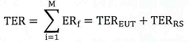
In which:
ERf: exposure rate at frequency f with value > 0.05;
TER: total exposure rate at the measurement point;
TEREUT: total exposure rate of EUT;
TERRS: total exposure rate of RS.
If the total exposure rate is less than or equal to one (TER<Í), the base station complies with the non-occupational exposure limit requirement.
If the total exposure ratio is greater than one (TER>I), the base station is not in compliance with the non-occupational exposure limit requirement.
3. REGULATIONS FOR MANAGEMENT
3.1. Public land mobile base stations must comply with the provisions of this Regulation.
3.2. Measuring devices and measuring equipment: comply with the provisions of measurement law.
4. RESPONSIBILITIES OF ORGANIZATIONS AND INDIVIDUALS
Telecommunications enterprises are responsible for ensuring that public land mobile base stations comply with this Regulation and are subject to inspection by state management agencies according to current regulations.
5. IMPLEMENTATION ORGANIZATION
5.1. The Department of Telecommunications and the Departments of Information and Communications are responsible for guiding and organizing the implementation and management of public land mobile base stations according to this Regulation.
5.2. This regulation is applied to replace QCVN 8:2010/BTTTT, National Technical Regulation on electromagnetic exposure of public land mobile base stations.
5.3. In case the regulations stated in this Regulation are changed, supplemented or replaced, the provisions in the new document shall comply.
5.4. During the implementation of this Regulation, if any problems or difficulties arise, relevant organizations and individuals should report in writing to the Ministry of Information and Communications (Department of Science and Technology) for guidance and solutions./.
Appendix A
(Reference)
Determination of domain of compliance
A.1. Cross section of domain of compliance
|
|
a) Horizontal section of the domain of compliance of the directional antenna through the reference point | B) Vertical section of the domain of compliance of the directional antenna through the reference point |
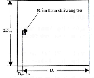
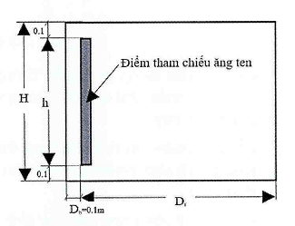
Figure A.1 - Cross section of the domain of compliance of a directional antenna
|
|
a) Cross section of the domain of compliance of the isotropic antenna through the reference point | b) Vertical section of the domain of compliance of the omnidirectional antenna through the reference point |

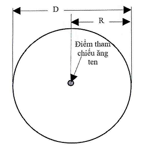
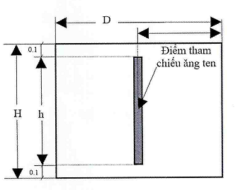
Figure A.2 - Cross section of the domain of compliance of an isotropic antenna in the horizontal direction
A.2. Interpretation
Directional antenna: (Figure A.1)
On the cross section, point F is called the furthest point from the reference point (RP) in the direction of the main beam of the directional antenna.
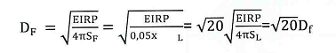
Applying the wave propagation model in free space, with the assumption that point F on the compliant boundary has far-field radiation characteristics, the power density at point F will be:
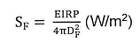
In which:
- EIRP: average equivalent isotropic radiated power of the antenna;
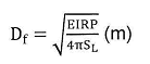
- DF(m): distance from reference point (RP) to point F;
- SF(W/m2): power density at point F.
According to the definition of the compliance boundary, the power density at point F is equal to the exposure limit derived as power density SF = SL, DF = Df. Therefore:
Similarly, point B is the furthest point from the reference point (RP) in the direction of the rear beam of the directional antenna:
![]()
The diameter of the domain of compliance is D = Df + Db (m). Therefore:
![]()
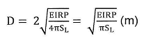
The antenna is omnidirectional in the horizontal direction (Figure A.2).
Choose point A as any point located on the compliance boundary of the isotropic antenna. Similar to above, because the antenna is directional, Df = Db = Da.
Therefore:
A.3 - Domain of compliance size calculation example
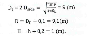
Example 1: Calculating the domain of compliance size for a directional antenna. Assume that a directional antenna has the following parameters:
- Total output power of the transmitters: Pt = 144 w (equivalent to 51.6 dBm);
- Total loss from the transmitter to the antenna L = 6 dB;
- Antenna gain in the main beam direction G = 17.5 dBi;
- Non-occupational exposure limit (derived in terms of equivalent plane wave power density) at antenna transmission frequency SL = 2 w/m2;
- The length of the radiation surface of the antenna h = 0.8 m.
The domain of compliance of this antenna is box-shaped as shown in Figure A.1.
Time-average equivalent isotropic radiant power:
![]()
Equivalent to 63.1 dBm
Domain of compliance size:
Example 2: Calculate the domain of compliance size for a smart directional antenna with the following parameters:
- Total output power of Pt generators = 288 w (equivalent to 54.6 dBm);
- Total loss from the transmitter to the antenna L = 6 dB;
- Antenna gain in the main beam direction G = 24.5 dBi;
- Non-occupational exposure limit (derived in terms of equivalent plane wave power density) at antenna transmission frequency SL = 2 w/m2;
- Radiating surface length of the antenna: h = 0.8 m.
The domain of compliance of this antenna is box-shaped as shown in Figure A.1.
Equivalent isotropic radiant power:
![]()
Average equivalent isotropic radiant power:
![]()
Domain of compliance size:
Appendix B
(Reference)
Determination of the border of the Relevant domain
B.1. Cross section of the Relevant domain
|
|
a) Horizontal section of the Relevant domain of the directional antenna through the reference point | b) Vertical section of the Relevant domain of the directional antenna through the reference point |
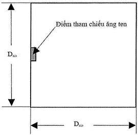
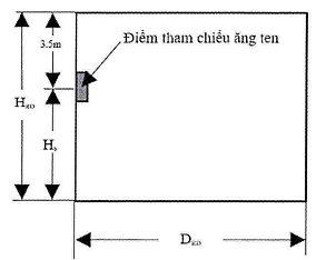
Figure B.1 - Cross-section of the Relevant domain of a directional antenna
|
|
a) Horizontal section of the Relevant domain of the isotropic antenna through the reference point | b) Vertical section of the domain of compliance of the isotropic antenna through the reference point |

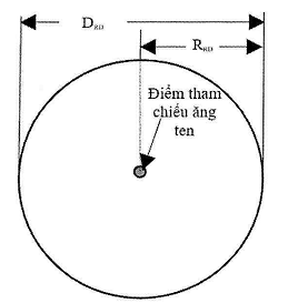
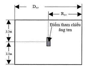
Figure B.2 - Cross-section of the Relevant domain of an isotropic antenna in the horizontal direction
8.2. Interpretation
Directional antenna: (Figure B.1).
On the cross section, point F is called the furthest point from the reference point (RP) in the direction of the main beam of the directional antenna if point F is located on the boundary of the Relevant domain, according to the definition of the Relevant domain, SF = 5 %SL = 0.05 SL.
If the downward antenna has a total elevation angle (Electrical + Mechanical) of a (Degree), then we have:
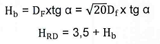
In case Hb (m) < 3.5 (m), calculate in the strictest way Hb (m) = 3.5 (m).
In which:
- EIRP(W): equivalent isotropic radiated power of the antenna;
- DF (m): distance from reference point (RP) to point F;
- Df (m): distance from the antenna reference point to the domain of compliance boundary in front of the antenna;
- HRD: height of Relevant domain (m);
- Hb: height calculated from the reference point of the antenna to the lower edge of the Relevant domain (m);
- a: elevation angle (Electrical + Mechanical) (degrees).
Horizontal omnidirectional antenna (Figure B.2);
Similar to directional antennas,
B.3 - Example of calculating the Relevant domain size
Calculate the Relevant domain size for a directional antenna. Assume a directional base station antenna has the parameters as shown in example 1, Appendix A.3:
- Total output power of the transmitters: Pt = 144 W (equivalent to 51.6 dBm);
- Total loss from the transmitter to the antenna L = 6 dB;
- Antenna gain in the main beam direction G = 17.5 dBi;
- Non-occupational exposure limit (derived as equivalent plane wave power density) at antenna transmission frequency SL = 2 W/m2
Then we can calculate:
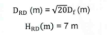
Size of Relevant domain (according to Figure B.1)
![]()
If the antenna elevation angle (Electrical and mechanical in the downward direction) a = 7o (Tg α = 0.1227)
If the antenna elevation angle (Electrical and mechanical in the downward direction) a = 3o (Tg α = 0.0524)
References
[1] ICNIRP Guidelines “Guidelines for limiting exposure to electromagnetic fields (100 KHz to 300 GHz)”, 2020.
[2] QCVN 8: 2010/BTTTT National technical regulation on electromagnetic exposure of public land mobile base stations.
[3] IEC 62232:2017 “Determination of RF field strength, power density and SAR in the vicinity of radio communication base stations for the purpose of evaluating human exposure”.
[4] IEC 62669:2019 “Case studies supporting IEC 62232 - Determination of RF field strength, power density and SAR in the vicinity of radio communication base stations for the purpose of evaluating human exposure”.
[5] ITU-T K.100 (07/2019) - Measurement of radio frequency electromagnetic fields to determine compliance with human exposure limits when a base station is put into service.
[6] ITU-T K.52 (01/2018) - Guidance on complying with limits for human exposure to electromagnetic fields.
[7] ITU-T Series K Supplement 9 (05/2019) - 5G technology and human exposure to RF EMF.
You are not logged in.
This feature is available to Advanced account holders. Please log in to access detailed information on Related documents.
If you do not have an account, please register here!
VIETNAMESE DOCUMENTS
This utility is available to subscribers only. Please log in to a subscriber account to download. Don’t have an account? Register here
This utility is available to subscribers only. Please log in to a subscriber account to download. Don’t have an account? Register here
This utility is available to subscribers only. Please log in to a subscriber account to download. Don’t have an account? Register here
ENGLISH DOCUMENTS
This utility is available to subscribers only. Please log in to a subscriber account to download. Don’t have an account? Register here

