Circular 18/2022/TT-BTTTT National technical regulations on electromagnetic compatibility for coreless audio devices operating on frequencies between 25-2000 MHz
- Summary
- Content
- Status
- Vietnamese
- Related documents
- Diagram
- Download
Please log in to your Advanced Package to view the full text. Do not have an account yet? Register here.
Please log in to use this function
Please log in to use this function
ATTRIBUTE
| Issuing body: | Ministry of Information and Communications | Effective date: | Known Please log in to a subscriber account to use this function. Don’t have an account? Register here |
| Official number: | 18/2022/TT-BTTTT | Signer: | Nguyen Manh Hung |
| Type: | Circular | Expiry date: | Updating |
| Issuing date: | 29/11/2022 | Effect status: | Known Please log in to a subscriber account to use this function. Don’t have an account? Register here |
| Fields: | Information - Communications |
The Effect status of this document is known.This feature is available to Advanced account holders. Please log in to a subscriber account to view Effect status. Don’t have an account? Register here
THE MINISTRY OF INFORMATION AND COMMUNICATIONS No. 18/2022/TT-BTTTT | THE SOCIALIST REPUBLIC OF VIETNAM Independence - Freedom - Happiness Hanoi, November 29, 2022 |
CIRCULAR
On issuance of "National technical regulations on electromagnetic compatibility for coreless audio devices operating on frequencies between 25 Mhz to 2000 MHz"
Pursuant to the Law on Standards and Technical Regulations dated June 29, 2006;
Pursuant to the Telecommunications Law dated November 23, 2009;
Pursuant to the Law on Radio Frequency dated November 23, 2009;
Pursuant to Decree No. 127/2007/ND-CP dated August 1, 2007 of the Government detailing and guiding the implementation of a number of articles of the Law on Standards and Technical Regulations;
Pursuant to Decree No. 78/2018/ND-CP dated May 16, 2018 of the Government amending and supplementing a number of articles of Decree No.127/2007/ND-CP August 1, 2007 of the Government detailing the implementation of a number of articles of the Law on Standards and Technical Regulations;
Pursuant to Decree No. 48/2022/ND-CP dated July 26, 2022 of the Government regulating the functions, tasks, powers and organizational structure of the Ministry of Information and Communications;
At the request of the Director of the Department of Science and Technology,
The Minister of Information and Communications promulgates a Circular regulating national technical regulations on electromagnetic compatibility for coreless audio devices operating on frequencies between 25 Mhz to 2000 MHz.
Article 1. Issued together with this Circular is the National Technical Regulation on electromagnetic compatibility for coreless audio devices operating on frequencies between 25 Mhz to 2000 MHz (QCVN 130:2022/BTTTT).
Article 2. This Circular takes effect from July 1st, 2023.
Article 3. Chief of Office, Director of the Department of Science and Technology, Heads of agencies and units under the Ministry of Information and Communications, Directors of Departments of Information and Communications of provinces and central cities and organizations, relevant individuals are responsible for implementing this Circular./.
| THE MINISTER
Nguyen Manh Hung |

THE SOCIALIST REPUBLIC OF VIETNAM
QCVN 130:2022/BTTTT
NATIONAL TECHNICAL REGULATIONS
ON ELECTROMAGNETIC COMPATIBILITY FOR CORDLESS AUDIO DEVICES OPERATING ON FREQUENCIES BETWEEN 25 MHz TO 2000 MHz
HANOI – 2022
Preface
QCVN 130:2022/BTTTT is built on the basis of ETSI EN 301 489-9 V2.1.1 (2019-04) of the European Telecommunications Standards Institute (ETSI).
QCVN 130:2022/BTTTT was compiled by the Authority of Telecommunications, approved by the Department of Science and Technology, appraised by the Ministry of Science and Technology, and issued by the Ministry of Information and Communications with Circular No. 18/2022/TT- BTTTT date November 29, 2022.
NATIONAL TECHNICAL REGULATIONS
ON ELECTROMAGNETIC COMPATIBILITY FOR CORDLESS AUDIO DEVICES OPERATING ON FREQUENCIES BETWEEN 25 MHz TO 2000 MHz
1. GENERAL RULES
1.1. Scope
This regulation specifies electromagnetic compatibility (EMC) requirements for coreless audio devices operating on frequencies between 25 MHz to 2000 MHz.
This standard specifies EMC tests, test methods, limits and quality criteria for coreless audio devices. Devices can use either analog or digital modulation techniques.
Examples of types of devices are given in Appendix C of this regulation.
Other types of transmitters or receivers used in conjunction with coreless audio devices are not covered by this regulation.
If there are differences (for example, special testing conditions, concepts, terminology) between this regulation and QCVN 18:2022/BTTTT, the provisions of this regulation applied.
Use the environmental classification, emission and immunity requirements in QCVN 18:2022/BTTTT except for special conditions specified in this regulation.
Technical specifications related to antenna ports and emissions from the housing port of coreless audio devices are not within the scope of this regulation, but will be specified in the corresponding product standards and regulations for effective use of the radio frequency spectrum.
HS codes of devices within the scope of this regulation are specified in Appendix A.
The operating frequency of coreless audio devices must comply with regulations on management and use of radio frequencies in Vietnam.
1.2. Applied subjects
This regulation applies to Vietnamese and foreign organizations and individuals that produce and trade devices within the scope of this regulation in the territory of Vietnam.
1.3. References
QCVN 18:2022/BTTTT, National technical regulation on electromagnetic compatibility for radio communication equipment.
QCVN 91:2015/BTTTT, National technical regulation on coreless audio equipment in the frequency range 25 MHz to 2 000 MHz.
ETSI EN 300 422-1 (V2.1.2) (January 2017): "Wireless Microphones; Audio PMSE up to 3 GHz; Part 1: Class A Receivers; Harmonized Standard covering the essential requirements of article 3.2 of Directive 2014/53/ EU".
ETSI EN 300 454-1 (V1.1.2) (August 2000): "Electromagnetic compatibility and Radio spectrum Matters (ERM); Wide band audio links; Part 1: Technical characteristics and test methods".
ETSI EN 300 220-1 (V3.1.1) (February 2017): "Short Range Devices (SRD) operating in the frequency range 25 MHz to 1 000 MHz; Part 1: Technical characteristics and methods of measurement".
1.4. Explanation of words
Use the words specified in QCVN 18:2022/BTTTT and the following words:
1.4.1. Cordless audio devices
The device uses radio waves to transmit sound over short distances. Some typical types of coreless audio devices: coreless microphones, coreless speakers (with radio transceiver), coreless headphones, coreless microphone/speakers.
1.4.2. Companding
An audio signal processing method that involves companding the audio dynamic range before transmission and decompressing the signal at the receiver.
NOTE: This method is used to improve the performance of voice transmission over the radio link.
1.4.3. Integral antenna
The antenna is designed to be connected to the device without using a standard connector and is considered part of the device.
NOTE: The integrated antenna can be mounted inside or outside the device.
1.4.4. Switching range
The largest frequency range within which the receiver and transmitter can operate without reprogramming or frequency realignment.
1.5. Abbreviation
CR | Continuous phenomena applied to Receivers |
CT | Continuous phenomena applied to Transmitters |
e.r.p | effective radiant power |
EMC | ElectroMagnetic Compatibility |
EUT | Equipment Under Test |
LPD | Low Power Device |
PMR | Professional Mobile Radio |
RF | Radio Frequency |
SINAD | Ratio of (Signal + Noise + Distortion) to (Noise + Distortion) |
TR | Transient phenomena applied to Receivers |
TT | Transient phenomena applied to Transmitters |
2. technical regulations
2.1 Emission
Apply section 2.1.1 of Table 1 of QCVN 18:2022/BTTTT, including the applicability of EMC emission measurements to the relevant ports of the radio and/or ancillary equipment.
The specific conditions are specified in Table 1 related to the emission measurement method used in section 2.1 of QCVN 18:2022/BTTTT.
Table 1 - Specific conditions for EMC emission measurements
Reference section of QCVN 18:2022/BTTTT | Special conditions related to equipment, supplement or modification of testing conditions specified in 2.1 of QCVN 18:2022/BTTTT |
2.1.2. Measurement configuration Measurement methods and limits for EMC emissions | The radio equipment must operate on a frequency channel close to the mid-frequency of the switching band declared by the manufacturer. When operating in transmit mode, the transmitter must operate at maximum RF transmit power. |
2.2. Immunity
Apply section 2.2 of QCVN 18:2022/BTTTT, including the possibility of applying EMC immunity measurements to the relevant ports of the radio and/or ancillary equipment.
The specific conditions are specified in Table 2 related to the immunity measurement method used in section 2.2 of QCVN 18:2022/BTTTT.
Table 2 - Specific conditions for EMC immunity tests
Reference section of QCVN 18:2022/BTTTT | Special conditions related to equipment, supplement or modification of testing conditions specified in 2.2 of QCVN 18:2022/BTTTT |
2.2.2. Test configuration
| For transmitter immunity tests, the transmitter must operate at maximum output RF transmit power. Immunity tests shall be performed sequentially for all operating modes of the EUT. |
2.2. Technical conditions
2.3.1. Environmental conditions
The technical requirements in this regulation apply under the operating environment conditions of the EUT declared by the manufacturer. The EUT must comply with all technical requirements of this regulation at all times when operating within the environmental conditions declared by the manufacturer.
2.3.2. Testing conditions
Apply the testing conditions stated in Appendix A of QCVN 18:2022/BTTTT. Other test conditions applicable to wireless audio equipment and ancillary equipment are specified in detail in this regulation.
For emission and immunity tests, test modulation, test arrangement,, etc. are specified in 2.3.2 to 2.3.6 of this regulation.
For EMC tests, portable or portable transmitters shall be mounted on a support made of non-conducting material and at least 0.8 m away from any conductive surface. The EUT and any other equipment required for qualification before, during and after completion of the tests shall be connected in a configuration typical for normal operation.
When the EUT is supplied with a separate antenna, the EUT shall be tested with the antenna installed in a configuration typical for normal operation.
For immunity tests, if the device belongs to the allowable group, it is possible to establish a communication connection from the start of the test and maintain the connection during the test.
Testing conditions include:
- The transmitter shall operate at its normal maximum RF output power level, modulated by a suitable modulating signal (see 2.3.6.1);
- For individual receivers or transmitter receivers operating in simplex mode, the desired input RF signal to be coupled to the receiver shall be modulated by a suitable modulating signal (see 2.3.6.2);
- For duplex transceivers, the desired input RF signal to be coupled to the receiver must be modulated by a suitable modulating signal (see 2.3.6.2). The transmitter shall operate at its normal maximum output RF power level, modulated by a test modulation signal, coupled to the transmitter from the receiver output (repeater mode);
- Digital modulation systems must use a predefined interface to convert between the analog and digital domains (and vice versa).
2.3.3. Arrange test signals
2.3.3.1. General
Apply the regulations in A.2 Appendix A of QCVN 18:2022/BTTTT.
2.3.3.2. Arrange the test signal at the input of the transmitter
Apply the provisions in A.2.2 Appendix A of QCVN 18:2022/BTTTT with the following modifications.
For transmitters designed to operate from an integral or separate microphone (see Figure 2), it shall be permitted to use an acoustic coupling device to insert the normal test modulation signal (see Figure 3). Audio coupling devices may be provided by the manufacturer.
For devices that can use many types of recording heads, the manufacturer must declare the type of recording head used in the system, for example, the type of electric field induction recording head (dynamic), the electrostatic recording head (condenser), electrostatic capacitor (electret) recording head. The transmitter is tested at the input level most sensitive to the test receiver.
For equipment not designed to use an integrated microphone or a separate microphone, the signal is applied electrically to the most sensitive input terminal (see Figure 1) using the longest cable normally recommended by the manufacturer supplied with devices.
The modulation signal used for the tests is a 1 kHz sinusoidal monophonic signal at the level declared by the manufacturer until 100 % audio modulation is achieved.
The manufacturer may provide a suitable receiver that can be used to establish a communications connection. In this case a suitable attenuator can be used in the attached receiver input, see Appendix B for details.
In the case of a system using digital audio input and output, the test signal must be passed through a suitable test converter to convert the analog signal to a digital signal and vice versa. The manufacturer shall provide detailed information on the interface and test adapter used for the test.
2.3.3.3. Arrange testing at the output of the generator
Apply the regulations in A.2.3 Appendix A of QCVN 18:2022/BTTTT.
2.3.3.4. Test arrangement at the receiver input
Apply the regulations in A.2.4 Appendix A of QCVN 18:2022/BTTTT with the following adjustments.
The RF wanted signal input to the receiver is modulated by a suitable signal corresponding to 100 % audio modulation (maximum channel load). If it is not possible to provide a modulated RF signal to the receiver, the test may be performed using an unmodulated input RF wanted signal.
The manufacturer must declare the level and method of generating the input RF wanted signal. The selected level must be set to a value 60 dB greater than the receiver's threshold sensitivity. Other similar wireless microphone systems may specify different levels corresponding to the application. This level must be recorded in the test report.
The manufacturer must provide a suitable transmitter that can be used to establish a communications connection. In this case, a suitable attenuator can be used in the EUT if necessary.
![]()
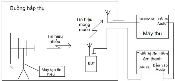
Figure 1 - Test configuration for integrated antenna; Generator operation - input electrical signal

Figure 2 - Test configuration for integrated antenna; transmitter operation - input audio signal
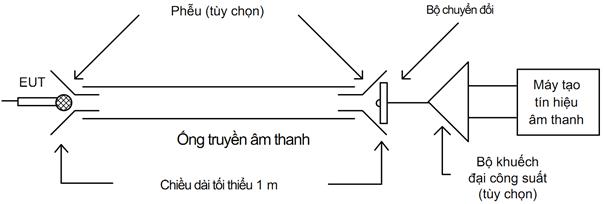
Figure 3 - Example of an audio coupler

NOTE: The RF signal generator can be accompanied by a transmitter located inside the measurement chamber if necessary.
Figure 4 - Test configuration for integrated antenna; receiver operation
2.3.3.5. Arrange testing at the output of the receiver
Apply the regulations in A.2.5 Appendix A of QCVN 18:2022/BTTTT with the following modifications.
The receiver's output audio frequency signal can be inserted into the SINAD measurement system outside the measurement chamber. The characteristics of the SINAD system must ensure that the -3 dB upper frequency of the detector is greater than 16 kHz and that the electrical flatness error between 40 Hz and 16 kHz does not exceed ±2 dB. The signal coupling devices used for testing must be included in the test report.
In the case of a system using digital audio output, the manufacturer must specify a suitable test converter to convert the digital signal to an analog signal. The manufacturer shall provide detailed information on the interface and test adapter used for the test. Interfaces must ensure that they meet the above technical requirements.
2.3.3.6. Arrange for testing the receiver and transmitter together (as one system)
Apply the regulations in A.2.5 Appendix A of QCVN 18:2022/BTTTT.
In the case of digital modulation systems, the manufacturer must specify a suitable test converter to convert the analog signal to a digital signal and vice versa. The above determination shall be included in the test report.
2.3.4. Exclusion band
2.3.4.1. General
Apply A.3 Appendix A QCVN 18:2022/BTTTT.
2.3.4.2. Exclusion band for the receiver and transceiver receivers
The exclusion band for the receiver and transceiver receivers is the frequency band determined by the switching range declared by the manufacturer extended as follows:
1) Class 1 and Class 2 equipment (as defined in 2.5)
- The lower bound frequency of the exclusion band is the lower bound frequency of the switching band minus 5% of the center frequency value of the switching band.
- The upper bound frequency of the exclusion band is the upper bound frequency of the switching band plus 5% of the value of the center frequency of the switching band.
2) Class 3 equipment (as defined in 2.5)
- The lower bound frequency of the exclusion band is the lower bound frequency of the switching band minus 5% of the center frequency value of the switching band or minus 10 MHz, choose the appropriate value to get the lowest frequency.
- The upper limit frequency of the exclusion band is the upper limit frequency of the switching band plus 5% of the center frequency value of the switching band or plus 10 MHz, choose the appropriate value to get the highest frequency.
The manufacturer must declare the device type in the documentation accompanying the product and must provide information about the device type to the testing laboratory.
2.3.4.3. Exclusion band for transmitter
The lower bound frequency of the exclusion band is the lower bound frequency of the switching band minus 5 % of the value of the center frequency of the switching band.
The upper bound frequency of the exclusion band is the upper bound frequency of the switching band plus 5 % of the value of the center frequency of the switching band.
2.3.5. Narrowband response of the receiver
The responses on the receiver, receiving part of the transceiver (duplex) that occur during immunity testing at discrete frequencies are narrowband responses (spurious responses) determined by the following method.
If during testing, the RF immunity test signal (see 2.2.3 and 2.2.6 of QCVN 18:2022/BTTTT) causes the receiver to fail to comply with the specified criteria (see Appendix C), This noncompliance should be determined in terms of the narrowband response or in terms of the broadband phenomenon. Therefore, the frequency of the test signal is increased by two times the nominal 6 dB bandwidth of the IF filter immediately preceding the receiver modulator, or, if appropriate, the equipment bandwidth for operation determined by the manufacturer. The test is repeated with the test signal frequency reduced by the same amount.
If the receiver complies with the specified criteria in one or both cases of frequency deviation, the response is considered to be a narrowband response.
If the receiver still does not comply with the specified criteria in one or both cases of frequency deviation, this may in fact be a deviation made to the frequency of the unwanted signal corresponding to a response of another narrow band. In this case the above procedure is repeated increasing or decreasing the test signal frequency to twice the bandwidth or half the reference bandwidth above.
If the receiver still does not comply with the specified criteria in one or both cases of frequency deviation, the phenomenon is considered wideband and the device therefore fails the EMC test.
For immunity testing, the narrowband response must be ignored.
The identification criteria for the narrowband response of the EUT is that the observed SINAD level attenuation at the audio output is below the relevant category limit specified in Table 4, see 2.5.2.
The nominal frequency offset used for identification of narrowband responses shall be twice the bandwidth of the receiver IF filter immediately preceding the demodulator, as declared by the manufacturer, for the first part of the procedure recognition and 2.5 times the receiver bandwidth for the second part.
For digital systems, the narrowband response must be limited to less than 3 times the system's declared bandwidth (B). See ETSI EN 300 422-1, ETSI EN 300 454-1 QCVN 91:2015/BTTTT.
2.3.6. Normal test modulation
2.3.6.1. Generator
The transmitter is modulated by a 1 000 Hz sinusoidal audio signal, supplied through a suitable audio coupler or shielded transmission cable (e.g. coaxial cable). The level of this audio signal shall be adjusted to 100 % audio modulation (maximum channel load) of the desired signal.
For digital modulation systems, the manufacturer shall indicate the method and parameters of modulation and provide suitable measurement conversion equipment to allow analog testing of 100 % audio modulation level.
2.3.6.2. Recorder
The receiver's input RF wanted signal shall be established at the receiver's operating frequency within the designed operating frequency range and modulated by a 1 000 Hz sinusoidal audio signal, is supplied via a measurement antenna located inside the measurement room (for receivers with integrated antennas) or shielded transmission cables such as coaxial cables (for receivers without integrated antennas). The level of the modulating signal shall be adjusted to 100 % audio modulation (maximum channel load) of the receiver's input RF wanted signal.
For digital modulation systems, the manufacturer shall indicate the method and parameters of modulation and provide suitable measurement conversion equipment to allow analog testing of 100 % audio modulation level.
2.4. Auxiliary equipment
Apply Appendix B of QCVN 18:2022/BTTTT.
2.5. Quality criteria
2.5.1. Introduction
2.5.1.1. General
The group of coreless microphone devices is divided into 3 types, each with its own set of quality criteria:
- Type 1 devices include coreless microphone equipment and accompanying ancillary equipment used for professional applications;
- Type 2 devices include coreless microphone devices, coreless audio devices, in-ear monitoring devices and accompanying auxiliary devices for home entertainment;
- Type 3 devices include coreless microphone devices, coreless audio devices, coreless headset devices and accompanying auxiliary devices for general purposes (coreless microphones that satisfy technical and exploited according to regulations, regardless of application or purpose of use).
The user manual must contain information about the intended use of the product, specifically stated as “Professional applications” (Type 1 devices), “Home entertainment” (Type 2 devices) or “General Purpose” (Type 3 devices).
The establishment of a communication connection at the start of the test, the maintenance of the connection and the evaluation of the recovered signal (e.g. output audio signal) are used as quality criteria to evaluate the essential function of the device during and after testing.
Quality criteria A, B and C stated in Table 3 must be used in the following cases:
- Quality criterion A applies to immunity measurements for continuous phenomena;
- Quality criterion B applies to interruption immunity measurements;
- Quality criterion C applies to measurements of power interruptions, voltage drops exceeding a specified period of time.
2.5.1.2. General quality criteria
Equipment must meet the quality criteria specified in Table 3 and specific regulations on specific quality criteria respectively in sections 2.5.2.1, 2.5.2.2 and 2.5.2.3.
Table 1 - General quality criteria
Criteria | During testing | After trying the test |
A | Works as expected Performance degradation (see NOTE 1) No loss of functionality | Works as expected No performance degradation (see NOTE 2) No loss of functionality |
B | Loss of one or more functions | Works as expected No performance degradation (see NOTE 2) Lost functionality can be restored on its own |
C | Loss of one or more functions | Works as expected No performance degradation (see NOTE 2) The operator can restore lost functionality |
NOTE 1: Performance degradation during testing is understood as a reduction to a level not lower than the minimum performance level declared by the manufacturer for the intended use of the equipment. In some cases the minimum performance level may be replaced by an allowable performance degradation level. If the manufacturer does not state the allowable level of performance degradation, this level can be taken from the product description and product literature (including leaflets and advertisements) and the level that the user can reasonable expectations from the product if used as intended. NOTE 2: No loss of performance after testing is understood as no loss of performance below the minimum performance level announced by the manufacturer for the intended use of the device. In some cases the minimum performance level may be replaced by an allowable performance degradation level. After testing no changes to the actual operating data or stored user data are allowed. If the manufacturer does not declare the maximum feature levelminimalor the allowable level of performance degradation, this level can be obtained from the product description and product literature (including leaflets and advertising) and the level that users can reasonably expect from the product. product if used as intended. | ||
2.5.2. Quality requirements
2.5.2.1. Quality criteria for equipment that can provide continuous information connection
a) General
The establishment of a communication connection at the start of the test, the maintenance of the connection and the evaluation of the recovered signal, e.g. the audio signal, are used as quality criteria to ensure functionalities. Transmitter and/or receiver settings are evaluated during and after the test.
Equipment must meet the minimum quality criteria specified for the type of devices stated in sections 2.5.1.1 and 2.5.1.2.
b) Quality criteria for continuity phenomena applicable to transmitter (CT) and receiver (CR)
The following performance criteria for continuity apply to the transmitter (CT) and receiver (CR) or receiver section of simplex or duplex transceivers (CR) allowing the establishment of a connection providing information continuously:
- Before testing, it must be ensured that the EUT, when coupled to the measuring equipment and not subject to EMC influences, is capable of producing a SINAD pattern at least 3 dB higher than the limits stated in Table 4;
- During each individual exposure in the test series, it shall be ensured that the communication connection is maintained by appropriate means provided by the manufacturer;
- At the end of the test, the EUT must operate as intended, without loss of control functions or user data as declared by the manufacturer, and the communication connection must be maintained at all times throughout the test.
During and after testing, the output audio signal must be monitored and evaluated. During the test, SINAD's output audio signal is not degraded to a level below the relevant limit specified in Table 4. After testing SINAD must recover to the level recorded before the test and the level must not be lower than the relevant limit specified in Table 4.
Table 4 - Continuous phenomenon, minimum quality criteria
Type of device | Minimum quality criteria | Uses |
Type 1 | 30 dB SINAD | Professional applications |
Type 2 | 20 dB SINAD | Family entertainment |
Type 3 | 6 dB SINAD | General purpose |
In cases where the EUT is only a transmitter and operates in standby mode, the tests must be repeated when the EUT operates in standby mode to ensure that no unexpected signal generation occurs.
In case the EUT is a transceiver, during testing there must be no situation where the transmitter does not operate as expected.
c) Quality criteria for surge phenomena apply to transmitter (TT) and receiver (TR)
The following quality criteria for surge phenomena apply to the transmitter (TT) and receiver (TR) or receiver section of simplex or duplex transceivers (TR) allowing the establishment of a connection providing information continuously:
- Before testing, it must be ensured that the EUT, when coupled to the measuring equipment and not subject to EMC influences, is capable of producing a SINAD pattern at least 3 dB higher than the limits stated in Table 4;
- At the end of each exposure in the test series, the EUT shall operate without the user noticing any loss of communication;
- At the conclusion of all tests, including the individual exposure sequence, the EUT shall operate as intended, without loss of control functions or user data as declared by the manufacturer, and with the communication must be maintained at all times throughout the test.
After testing, the output audio signal must be monitored and evaluated. After testing, SINAD must recover to the level recorded before the test or at least to a level not lower than the relevant limit specified in Table 4.
In cases the EUT is only a transmitter and operates in standby mode, the tests must be repeated when the EUT operates in standby mode to ensure that no unexpected signal generation occurs.
In case the EUT is a transceiver, during testing, there must be no situation where the transmitter does not operate as expected.
2.5.2.2. Quality criteria for devices that do not provide continuous communication connections
For devices that do not provide continuous communication connections, the manufacturer shall declare the device specification for acceptable levels of performance or deterioration during and/or after testing and inform in inclusion in the test report. This quality specification must be included in the product documentation and description. The relevant specifications in section 2.4.3 must also be taken into account.
The quality criteria specified by the manufacturer must provide the same level of immunity protection as stated in section 2.5.1.
For continuity immunity tests, the device does not allow the establishment of a continuous communication connection and the accessory is intended to be tested on an individual device basis, the following quality criteria shall be met: :
- Quality criteria A for class 1 devices;
- Quality criteria C for class 2 and class 3 devices as described in Table 3.
For surge immunity tests, the device that does not allow the establishment of a continuous communication connection and the accessory intended to be tested independently shall meet performance criterion B as described in Table 3, except for voltage drop and voltage interruption immunity tests (see section 2.2.8 of QCVN 18:2022/BTTTT), in which it must be clearly stated that there is no need to maintain a communication connection to not apply Quality criteria C specified in Table 3.
2.5.2.3. Quality criteria for auxiliary devices be independently tested
If the device is independently tested, the manufacturer shall declare the device specification for the acceptable level of performance or performance degradation during and/or after the immunity test and to include into the test report. This feature specification must be included in the product documentation and description. The relevant specifications in section 2.4.3 must also be taken into account.
The quality criteria specified by the manufacturer must provide the same level of immunity protection as stated in section 2.5.1.
3. REGULATIONS ON MANAGEMENT
3.1. Coreless audio devices within the scope of regulation specified in 1.1 must comply with the provisions of this Regulation.
3.2. Measuring devices and equipment: Comply with current regulations.
4. RESPONSIBILITIES OF ORGANIZATIONS AND INDIVIDUALS
4.1. Relevant organizations and individuals are responsible for implementing regulations on declaration of conformity of coreless audio devices operating on frequencies between 25 MHz to 2,000 MHz and are subject to inspection by state management agencies according to current regulations.
5. IMPLEMENTATINg ORGANIZATION
5.1. The Authority of Telecommunications and the Departments of Information and Communications are responsible for organizing guidance and implementing the management of coreless audio devices operating on frequencies between 25 MHz to 2,000 MHz according to this Regulation.
5.2. In case the regulations stated in this Regulation are changed, supplemented or replaced, the provisions in the new document shall comply.
5.3. During the implementation of this Regulation, if any problems or difficulties arise, relevant organizations and individuals should report in writing to the Ministry of Information and Communications (Department of Science and Technology) for guidance and solutions./.
Appendix A
(Regulations)
HS code of coreless audio devices operating on frequencies between 25 MHz to 2000 MHz
TT | Name of products and goods according to QCVN | HS code | Description of products, goods |
1 | Coreless audio devices operating on frequencies between 25 MHz to 2000 MHz | 8518.10.11 8518.10.19 8518.10.90 | The coreless microphone has an operating frequency range of 25 MHz to 2000 MHz |
8518.21.10 8518.21.90 8518.22.10 8518.22.90 8518.29.20 8518.29.90 | The coreless speaker has an operating frequency range of 25 MHz to 2000 MHz | ||
8518.30.10 8518.30.20 | The coreless headset has an operating frequency range of 25 MHz to 2000 MHz | ||
8518.30.51 8518.30.59 8518.30.90 | The coreless combination microphone/speaker has an operating frequency range of 25 MHz to 2000 MHz |
Appendix B
(Regulations)
Sound stimulation of coreless microphones, conditions for test setup and configuration
B.1. General
This annex specifies methods for exciting the EUT when performing EMC measurements referred to in this regulation, with recognition of the somewhat unusual performance of coreless microphones when compared with general radio devices.
Coreless microphones vary greatly in sensitivity and sound directionality of the receiver.
When testing coreless microphones, always remember that many products use different compression and decompression techniques.
When having difficulty or uncertainty about the characteristics of the sample, it is necessary to discuss with the manufacturer.
B.2. Sound stimulation
Part of the EMC test series described in this regulation requires providing an acoustic stimulus signal to the microphone transducer. This can be done in at least two ways:
1) By electro-acoustic resonance device (to avoid distortion of the calibration field, this device must be non-metallic and placed outside the calibration area); or
2) By sound transmission tube (rigid or flexible but must have a solid sound wall, made of non-conducting material and have a constant inner diameter throughout the tube length).
The driving transducer must be wide enough and of sufficient gain, capable of transferring the sound pressure at the microphone to a level that fully excites the EUT's modulator. However, overload must be avoided.
The guide transducer must be placed far enough away from the EUT's microphone (due to the typically moving magnetic coil type), to avoid magnetic coupling between the transducers and to avoid distortion due to the test electromagnetic field.
Funnels or suitable devices can be used to coordinate with the guide transducer and with the microphone transducer of the EUT. Mounting devices must be firmly fixed throughout the measurement process.
When the transducer is coupled to the EUT using an audio tube, the audio tube shall avoid or minimize bending. Any bends in the pipe must ensure that the bend diameter is larger than the inside diameter of the pipe.
Standing waves in the pipe must be overcome by anti-vibration cotton padding spaced 150 mm apart along the pipe length. The guide adapter should be located inside the measurement room to minimize pipe length.
NOTE: This method has been successfully tested using a 1m long pipe. The pipe used is a 12.5 mm reinforced plastic water pipe. The guide transducer is a 75 mm car radio speaker with a large ferrite magnet, capable of peak-to-peak cone displacement greater than 10 mm. The lead is connected to the tube using a household-use plastic funnel.
Appendix C
(Reference)
Examples of coreless audio devices covered by the regulation
C.1. Coreless microphone devices
Coreless microphone devices operate with a continuous output RF signal and typically operate continuously for a few hours. Signal modulation can be either analog or digital modulation. The transmitter typically operates at a maximum RF output power of 50 mW. Wireless microphone devices are used for professional purposes in theaters, performances, promotions, etc. and can be distinguished from voice information devices (eg PMR) by their following operating characteristics:
- Wider audio bandwidth;
- Higher audio signal-to-noise ratio;
- Distortion of lower audio frequencies.
Disabled assistive devices, tour guide systems, in-ear monitoring devices, and similar RF devices operate in a similar way to wireless microphones, but with variations in bandwidth and technology. The output RF power is reduced and there may be deterioration in the quality of speech or voice signal transmission.
C.2. Other coreless audio devices
Coreless audio devices include coreless headphones and speakers. Transmitters can be installed in buildings, on vehicles or on people. The term coreless is also used to describe infrared or non-RF coreless connections, but in this standard, it is only used for RF radio-operated systems. Analog or digital stereo devices can be designed for required channel bandwidths of 300 kHz, however multi-channel devices such as surround sound systems may require higher bandwidths of 600 kHz or 1 200 kHz as described in QCVN 91:2015/BTTTT.
With this way of batching operations, the following applications can be identified (the list is not limited) as follows:
- Coreless speakers: Coreless speakers are used in home environments and are used to connect wirelessly from audio systems or TVs and similar systems;
- Coreless Headphones: Coreless headphones are used in home devices and are used to connect wirelessly from audio systems or TVs and similar systems;
- In-ear monitors: In-ear monitors are used by people on stage and in the studio to receive personal performance signals transmitted back (monitoring). This is to help adjust the performer's voice or mix multiple signal sources. Usually this device is a 2-channel or stereo audio device.
References
[1] ETSI EN 301 489-9 V2.1.1 (2019-04): ElectroMagnetic Compatibility (EMC) standard for radio equipment and services; Part 9: Specific conditions for wireless microphones, similar Radio Frequency (RF) audio link equipment, cordless audio and in-ear monitoring devices; Harmonized Standard covering the essential requirements of article 3.1(b) of Directive 2014/53/EU;
You are not logged in.
This feature is available to Advanced account holders. Please log in to access detailed information on Related documents.
If you do not have an account, please register here!
VIETNAMESE DOCUMENTS
This utility is available to subscribers only. Please log in to a subscriber account to download. Don’t have an account? Register here
This utility is available to subscribers only. Please log in to a subscriber account to download. Don’t have an account? Register here
This utility is available to subscribers only. Please log in to a subscriber account to download. Don’t have an account? Register here
ENGLISH DOCUMENTS
This utility is available to subscribers only. Please log in to a subscriber account to download. Don’t have an account? Register here

