Circular No. 29/2017/TT-BTTTT dated November 7th, 2017 of the Ministry of Information and Communications on promulgating the "National Technical regulation on Mobile Satellite Earth Station (MES) operating in the KU band"
- Summary
- Content
- Status
- Vietnamese
- Related documents
- Diagram
- Download
Please log in to your Advanced Package to view the full text. Do not have an account yet? Register here.
Please log in to use this function
Please log in to use this function
ATTRIBUTE
| Issuing body: | Ministry of Information and Communications | Effective date: | Known Please log in to a subscriber account to use this function. Don’t have an account? Register here |
| Official number: | 29/2017/TT-BTTTT | Signer: | Truong Minh Tuan |
| Type: | Circular | Expiry date: | Updating |
| Issuing date: | 07/11/2017 | Effect status: | Known Please log in to a subscriber account to use this function. Don’t have an account? Register here |
| Fields: | Information - Communications |
The Effect status of this document is known.This feature is available to Advanced account holders. Please log in to a subscriber account to view Effect status. Don’t have an account? Register here
THE MINISTRY OF INFORMATION AND COMMUNICATIONS
Circular No. 29/2017/TT-BTTTT dated November 7th, 2017 of the Ministry of Information and Communications on promulgating the "National Technical regulation on Mobile Satellite Earth Station (MES) operating in the KU band"
Pursuant to the Law on Technical Standards and Regulations dated June 29th, 2006;
Pursuant to the Law on Telecommunications dated November 23rd, 2009;
Pursuant to the Law on Radio Frequency dated November 23rd, 2009;
Pursuant to Decree No. 127/2007/ND-CP dated August 1st, 2007 of the Government on detailing and guiding the implementation of a number of articles of the Law on Technical Standards and Regulations;
Based on Decree No. 17/2017/ND-CP dated February 17th, 2017 of the Government on defining the functions, tasks, powers and organizational structure of the Ministry of Information and Communications;
At the request of the Director of Science and Technology Department,
Minister of Information and Communications hereby issues the Circular on prescribing national technical regulation on mobile satellite earth station operating in the Ku band.
Article 1.Issue together with this Circular National Technical Regulation on mobile satellite earth station operating in the Ku band (QCVN 116:2017/BTTTT).
Article 2.This Circular takes effect from July 1st, 2018.
Article 3.Chief of the staff, Director of Science and Technology, heads of the agencies and units under the Ministry of Information and Communications, Directors of the provincial/municipal Information and Communications, and concerned organizations and individuals shall implement this Circular.
The Minister
Truong Minh Tuan
Preface
QCVN 116:2017/BTTTT is established based on EN 301 427 V2.2.1 (2016-06) of the European Telecommunications Standards Institute (ETSI).
QCVN 116:2017/BTTTT is compiled by the Research Institute of Posts and Telecommunications (RIPT), appraised and submitted for approval by Department of Science and Technology, and issued by Ministry of Information and Communications (MIC) attached with Circular No. 29/2017/TT-BTTTT dated November 7th, 2017.
NATIONAL TECHNICAL REGULATION ON MOBILE SATELLITE EARTH STATION (MES) OPERATING IN THE KU BAND
1 GENERAL PROVISIONS
1.1 Scope of adjustment
This regulation specifies the radio spectrum requirements for mobile satellite earth station (mobile earth station) (MES), except for air mobile earth stations operating in the Ku band.
- This regulation applies to MES operating in the frequency bands of fixed-satellite service:
• 10.70 GHz to 11.70 GHz (space-to-earth);
• 12.50 GHz to 12.75 GHz (space-to-earth);
• 14.00 GHz to 14.25 GHz (earth-to-space).
- MES can be:
Land mobile earth station (LMES), and/or
Maritime mobile earth station (MMES) does not provide security and rescue functions as required by the International Maritime Organization (IMO).
- LMES can be mounted on car or portable devices.
- MMES is a device installed on board.
- MES may include some modules that have a keyboard for users.
- MES uses linear polarization.
- MES operates through 3° spacing geostationary satellite operating in the same band and areas.
- Antenna of the MES can be isotopic or directional.
- MES is acting as part of a satellite network used for the distribution and/or exchange of information among users.
- MES is controlled and monitored by network control feature (NCF).
1.2 Subjects of application
This technical regulation applies to Vietnamese and foreign agencies, organizations and individuals engaged in production and business activities and exploitation of equipment under the governing scope of this Regulation in the territory of Vietnam.
1.3 Normative documents
CISPR 16-1: "Specification for radio disturbance and immunity measuring apparatus and methods; Part 1: Radio disturbance and immunity measuring apparatus".
1.4 Interpretation
1.4.1 Carrier-off state
MES is in this state when MES is allowed by the NCF to transmit but does not signal or isn’t allowed to transmit.
1.4.2 Carrier-on status
MES in this state when MES is allowed by NCF to transmit and transmit a signal.
1.4.3 Control channel (CC)
One or more channels through which MES receives the control signal from NCF.
1.4.4 Externally Mounted Equipment (EME)
EME includes modules of the installed equipment (IE) intended to be mounted outside the car as announced by the manufacturer.
1.4.5 Installable Equipment (IE)
Equipment used to equip to car.
NOTE: IE can include one or more modules connected together.
1.4.6 Internally Mounted Equipment (IME)
IE’S modules are not declared by the manufacturer in the same way that EME is defined as IME
1.4.7 Mobile Earth station (MES)
An earth station under the Mobile service through satellite is used while moving or stopping at unspecified points.
1.4.8 Nominated bandwidth
Transmission bandwidth of radio frequency MES is determined by manufacturer. Nominated bandwidth is big enough to contain the entire transmission spectrum component with the level greater than specified unintended emission limits and take into consideration the stability of the transmission carrier-on frequency.
1.4.9 Portable Equipment (PE)
A complete, desktop or portable device. An PE generally consists of a single block or several blocks connected together.
1.4.10 Unintended emissions
The emissions are out of nominated bandwidth
1.4.11 E-plane
For a linearly polarized antenna, it’s a plane containing electric field vectors and direction of maximum radiation. The electric field or plane E determine the polarization or direction of the radio wave. For a vertically polarized antenna, plane E generally coincides with the vertical planes. For a horizontally polarized antenna, plane E often coincides with the horizontal plane.
1.5 Abbreviation
CC Control Channel
CMF Control and Monitoring Functions
EIRP Equivalent Isotropically Radiated Power
EME Externally Mounted Equipment
EUT Equipment Under Test
IE Installable Equipment
IME Internally Mounted Equipment
LMES Land Mobile Earth station
MES Mobile Earth Station
MMES Maritime Mobile Earth Station
NCF Network Control Facility
ITU International Telecommunication Union
PE Portable Equipment
RF Radio Frequency
rms root mean square
R&TTE Radio and Telecommunications Terminal Equipment
STE Special Test Equipment
2 TECHNICAL REGULATIONS
2.1 Environmental conditions
The technical requirements of this regulation is applied in the operating environment condition of the equipment announced/declared by the manufacturer. This equipment must comply with all technical requirements of this regulation when operating within the boundary limit of the declared operating environment condition.
The operating environment condition of the equipment shall be in the range of humidity, temperature and supply source.
2.2 Technical requirements
2.2.1 Unintended out-of-band emission
2.2.1.1 Purpose
Protect land and satellite services from emissions due to MES out of band from 14.00 GHz to 14.25 GHz.
2.2.1.2 Requirement
Unintended emissions in the measurement band and in all directions from MES out of band from 14.00 GHz to 14.25 GHz shall be below the following limits:
1. Unintended emissions in frequency range from 30 MHz to 000 MHz should not exceed the limits in Table 1a for LMES and Table 1b for MMES.
Table 1a – Unintended emission limit for LMES at frequencies from 30 MHz to 1000 MHz at measuring distance of 10m with band of 120 kHz
Frequency (MHz) Near-top limit (dBμV/m)
30 - 230 30
230 - 1 000 37
Table 1b – Unintended emission limit for MMES at frequencies from 30 MHz to 1000 MHz at a measuring distance of 10m with band of 120 kHz
Frequency (MHz) Near-top limit (dBµV/m)
30-156 30
156-165 14 (see note)
165-230 30
230 - 1 000 37
NOTE: For the band from 156 MHz to 165 MHz, the applicable bandwidth is 9 kHz.
Transition frequencies are subject to a lower limit.
2. Equivalent Isotropically Radiated Power (EIRP) of the unintended emission for frequencies above 1000 MHz in the measurement band and in all directions shall not exceed the limits specified in Table 2.
Table 2 - Unintended emission limit at frequencies over 1000 MHz and out of band from 14.00 GHz to 14.25 GHz
Frequency (MHz) Carrier-on Carrier-off
EIRP limit (dBpW) Measurement band (kHz) EIRP limit (dBµW) Measurement band (kHz)
1 000 - 1 525 49 100 48 100
1 525 - 1 559 49 100 17 3
1 559 - 3 400 49 100 48 100
3 400 - 10 700 55 100 48 100
10 700 - 21 200 61 100 54 100
21 200 - 40 000 67 100 60 100
The transition frequencies are subject to a lower limit.
2.2.1.3 Testing
In accordance with 3.1.
2.2.2 Unintended out-of-band emission
2.2.2.1 Purpose
Protect the services mainly operating in the band from 14.00 GHz to 14.25 GHz.
2.2.2.2 Requirement
Requirement 1: Carrier-on state
EIRP spectral density of unintended emission shall be less or equal to 4 -10 log N dBW/100 kHz in band from 14.00 GHz to 14.25 GHz and out of nominated band.
N is the highest number of MESs simultaneously emitted in the same frequency. The number of MESs simultaneously emitted shall not exceed 0.01% of the time. Value N and operating conditions of the measuring system are declared by the manufacturer.
Requirement 2: Carrier-off state
EIRP spectral density of any emission in frequency band from 14.00 GHz to 14.25 GHz shall be less or equal to -21 dBW/100 kHz.
2.2.2.3 Testing
In accordance with 3.2.
2.2.3 EIRP emission density in nominated band
2.2.3.1 Purpose
Protect other satellite systems using the same frequency band.
2.2.3.2 Requirement
The directional antenna with largest EIRP in any 40 kHz range from any polarized MES in the direction of Ф degree from the main lobe axis of the antenna shall not exceed the limits in geostationary satellite orbit with spacing of 3°:
33 - 25 Ig (Ф + δФ) -10 lg(K) dBW/40 kHz with 2.5° ≤ Ф + δФ ≤ 7,0°;
12-10 lg(K) dBW/40 kHz with 7.0° < Ф < δФ ≤ 9,2°;
36 - 25 Ig (Ф + δФ) -10 lg(K) dBW/40 kHz with 9.2° < Ф < δФ ≤ 48°;
- 6 -10 lg(K) dBW/40 kHz with 48° < Ф < δФ ≤ 180°.
Where Ф is the angle between main lobe axis and direction of projection (the measuring unit is degree). The value of δФ or:
a) Effective value of the antenna, or
b) Twice as high as effective value of the antenna, whichever is greater.
K is t dependence the power density between e composting system Load and MES measurements in 40 kHz bandwidth.
The value of K for all specifications and operating conditions declared by the manufacturer shall be recorded in the testing result report.
These limits apply to the latitude and geostationary orbit declared by the manufacturer.
For unidirectional antennas, EIRP with maximally 40 kHz in any direction shall not exceed:
- 6 - 10 log (K) dBW/40 kHz;
Where: K is defined as above.
2.2.3.3 Testing
In accordance with Article 3.3.
2.2.4 Control and monitoring functions (CMF)
The following minimum control and monitoring functions shall be used for MES to minimize the possibility that MES can form unintended transmissions and cause harmful interference to other systems.
MES is limited and shall apply carrier-off state when transmitting any error state.
2.2.4.1 Processor monitoring
1. Purpose
To ensure that MES can prohibit transmission in case of failure of processing.
2. Requirement
MES must combine the function of microprocessor monitoring with its processor related to management of capacity and control and monitoring functions.
The processor monitoring function must detect hardware and software failures of the processor.
In about 1 second after an error, MES switches to carrier-off state until the processor monitoring function determines all errors are fixed.
3. Testing
In accordance with Article 3.4.
2.2.4.2 Transmission subsystem monitoring
1. Purpose
In order to ensure the exact operation of transmission frequency subsystem and limit the transmission if the subsystem is down.
2. Requirement
MES will monitor the operation of its transmission frequency subsystems.
No more than 5 seconds after failure in transmission frequency subsystem, MES changes to carrier-off state until the transmission subsystem monitoring function identifies that all such errors have been resolved.
3. Testing
In accordance with Article 3.4.
2.2.4.3 Power off
1. Purpose
To ensure that MES reaches controlled non-transmission state after switch off the power of the equipment, the operator shall shut down the source when this function is in effect.
2. Requirement
When performing the power-off, MES is maintained in a carrier-off state.
3. Testing
In accordance with Article 3.4.
2.2.4.4 Receiver control (CC)
1. Purpose
To ensure that MES can’t transmit unless MES correctly receive the control channel message from NCF.
2. Requirement
a) Without proper reception of CC messages from NCF, MES will be maintained in carrier-off state.
b) MES must switch to carrier-free mode immediately after a period of no more than 30 seconds without accurately collecting CC messages from the NCF.
3. Testing
In accordance with Article 3.4.
2.2.4.5 Network control commands
1. Purpose
These requirements ensure that MES is capable of:
a) Maintaining unique identification in network and transmit it when receiving a suitable request;
b) Receive commands from NCF through CC and follow these commands.
2. Requirement
MES shall store its unique identifier in the network.
MES can receive through its CC for notice (sent to MES) from NCF and contain:
- Transmission allowing command;
- Transmission prohibiting command;
- Identification requirement.
Upon receipt of the transmission allowing command, MES is allowed to transmission.
After power on, MES will remain in the carrier-off state until it receives the transmission allowing command. For systems without expected transmission allowing command, after power on, MES can only transmit initialization clusters (see 22.5.6).
Upon receiving transmission prohibiting command, within 1 second, MES switches to carrier-off state until the transmission prohibiting command is replaced by next transmission allowing command.
MES must be capable of transmitting its identifier when receiving an identification request.
3. Testing
In accordance with Article 3.4.
2.2.4.6 Transmission of initialization cluster
1. Purpose
In order to limit interference to other services.
2. Requirement
For systems without expected transmission allowing command, after power off, MES can transmit initialization cluster:
a) Transmission of initialization cluster shall not exceed 1% of the time;
b) Each cluster shall not transmit more than one second.
3. Testing
In accordance with Article 3.4.
2.2.5 Off-axis gain diagram of receiving antenna
2.2.5.1 Purpose
To protect wanted signals from interference from land operations and from other satellite operations.
2.2.5.2 Requirement
The maximum antenna gain of each homopolar component in any polarization in the direction of φ from the main lobe axis of the antenna shall not exceed the following limits:
G = 32-25 log φ dBi với φmin ≤ φ < 480
G = -10 dBi với 480 ≤ φ ≤ 85 °
G = 0 dBi với 85° ≤ φ ≤ 180°
In which:
φmin = 10 or 100 λ/D degree, whichever is greater, with D/λ ≥ 50.
φmin = 20 or 114 (D/λ) -1,09 , whichever is greater, with D/ λ <50.
D is nominal diameter of the antenna.
The maximum antenna gain of each homopolar component at any polarization in the direction of φ from the main lobe axis of the antenna shall not exceed the following limits:
Gx (φ) = 23-20 log φ dBi with φr ≤ φ ≤ 70
In which:
φr = 1° or 100 λ/D, whichever is greater.
2.2.5.3 Testing
In accordance with Article 3.5.
2.2.6 Block performance
2.2.6.1 Purpose
In order to prevent high-power signals out of band obtained from blocking the receipt of signals in the receiving frequency range.
2.2.6.2 Requirement
Receiver block described herein through the gain compression for the signal in receiving frequency range due to the fact that another external signal receives the frequency range at a high power. Other signal levels are compared to the level of one signal level in the receiving frequency band that will cause the same gain compression.
Receiver block rejects a specific frequency determined as the second signal level at this frequency, causing a certain gain compression to the first signal in the received frequency band minus the second signal level at a frequency in the frequency range obtained, similar to the gain compression process.
The first signal in the central frequency of the receiving band and within the operating scope. Second signal shall perform the gain compression compared with the first signal as 1 dB.
Rejection of complying with Table 3.
Table 3 – Receiver block rejection
Frequency
Minimum rejection level
Below 9 GHz 20 dB
From 9 to 10 GHz 20 dB
From 14 to 16 GHz 20 dB
Above 16 GHz 20 dB
NOTE: In frequency range from 10 GHz to 10,7 GHz and from 12,75 GHz to 14 GHz, the rejection shall be further considered
2.2.6.3 Testing
In accordance with Article 3.6.
2.2.7 Contiguous signal selection
2.2.7.1 Requirement
Allow receiving the desired signal when other signals on the contiguous frequency are transmitted with high EIRP density from the target satellite orbit.
NOTE: Energy level of the signal transmitted from satellite managers-controller orbital positions. The signal transmitted from an orbital position that is contiguous without close by the antenna gain diagram shall be eliminated
2.2.7.2 Requirement
Contiguous signal selection is a measure of the ability of the receiver to receive a signal at the indicated channel frequency while there is a presence of an contiguous signal at a frequency deviating from the central frequency of the transferred channel. The contiguous signals will occupy the same bandwidth as the wanted signal. Compensation frequency and power level corresponding to the contiguous signal compared to the wanted signal shall be given in Table 4. BW is the wanted signal of the occupied band.
Table 4 – Contiguous signal frequency and power level
Signal Central frequency compensation from wanted signal Power level related to the wanted signed
Contiguous carrier BW 7 dBsd
For the decrease in the signal, the noise ratio of the contiguous signal shall not exceed 0.5 dB.
2.2.7.3 Testing
In accordance with Article 3.7.
3 MEASUREMENT METHODS
The uncertainty values of the measurement associated with each measurement parameter are applicable to all tests in this regulation. The uncertainty of the measurement shall not exceed the values given in Table 5.
Table 5 – Uncertainty in measurement
Parameters Uncertainty in measurement
RF frequency ± 10 kHz
RF output ± 0,75 dB
Spurious transmission ± 4 dB
Antenna gain ± 2dB
Spurious radiation ± 6dB
For activity indicator measurements, it’s needed to use a Special Test Equipment (STE) provided by the manufacturer. Because the specialized test equipment is specified to each system, it is not possible to provide detailed measurement requirements in the regulation. However, it’s needed to ensure the following basic principles:
- If MES requires to receive a carrier modulated from satellite to transmit, thereby, it’s required to arrange the separate measurement to simulate the signal of satellite, allowing MES to transmit for measuring the transmitting parameters.
- Any feature of this dedicated measurement layout may directly or indirectly affect the measurement parameters specified by the manufacturer.
Any measurement, in case of presence of carrier, shall be done when the transmitter has a transmitting power output and transmitting cluster speed as great as possible
All technical specifications and operating conditions declared by the manufacturer must be included in the test report.
3.1 Unintended out-of-band emission
3.1.1 General requirement
For testing, the equipment under test (EUT) includes:
a) For IE:
- EME;
- IME;
- Cable connected between IME and EME systems;
- The necessary power cables and other cables ensure that the terminal works well.
b) For PE:
- A PE module, this module includes the details so that it is configured to operate normally;
- Many PE modules, all modules with all necessary connecting cables are provided by the manufacturer including details so that the system works in a normal way.
For measurements at frequencies up to 1000 MHz, the distance between EUT and measuring antenna is 10m. For measurements at frequencies above MHz 1000, the gap between EUT or alternative antenna and measuring antenna shall be maintained in a way that the near field radiations of each antenna shall not be overlapped. The greater near field radiations of EUT and alternative antenna are used to determine the minimum distance between EUT and measuring antenna in the first case.
3.1.2 Measuring position
The measurement shall be made at an outdoor measuring position or in a semi-echo room or non-echo room. Background noise levels should be at least 6 dB lower than the unintended emission limit.
The outdoor measuring location shall be flat, without hanging wire and nearby reflective structures, shall be large enough to allow the antenna to be placed at a specified measuring distance and with sufficient separation between the antenna and reflective structures.
A metal plate is placed on the ground. The plate shall be at least 1 m longer than the belt of EUT at one end and shall be at least 1 m longer than the antenna at the another end.
3.1.3 Measurement methods
For IE, EUT must be placed between IME and EME and 0.5 m apart, then it’s required to plug the cable connected to the maximum length as specified by the manufacturer. The cable height is in range from 0.5m to 1m. The cable is held in place by a non-metallic device. In nominal operating configuration, EME is placed on a non-metallic board at height from 0.5 m to 1 m. IME is placed on a non-metallic board at height of 0.8 m for measurements at frequencies up to 1 000 MHz and from 0.5m to 1m for measurements at frequencies above 1000 MHz. Any accessories related to the device, such as laptop or data terminal, if needed for MES operation, should be placed next to and at the same height as IME.
For PE, the device is configured to operate normally as recommended by the manufacturer and placed on a non-metallic board at height from 0.5 m to 1 m.
EUT shall be connected to the appropriate impedances at land ports if there is no proper equipment connected to the same ports as required by the manufacturer in the user manual.
For frequencies up to 80 MHz, the measuring antenna shall be a balanced ambipolar with the same length as resonant length at 80 MHz and shall adapt to postef by a proper switch device. The measurements with a broadband antenna can be made if the measuring position is standardized in accordance with the requirements of CISPR 16-1.
For frequencies from 80 MHz to 1 000 MHz, measuring antenna shall be resonant balanced ambipolar antenna by length. The measurements with a broadband antenna can be realized if the measuring position is standardized in accordance with the requirement of CISPR 16-1.
For frequencies above 1,000 MHz, the measuring antenna is a speaker antenna with known gain/ frequency characteristics. When used for reception, the combined antenna and amplifier shall respond to the amplitude/frequency of ± 2 dB of the standard curves in the frequency range of interest for the antenna.
3.1.3.1 Receiver test equipment
1. Measuring receiver for measurements is at frequencies up to 1 000 MHz
Measuring receiver shall include the following features:
- Response to a sine wave signal with constant amplitude shall remain within ± 1 dB throughout the measuring frequency range;
- Use near-peak wave demodulation of -6 dB at 120 kHz band;
- The measuring receiver shall operate at a level lower than 1 dB for the compression point during the measurement.
2. Spectrum analyzer for measurements at frequencies above 1 000 MHz
The set resolution band of the spectrum analyzer shall be equal to the specified measurement band. If the resolution band is different from the specified measurement band, it’s required to perform the band correction for broadband parasitic radiation in the same way as the broadband signal background noise. The measurement system is capable of detecting a signal at least 6 dB below the applicable unintended emission limit.
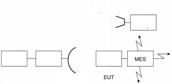
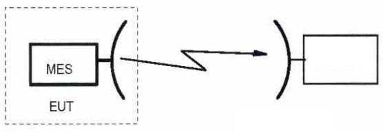
3.1.4 Measurement procedures
3.1.4.1 Measurement diagram
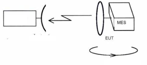

Figure 1 - Unintended emission measurement diagram, first axis
 | |||||
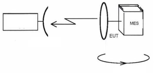
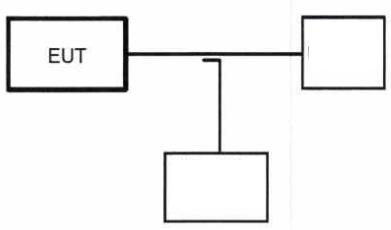
Figure 2 - Unintended emission measurement chart, second axis
 | |||||
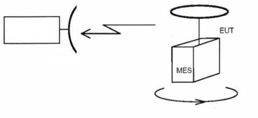
Figure 3 – Unintended emission measurement diagram, third axis
3.1.4.2 Measurements at frequencies up to 1 000 MHz
a) Measurement diagram as shown in Figure 1 with test equipment as measuring receiver. EUT adjusts the antenna in the way that the adjustment axis on the rotation plane. Adjustment axis of the antenna to be measured must coincide with the plane of adjustment rotation of EUT.
b) EUT shall be placed in a state with the carrier and the carrier shall be at a possibly lowest central frequency.
c) EUT shall be rotated 360°, the unintended emission is measured by the frequency and amplitude in the frequency range from 30 MHz to 1000 MHz. It’s required to record the frequency and amplitude of each signal.
d) The measurements must be repeated with the measuring antenna in the opposite polarization and recorded similar signal level.
e) The measurement steps as c) and d) above will be repeated when the EUT carrier is in the possibly highest central frequency.
f) The measurement steps as c) and d) above will be repeated when there is no carrier.
g) The measurement steps b) to f) above will be repeated and EUT rotates in order that the axis rotates orthogonally with the first case, as shown in Figure 2. The antenna adjustment axis of EUT shall be maintained in rotation plane.
h) The measurement step b) to f) above will be repeated and EUT rotates in order that the axis rotates orthogonally with the two first case, as shown in Figure 3. The antenna adjustment axis of EUT shall be perpendicular to the plane of the rotation plane.
3.1.4.3 Measurements at frequencies above MHz 1000
For MES that the measurements at antenna flange fail to perform or the manufacturer does not agree, EUT shall be tested with the antenna. The test shall be carried out in two phases:
- Procedure a: Identify the critical frequency of the emitting radiation is not desired.
- Procedure b: Measure the power levels of emission radiation unintended have been identified.
For MES that the measurements may perform at the antenna flange and the manufacturer agrees, EUT must be tested without antenna. The test shall be carried out in three phases:
- Procedure a): identify important frequencies of unintended emitted radiation;
- Procedure b): Measure the power levels of unintended emitted radiation already identified;
- Procedure c): Measure the emission undesired transmission.
1. Identify important frequencies of the unintended emitted radiation
a) The measurement is performed as Figure 1 and the test equipment is spectrum analyzer. EUT adjusts the antenna so that the antenna adjustment axis on rotation plane. The adjustment axis of the antenna to be measured must coincide with the plane of adjustment rotation of EUT.
b) EUT shall be placed in a carrier-on state and the carrier is in possibly lowest central frequency.
c) EUT shall be rotated 360°, the unintended emission is measured by the frequency and amplitude in the frequency range from 1000 MHz to 40 GHz. It’s required to record the frequency and amplitude of each signal.
d) The measurements must be repeated with the measuring antenna in the opposite polarization and recorded similar signal level.
e) The measurement steps as c) and d) above will be repeated when the EUT carrier is in the possibly highest central frequency.
f) The measurement steps as c) and d) above will be repeated when there is no carrier.
g) The measurement steps b) to f) above will be repeated and EUT rotates in order that the axis rotates orthogonally with the first case, as shown in Figure 2. The antenna adjustment axis of EUT shall be maintained in rotation plane.
h) The measurement step b) to f) above will be repeated and EUT rotates in order that the axis rotates orthogonally with the two first case, as shown in Figure 3. The antenna adjustment axis of EUT shall be perpendicular to the plane of the rotation plane.
2. Measurement of radiation power level of identified spurious radiation
 |
 |
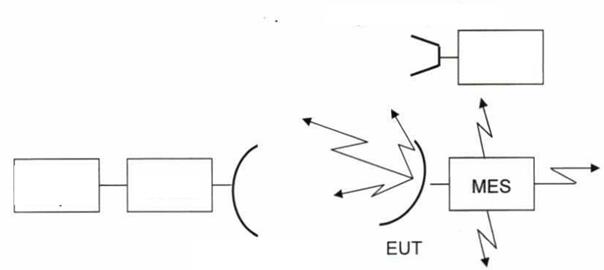
Filler
Figure 4 - Diagram measured unintended emission of EUT when antenna
a) Measurement diagram is as Figure 4 or Figure 5.
b) EUT shall be in the carrier-on state with a central frequency of the carrier-on modulated in accordance with the pre-identified unintended emission.
c) Measuring antenna must be adjusted in height and EUT rotates to get maximum response on spectrum analyzer at each identified unintended emission, the response shall be recorded.
d) Measurement diagram as Figure 1 must be repeated with the antenna measured and placed in the direction of orthogonal polarization and the response level shall be record accordingly.
e) EUT is replaced by alternative antenna, this antenna is connected to the signal generator. The main lobe axis of the antenna and the alternative antenna must be aligned.
f) Polarization of the measuring antenna and alternative antenna shall be aligned in the same way in order to generate the maximum response between EUT and measuring antenna following the steps c) and d).
g) Output signal of the signal generator shall be adjusted so that the receiving rate is equal to the largest spurious radiation recorded earlier.
 h) Record the output level of the signal generator. EIRP of unintended emission is equal to total of output signal of signal generator plus isotropic gain of the alternative antenna minus cable loss, in dB.
 | |||||||
 | |||||||
 | |||||||
Figure 5 – Unintended emission measuring diagram of EUT when there is no antenna
3. Unintended emission measurement transmitted at the antenna flange
Measurement procedures:
 | |||||||||||
 | |||||||||||
 | |||||||||||
 | |||||||||||
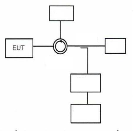
Figure 6 - Transmitting unintended emission Measurement diagram
a) The measurement diagram is shown in Figure 6. It’s needed to use a base block filter with the set frequency equal to transmitting carrier-on frequency to protect the spectrum analyzer while ensuring the accuracy of measurement, especially near the carrier-on frequency.
b) The frequency range from 1000 MHz to 40 GHz shall be reviewed to check for unintended radiation when it’s in carrier-on state at maximum power level and standard modulation. The specified unintended emission power shall be measured.
c) A. To get EIRP maximum gain discovered the largest measuring antenna at the frequency emitted unintended identifiers must be added to the power density measured and the correction factor and grafted charged to results. If the consent of the manufacturer, it will be accepted with the greatest antenna gain measured under 3.4.3.2 is used instead of the largest gain of the antenna at the frequency of unintended emissions identified.
d) The measurements must be repeated at carrier-off state.
3.2 Unintended emissions in the table
3.2.1 Measurement methods
For testing, the EUT including:
a) For IE:
- EME;
- IME;
- Connection cable between IME and EME system;
- Necessary power cables and other cables for the terminal to work well.
b) For PE:
- A PE module, this module includes auxiliary equipment in order that it has a normally operating configuration;
- Many PE modules, all modules and all necessary connection cables provided by the manufacturer include also auxiliary equipment for the system to operate normally.
The distance between EUT or alternative antenna and measuring antenna shall ensure that near-field radiations of each antenna are not coincident. The larger near-field radiations of EUT and alternative antenna are used to determine the minimum distance between EUT and measuring antenna in the first case.
3.2.1.1 General requirements
For MES, when the test may be performed at the antenna flange and get the consent of the manufacturer, the measurements are made at the antenna flange.
For MES, when the test fails to perform at the antenna flange or not get the consent of the manufacturer, the measurements are done with the measuring antenna.
3.2.1.2 Measurement methods at the antenna flange
a) Measurement diagram as Figure 7.
b) Test in the frequency range from 14.00 GHz to 14.25 GHz. For carrier-on state, the measurements aren’t made in the nominated band. The measurements shall be made while transmitting modulated carrier at maximum capacity. The carrier frequency is as close to the lower limit of operating frequency range of EUT as possible.
c) The resolution band of spectrum analyzer shall be set by the prescribed measurement band or as close as possible. If the resolution band is different from specified measurement band, it’s required to perform band adjustment for bandwidth spurious radiation like background noise.
 d) To obtain the unintended emission power level on transmitted measurement axis, increased transmission gain of isotropic antenna shall be added to each above measurement result and calibration factors will be calculated to the result.
 |
 |
Figure 7 – Diagram of unintended emission measurement on axis at the antenna flange
e) The gain of the antenna is measured in Article 3.4.3.2.
f) The measurement steps from b) to e) shall be repeated at carrier-off state.
g) The measurement steps from b) to f) shall be repeated with the transmission frequency near the upper limit of the operating frequency band of EUT.
3.2.1.3 Measurement method using the measuring antenna
a) Measurement diagram as Figure 8.
b) Test in the frequency range from 14.00 GHz to 14.25 GHz. For carrier-on state, the measurements aren’t made in the nominated band. The measurements shall be made while transmitting modulated carrier at maximum capacity. The carrier frequency is as close to the lower limit of operating frequency range of EUT as possible.
c) The resolution band of spectrum analyzer shall be set by the prescribed measurement band or as close as possible. If the resolution band is different from specified measurement band, it’s required to perform band adjustment for bandwidth spurious radiation like background noise.
d) EUT shall be installed with other systems, placed in the normal operating position. Connection cable are fixed by non-metallic device at a height from 0.5 m to 1.0 m.
e) The measuring antenna is adjusted in height and EUT rotates to maximally respond on the related spectrum analyzer at each identified unintended emission, then it’s required to record this response level.
f) The measuring antenna is adjusted in height and polarization and EUT rotates to maximally respond on the related spectrum analyzer at each pre-identified unintended emission, then it’s required to record this response level.
g) EUT is replaced by the alternative antenna. This antenna is connected to the signal generator. The main lobe axis of the measuring antenna and alternative antenna shall be aligned.
h) Polarization of the measuring antenna and the alternative antenna should be identically aligned to generate maximum response between EUT and the measuring antenna in steps e) and f).
i) The output signal of the signal generator must be adjusted so that its receiving rate is equal to that of previously recorded largest spurious radiation.
j) Record the output level of signal generator. EIRP of spurious radiation on axis is equal to total output signal of signal generator and the isotropic gain of the alternative antenna minus the loss of connection cable, in dB.
k) The measurement steps from d) to j) shall be repeated at carrier-off state.
 | |||||||
 |  | ||||||
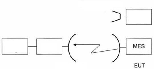
Figure 8 – Diagram of unintended emission measurement on axis by measuring antenna
3.3 Off-axis EIRP emission density in nominated band
3.3.1 General requirements
The conformity is determined from:
a) Test of rms accuracy of static directional antenna;
b) Test of Off-axis EIRP.
The off-axis EIRP test can be done in case EUT has antenna or not:
- For MES, when the test may be performed at the antenna flange and get the consent of the manufacturer, the test shall be carried out in three phases:
a) Test of output power density of transmitter (dBW / 40 kHz);
b) Test of antenna gain (dBi);
c) Test of the emitting radiation diagram of antenna (dBi).
- For MES, when the test fails to perform at the antenna flange or not get the consent of the manufacturer, EUT is equipped with the antenna. The test shall be carried out in three phases:
a) Test of maximum EIRP density above 40 kHz compared to EIRP (dBc/40 kHz);
b) Test of maximum EIRP on axis (dBW);
c) Test of emitting radiation diagram of antenna (dBi).
3.3.2 Static directional antenna rms accuracy
Measurement method
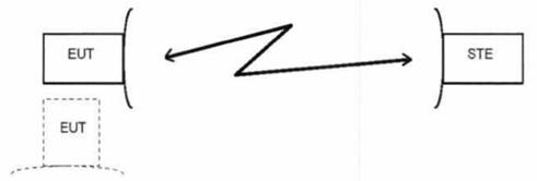
Figure 9 – Diagram of rms accuracy measurement of static directional antenna
a) The equipment shall be arranged as shown in Figure 9, two antennas in the far field of EUT rotate and stay far away from STE. Switch on STE and switch off EUT.
b) The radiation signal level from STE will be adjusted so that EUT receives power density corresponding to the ratio of signal to background noise announced by the manufacturer. This power density is expected to be 95% of MES in the system and generally higher than 2 dB over the MES coverage zone boundary designed to operate.
c) Switch on EUT and allow to get static directional position.
d) Static directional accuracy is measured and recorded. The measurement methods used will be agreed between the manufacturer and the laboratory.
e) Static directional accuracy is tracked to determine in case of directional change, it’s required to measure if rms value of this directional angle is available.
f) Static directional accuracy is measured five times.
g) Switch off EUT while EUT rotates at least 90° and in a minimum period of 1 second.
h) Repeat measurement steps from c) to f).
i) The value of the static directional rms accuracy is the maximum value of 10 recorded measurement results.
3.3.3 Off-axis EIRP measurement without antenna
3.3.3.1 Power density of the transmitter output
A. For test, EUT includes all recording devices on the flange antenna:
a) For IE:
- EME;
- IME;
- Cable connection between IME and EME system;
- Necessary power cables and other cables for the terminal to work well.
b) For PE:
- A PE module, this module includes auxiliary equipment in order that it has a normally operating configuration;
- Many PE modules, all modules and all necessary connection cables provided by the manufacturer include also auxiliary equipment for the system to operate normally.
In case EUT is designed to directly connect to the antenna flange or to the points on special equipment provided by the manufacturer and replace MES for test.
Measurement method:

 |
Figure 10 - Diagram of measuring power density of transmitter output
a) EUT is connected to the test load as shown in Figure 10.
b) For the carrier modulated by a pseudorandom binary sequence, the maximum power density provided to antenna flange shall be calculated by dBW/40 kHz. It’s required to consider the coupling coefficient of the coupler measured at measuring frequency and loss of the waveguide adapter. The resolution band of the spectrum analyzer shall be located as close to the specified measurement band as possible. If the resolution band is different from the specified measurement band, it’s required to perform the band adjustment.
3.3.3.2 Transmitting gain of antenna
1. General requirements
In this regulation, the transmitting gain of the antenna is determined by the ratio in dB of power supplied to a standard antenna, for example: an isotropic radiator in an isolated space on capacity supplied to antenna is under review, so that they create the same field intensity level at the same distance in the same direction. Without notes, the gain will be considered for the biggest radiation direction.
In this test, EUT is regarded as part of MES including the antenna and antenna flange. EUT includes a section containing electric equipment with antenna transponder (see 3.4.3.1).
2. Measuring position
The measurement is conducted at the outdoor far-field measuring position distance or reduced measuring distance. However, if the near field scanner technology converts the near field measurements into the results of the far field proven to be sufficiently accurate for both test positions, the antenna can be measure in the near field.
3. Measurement method
| |||||||
 | |||||||
 | |||||||
Figure 11 – Diagram of measuring gain of antenna
a) Measurement diagram is shown in Figure 11, EUT is connected to the measuring receiver. A signal proportional to the rotation angle position from the moving/servo structure shall be put on X axis and the signal level from the measuring receiver shall be put on Y axis of the plotter.
b) The signal radiation measuring transmitter measures on plane E firstly through horizontal polarized antenna. Main antenna lobe axis of EUT shall be aligned with the main antenna lobe axis of the measuring transmitter. The antenna or antenna polarizer of EUT shall rotate and its main lobe axis shall be adjusted so that plane E coincides with plane E of the measuring transmitter antenna.
c) When there is any change of plane E of test signal, EUT antenna shall rotate around its main lobe axis so that its plane E coincides with plane E of the measuring transmitter.
d) The frequency of the measuring signal is set to 5 MHz with the lowest frequency range that the manufacturer announces.
e) EUT shall be aligned to have the largest receiving signal and X-Y plotter shall be adjusted to obtain largest reading value on the diagram.
f) EUT shall be displaced under the azimuth angle of 10°.
g) The transmitting diagram measurement is obtained when displacing EUT in the opposite direction (compared to baseline) with an azimuth of 10 °, the plotter records the results.
h) EUT is replaced by an alternative antenna with the largest obtained signal level.
i) This receiving level is recorded on X-Y plotter.
j) The alternative antenna shall be rotated in azimuth as steps f) and g).
k) Gain of EUT is calculated as follows:
GEUT = L 1 - L 2 + C
In which GEUT: Increase the benefits of the EUT (dBi);
L1 : Obtained level with EUT (dB);
L2 : Obtained level with alternative antenna (dB);
C: Standard gain of the alternative antenna at measurement frequency (dBi).
l) The measurement steps from step e) to k) are repeated with frequency changing among lowest frequency bands announced by the manufacturer.
m) The measurement steps from step e) to k) shall be repeated with the frequency changing up to 5 MHz and lowest frequency ranges announced by the manufacturer.
n) The measurement steps from step d) to m) can be performed simultaneously.
o) The measurement steps from c) to n) shall be repeated with vertical plane E.
p) The measurement steps from c) to n) shall be repeated with plane E +45° compared to the horizontal plane.
q) The measurement steps from c) to n) shall be repeated with plane E -45° compared to the horizontal plane.
r) The measurement steps from b) to q) shall be repeated for all the frequency bands announced by the manufacturer.
3.3.3.3 Emitting radiation diagram of the antenna
1. General requirements
In this regulation, the emitting radiation diagram of the antenna is the one about the relationship of field strength under the directional angle by the antenna at a constant distance from the antenna.
In this test, EUT is regarded as part of MES including antenna and flange. The antenna includes: reflector(s), transponder, the struts and an electric equipment container and transponder located at the convergence point of the antenna (see 3.4.3.1).
2. Measuring position
The measurement is conducted at the outdoor far field measuring position distance or reduced measuring distance. However, if the near field scanner technology converts the near field measurements into the results of the far field proven to be sufficiently accurate for both test positions, the antenna can be measure in the near field.
3. Measurement method
a) Measurement diagram is shown in Figure 12, EUT is connected to the measuring receiver. A signal proportional to the rotation angle position from the moving/servo structure shall be put on X axis and the signal level from the measuring receiver shall be put on Y axis of the plotter
Measuring antenna Plotter X-Y Measuring receiver Measuring transmitter Signal transmitter 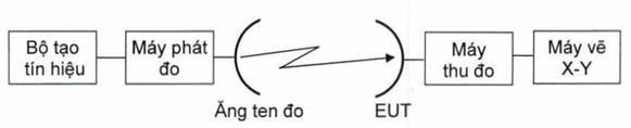
Figure 12 – Diagram of measuring emitting radiation of the antenna
b) The signal radiation measuring transmitter measures on plane E firstly through horizontal polarized antenna. Main antenna lobe axis of EUT shall be aligned with the main antenna lobe axis of the measuring transmitter. The antenna or antenna polarizer of EUT shall rotate and its main lobe axis shall be adjusted so that plane E coincides with plane E of the measuring transmitter antenna.
c) When there is any change of plane E of test signal, EUT antenna shall rotate around its main lobe axis so that its plane E coincides with plane E of the measuring transmitter.
d) The frequency of the measuring signal is set to 5 MHz with the lowest frequency range that the manufacturer announces.
e) EUT shall be aligned to have the largest receiving signal and X-Y plotter shall be adjusted to obtain largest reading value on the diagram.
f) EUT shall be displaced under the azimuth angle of 180°.
g) The transmitting diagram measurement is obtained when displacing EUT in the opposite direction (compared to baseline) with an azimuth of 10°, the plotter records the results.
h) The measurement steps from c) to g) are repeated with the frequency changing between the lowest frequency bands that the manufacturer announces.
i) The measurement steps from c) to g) are repeated with the frequency changing up to 5 MHz with the lowest frequency range that manufacturer announces.
j) The measurement steps from c) to i) may be performed simultaneously.
k) The measurement steps from c) to j) shall be repeated with vertical plane E.
l) The measurement steps from c) to j) shall be repeated with plane E at +α° compared to the vertical plane. α° is defined as the angle in the worst case between the horizontal plane and longitudinal geostationary orbit as stated by the manufacturer.
m) The measurement steps from c) to j) shall be repeated with plane E at -α° compared with horizontal plane, α° is defined in measurement step I).
n) The measurement steps from c) to m) shall be repeated for all frequency bands that the manufacturer announces.
3.3.3.4 Calculation of results
The results shall be calculated through bringing out a "mask" with the limits specified in the reference level equal to total of transmitting output power density and gain of the antenna. This reference level shall be set at a biggest point of the diagrams obtained from the emitting radiation diagram measurement in order to affirm that the off-axis EIRP density lies in the mask, in accordance with technical requirements.
3.3.4 Measurement of off-axis EIRP with antenna
3.3.4.1 General requirements
Apply the requirements of Articles from 3.2.1 to 3.2.3.1.2 for measurements over 1000 MHz.
3.3.4.2 EIRP density ratio is maximally 40 kHz to EIRP
To perform all measurements, EUT shall be MES with antenna.
Measurement method:
a) Measurement diagram is as shown in Figure 13, two antennas face each other.
b) The carrier is modulated by a pseudorandom binary sequence. The transmission will be continuously performed to the possible place.
c) The set resolution band of the spectrum analyzer is larger than but the occupancy of transmitting signal is increasingly good when it’s increasingly close to the band. Total obtained capacity P1 is measured in dBW.
d) The resolution band of the spectrum analyzer shall be set by the measuring band of 40 kHz as specified or as close as possible. If the resolution band is different from the specified measuring band, it’s required to perform the band adjustment. Maximum value P2 is the power received at 40 kHz band in the occupied band, the measurement unit is dBW.
e) Maximal EIRP density ratio of 40 kHz to EIRP (dBc/40 kHz) is (P1 - P2).
| ||||
| ||||
Figure 13 - Diagram of measuring radiated power density
3.3.4.3 Maximal on-axis EIRP
1. General requirements
To perform the measurement, EUT shall be MES with antenna.
The distance between EUT or alternative antenna and measuring antenna shall be such that the near-field radiations of each antenna aren’t coincident. The larger near-field radiations of EUT and alternative antenna are used to determine the minimum distance between EUT and measuring antenna in the first case.
2. Measuring position
The measurement is conducted at the outdoor far-field measuring position distance or reduced measuring distance. However, if the near field scanner technology converts the near field measurements into the results of the far field proven to be sufficiently accurate for both test positions, the antenna can be measure in the near field.
3. Measurement method
a) Measurement diagram is as shown in Figure 14, two antennas face each other. A signal proportional to the rotation angle position from the moving/servo structure shall be put on X axis and the signal level from the measuring receiver shall be put on Y axis of the plotter.
b) EUT transmits the carrier, at maximum capacity, and modulated by a pseudorandom binary sequence. The transmission shall be continuously performed when possible.
c) The set resolution band of the spectrum analyzer is larger than but the occupancy of transmitting signal is increasingly good when it’s increasingly close to the band.
d) Measuring signal radiation on the first plane E of EUT through its horizontally polarized antenna. Main lobe axis of the receiver antenna shall be aligned with the main lobe axis of the EUT antenna. The measuring receiver’s antenna its polarizer shall be rotated and its main lobe axis shall be adjust in the way that plane E is coincident to plane E of EUT.
Measuring receiver Plotter X-Y Measuring antenna Signal transmitter Alternative antenna
Figure 14 - Diagram measurements collected maximum EIRP axis
e) When there is any change of plane E of test signal, the measuring receiver antenna shall rotate around its main lobe axis so that its plane E coincides with plane E of the measuring transmitter.
f) The frequency of the measuring signal is set to 5 MHz with the lowest frequency range that the manufacturer announces.
g) EUT shall be aligned to have the largest receiving signal and X-Y plotter shall be adjusted to obtain largest reading value on the diagram.
h) EUT shall be displaced under the azimuth angle of 10°.
i) The transmitting diagram measurement is obtained when displacing EUT in the opposite direction (compared to baseline) with an azimuth of 10 °, the plotter records the results.
j) EUT is replaced by a signal generator connected to an adjusted antenna (alternative antenna), transmits the carrier at the frequency equal to the EUT carrier-on frequency. The obtained signal level is maximum.
k) The receiving level shall be recorded on X-Y plotter.
l) The transmitter with alternative antenna shall rotate in the azimuth as the steps from h) and i).
m) EIRP of the radiation signal from EUT shall be calculated as follows:
EIRPEUT = L1 - L2 + G + P
In which:
- EIRPEUT is EIRP of radiation signal from EUT (dBW), towards the direction of consideration;
- L1 is the obtained level with EUT (dBW) in the same direction of consideration;
- L2 is obtained level with a signal generator of alternative antenna (dBW);
- G is the adjusted gain of the alternative antenna at measuring frequency (dBi);
- P is the power generated by the signal generator in the flange of the alternative antenna (dBW).
n) The measurement steps from g) to m) are repeated with the frequency changing between the lowest frequency bands that the manufacturer announces.
o) The measurement steps from g) to m) are repeated with the frequency changing up to 5 MHz with the lowest frequency range that the manufacturer announces.
p) The measurement steps from g) to o) can be performed simultaneously.
q) The measurement steps from g) to p) shall be repeated with the vertical plane E.
r) The measurement steps from g) to p) shall be repeated with the plane E + 45 ° compared to the horizontal plane.
s) The measurement from step g) to p) shall be repeated with plane E -45 ° compared to the horizontal plane.
t) The measurement steps from g) to s) will be repeated for all frequency bands that the manufacturer announces.
u) Maximal on-axis EIRP of radiation signal by EUT is the maximum value of values calculated in step m).
3.3.4.4 Emitting radiation diagram of the antenna
1. General requirements
In this regulation, the emitting radiation diagram of the antenna is the one about the relationship of field strength under the directional angle by the antenna at a constant distance from the antenna.
To perform the measurement, EUT shall be MES with antenna.
The distance between EUT or alternative antenna and measuring antenna shall be such that the near-field radiations of each antenna aren’t coincident. The larger near-field radiations of EUT and alternative antenna are used to determine the minimum distance between EUT and measuring antenna in the first case.
2. Measuring position
The measurement is conducted at the outdoor far-field measuring position distance or reduced measuring distance. However, if the near field scanner technology converts the near field measurements into the results of the far field proven to be sufficiently accurate for both test positions, the antenna can be measure in the near field.
3. Measurement method
a) Measurement diagram is as shown in Figure 15, two antennas face each other. A signal proportional to the rotation angle position from the moving/servo structure shall be put on X axis and the signal level from the measuring receiver proportional to the obtained power (dBW) shall be put into Y axis of the plotter.
b) EUT transmits the carrier modulated by a pseudorandom binary sequence. The transmission shall be continuously performed when possible.
c) The set resolution band of the spectrum analyzer is larger than but the occupancy of transmitting signal is increasingly good when it’s increasingly close to the band.
d) Measuring signal radiation on the first plane E of EUT through its horizontally polarized antenna. Main lobe axis of the receiver antenna shall be aligned with the main lobe axis of the EUT antenna. The measuring receiver’s antenna its polarizer shall be rotated and its main lobe axis shall be adjust in the way that plane E is coincident to plane E of EUT.
Measuring antenna Plotter X-Y Measuring receiver
Figure 15 – Diagram of measuring emitting radiation of the antenna
e) When there is any change of plane E of test signal, EUT antenna shall rotate around its main lobe axis so that its plane E coincides with plane E of the measuring transmitter.
f) The frequency of the measuring signal is set to 5 MHz with the lowest frequency range that the manufacturer announces.
g) EUT shall be aligned to have the largest receiving signal and X-Y plotter shall be adjusted to obtain largest reading value on the diagram.
h) EUT shall be displaced under the azimuth angle of 180°.
i) The transmitting diagram measurement is obtained when displacing EUT in the opposite direction (compared to baseline) with an azimuth of 360°, the plotter records the results.
j) The measurement steps from g) to i) are repeated with the frequency changing between the lowest frequency bands that the manufacturer announces.
k) The measurement steps from g) to i) are repeated with the frequency changing up to 5 MHz with the lowest frequency range that the manufacturer announces.
l) The measurement steps from g) to k) can be performed simultaneously.
m) The measurement steps from e) to l) shall be repeated with the vertical plane E.
n) The measurement steps from e) to l) shall be repeated with plane E at +α° compared to the vertical plane. α° is defined as the angle in the worst case between the horizontal plane and longitudinal geostationary orbit as stated by the manufacturer.
o) The measurement steps from e) to l) shall be repeated with plane E at -α° compared with horizontal plane, α° is defined as n).
p) The measurement steps from e) to o) shall be repeated for all frequency bands that the manufacturer announces.
3.3.4.5 Calculation of results
The results shall be calculated through bringing out a "mask" with the limits specified in the reference level equal to total of transmitting output power density and gain of the antenna. This reference level shall be set at a biggest point of the diagrams obtained from the emitting radiation diagram measurement in order to affirm that the off-axis EIRP density lies in the mask, in accordance with technical requirements.
3.4 Control and monitoring
If EUT is MES that has been corrected by the manufacturer to perform these measurements with full documentation proving that the corrections exactly simulates the measuring conditions as required.
To perform these measurements, EUT is MES with or without antenna.
Measurement of EIRP spectral density shall be limited in nominal band scope or of 10 MHz bandwidth with its center in a carrier-on frequency, whichever is greater.
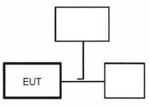
3.4.1 Measurement diagram
Measurement diagram is as shown in Figure 16 or Figure 17. EUT shall be permitted to transmit and in a state of "transmission allowance" when starting each measurement. Unless other states, storage two-ray oscilloscope shall monitor and measure the difference in time between commands or damages, and the appearance of desired events (e.g. suppression of transmission). Power meter and spectrum analyzer shall display the output level of EUT.
Oscilloscope Power meter Command Error Spectrum analyzer STE/Load
Figure 16 – Shared measurement diagram for measurements on monitoring and control in terms of radiation measurements
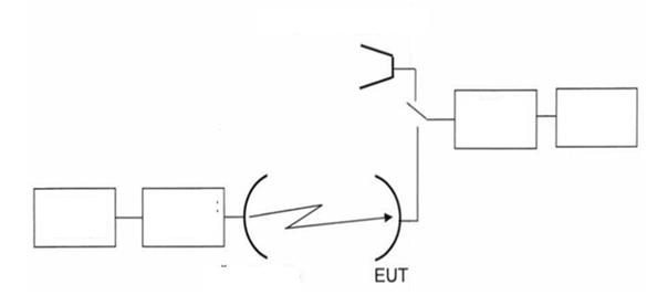
Command Error Oscilloscope Power meter Spectrum analyzer STE/Load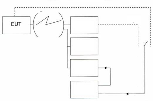
Figure 17 – Shared measurement diagram for measurements on monitoring and control in terms of radiation measurements
3.4.2 Processor monitoring
Measurement method:
a) Each processor in ETU is broken down in turn.
b) In about 1 second of failure, EUT is suspended in transmission (see on the spectrum analyzer).
c) It’s required to observe the power meter and spectrum analyzer to make sure that the transmission has been suppressed.
d) It’s required to restore the processor failure on normal working condition and shall automatically recover EUT in normal working condition before damaging next processor.
3.4.3 Transmission subsystem monitoring
Measurement method:
a) The frequencies of the subsystem shall be broken down on:
1) Frequency stability;
2) Output.
b) In about 6 seconds of failure, EUT is suspended in transmission (observed on a spectrum analyzer).
c) It’s required to observe the power meter and spectrum analyzer to make sure that the transmission has been suppressed.
d) It’s required to restore the failed components of normal working condition and restore EUT on normal working condition before causing further failure.
3.4.4 Power on
Measurement method:
a) Turn off EUT and STE doesn’t not transmit the control channel;
b) Turn on EUT;
c) Do not transmit EUT in and after turn on power and it’s required to switch to the carrier-on state;
The events from a) to c) shall be shown and confirmed by oscilloscope and transmitting signal measurement. If there is manual power on function, the following measurements shall be performed:
d) Turn on EUT and STE can transmit CC;
e) A call shall be initiated from EUT and EUT shall switch to the carrier-on state;
f) Initialize power on function;
g) EUT shall switch to the carrier-off state.
The events from e) to g) shall be shown and confirmed by oscilloscope and transmitting signal measurement.
3.4.5 Control channel (CC)
Measurement method:
The following measurements are made:
- EUT not receiving CC;
- EUT losing CC during the period of call;
- EUT losing CC during period of non-transmission;
- EUT loses CC and a call is initiated within the timeout T1.
Timeout T1 used in this measurement is 30 seconds.
a) EUT not receiving CC:
a1) Turn off EUT and STE does not transmit CC;
a2) Turn on EUT;
a3) Initiate a call from EUT;
a4) EUT shall remain the carrier-on state.
The events from a1) to a4) shall be shown and confirmed by oscilloscope and transmitting signal measurement.
b) EUT losing CC during the period of call:
b1) Turn on EUT and STE must transmit CC;
b2) Initiate a call from EUT;
b3) STE must stop transmitting CC;
b4) During timeout T1 from b3), EUT shall switch to the carrier-off state.
The events from b2) to b4) shall be displayed and confirmed by oscilloscope and transmitting signal measurement.
c) EUT losing CC during the period of non-transmission:
c1) Turn on EUT and STE transmits CC;
c2) STE stops transmitting CC;
c3) After timeout T1, initiate the call from EUT;
c4) EUT shall remain the carrier-off state.
The events from c2) e to c4) shall be shown and confirmed by oscilloscope and transmitting signal measurement.
d) If CC is lost by EUT and a call is conducted during timeout T1:
d1) Turn on EUT and STE shall transmit CC;
d2) STE shall stop transmitting CC;
d3) During the timeout T1 from step d2), EUT initiates a transmission request;
d4) EUT can transmit but during timeout T1, EUT shall switch to the carrier-off state.
The events from d2) to d4) shall be shown and confirmed by oscilloscope and transmitting signal measurement.
3.4.6 Network control command
Measurement method:
The following measurements shall be implemented in order:
- Transmission allowing command;
- Transmission prohibiting command;
- Identification/definition requirement.
a) Transmission allowing command:
a1) Turn on EUT and STE will transmit CC;
a2) EUT shall switch to carrier-off state;
a3) Initiate a call, EUT shall remain carrier-off state;
a4) STE shall give one allowing command to EUT;
a5) EUT initiates a call.
a6) EUT shall switch to carrier-on status and shall transmit.
The events from a2) to a6) shall be displayed and confirmed by oscilloscope and transmitting signal measurement.
b) Transmission prohibiting command:
b1) Continue from step a6);
b2) STE shall transmit a transmission prohibiting command to EUT;
b3) EUT shall switch to the carrier-off state within 1 second;
b4) EUT initiates a call;
b5) EUT must remain in the carrier-off state;
b6) STE shall transmit an allowing command;
b7) EUT initiates a call;
b8) EUT shall switch to the carrier-on state and shall transmit;
b9) EUT terminate the call.
The events from b2) to b9) shall be shown and confirmed by oscilloscope and transmitting signal measurement.
c) Identification request:
c1) Continue from step B9);
c2) STE will transmit identification request;
c3) EUT shall switch to the carrier-on state and will play its identifier.
EUT sends identifier displaying in STE.
3.4.7 Initialization cluster transmission
Measurement method:
a) Turn off EUT and STE transmits CC;
b) Turn on EUT;
c) EUT does not transmit, except initialization cluster, if any;
d) Each initialization cluster will not last longer than 1 second, and initialization cluster transmission shall not exceed 1% of the time.
The events from b) to d) shall be shown and confirmed by oscilloscope and transmitting signal measurement.
3.5 Diagram of off-axis gain of receiving antenna
3.5.1 Measurement position
The measurement is conducted at the outdoor far-field measuring position distance or reduced measuring distance. However, if the near field scanner technology converts the near field measurements into the results of the far field proven to be sufficiently accurate for both test positions, the antenna can be measure in the near field. Fully automated system can be used for the tests of providing results proved to be accurate, if they have been made by the specified method.
3.5.2 Measurement method
Plotter X-Y Measuring receiver Measuring antenna Measuring transmitter Signal transmitter
Figure 18 – Measurement diagram –Measurement of receiving diagram of antenna
a) The measurement diagram is shown in Figure 18, connected to the measuring receiver.
b) Measurement diagram is shown in Figure 12, EUT is connected to the measuring receiver. A signal proportional to the rotation angle position from the moving/servo structure shall be put on X axis and the signal level from the measuring receiver shall be put on Y axis of the plotter.
c) The measurement frequency shall be a central frequency of each applied frequency band. Plane E shall be placed vertically.
d) EUT shall be aligned to have the largest receiving signal and X-Y plotter shall be adjusted to obtain largest reading value on the diagram.
e) EUT shall be displaced under the azimuth angle of 180°.
f) The transmitting diagram measurement is obtained when displacing E in an azimuth of 360°, the plotter records the results.
g) The measurement steps from b) to e) are repeated with the frequency changing to lower limit of the applicable frequency bands that the manufacturer announces.
h) The measurement steps from b) to e) are repeated with the frequency changing to upper limit of the applicable frequency range that manufacturer announces.
i) The measurement steps from b) to h) are repeated with the changing frequency and other regulations if there is in the design of equipment but it’s no need to perform simultaneously in all frequency bands.
j) The measurement steps from b) to h) shall be repeated with test signal transmitted in plane H instead of plane E.
k) The measurement steps from b) to h) shall be repeated with the test signal transmitted in plane 450 compared to plane H.
l) The measurement steps from b) to h) shall be repeated with the test signal transmitted in plane 900 compared to plane in k).
m) The measurement steps from b) to l) shall be repeated among angles φr and 70 , in which EUT rotates 900 or measuring antenna or secondary polarization systems of EUT rotates 900 to provide diagonal polarized measurements.
6.5.1.3 Calculation
The result calculation is accomplished by creating a "mask" with the specified limits under the reference rate calculated by the gain of the antenna. This reference level should be set at the largest point of the diagram obtained from the diagram measurement.
3.6 Block performance
Measurement method
a) The output signals of two signal generators are combined with equal weight. The combined signals shall be combined with LNB inputs in a reasonable and appropriate way.
b) A spectrum analyzer must be connected to the LNB output, allowing to supply LNB power.
c)fc isthe central frequency of the receiving frequency band.
d) The first signal of generator frequency will be set tofc .
e) The first signal of transmitter level must be set to a level within the operation input level of LNB.
f) The spectrum analyzer is set to measure the first signal level switched at LNB output.
g) The second signal of transmitter frequency shall be set asfc - 20 MHz.
h) The second signal of transmitter level shall be adjusted so that the measurement level is 1 dB, lower when there is no second signal.
i) The second signal of transmitter level shall be recorded as the reference level.
j) The second signal of transmitter frequency shall be set with the frequency of interest.
k) The second signal of transmitter level shall be adjusted so that the measurement level is 1 dB, lower when there is no second signal.
l) Rejection of frequency of interest is equal to the second signal of the transmitter level minus the reference level determined in step i).
m) The steps from j) to l) shall be repeated with the frequencies in the range of Table 3.
NOTE: Rejection of worst case in a specific frequency range can be determined after step i) by scanning second signal of the transmitter frequency in the frequency band and observing the gain, then performing steps from j) to l) with the frequency having the highest gain.
3.7 Contiguous signal selection
Measurement method
a) Use two test signal generators. Each signal generator shall generate a modulated signal in the input frequency range and thermal noise.
b) The signal generators are connected to the IME input through a separator (combined).
c) The measuring signal generators shall be set to the frequency and level under Table 4.
d) IME shall be set to receive the signal of the first measuring signal generator.
e) The second measuring signal generators shall be set with cut-off signal.
f) The noise level (or the ratio of signal to noise) of the first measuring signal generator shall be changed to determine standard sensitivity threshold.
g) The second signal generator is set to cut-on signal.
h) Noise meter (or ratio of signal to noise) of the first measuring signal generator shall be changed to determine the standard sensitivity threshold.
i) The decrease in noise level (or the ratio of signal to noise) determined in step h) subtracts the noise level (or the ratio of signal to noise) determined in step f).
j) The result is to find the highest decline.
4 PROVISIONS ON MANAGEMENT
4.1. The mobile earth station devices within the governing scope specified in Article 1.1 shall comply with the technical requirements of this regulation.
4.2. Organizations and individuals are allowed to use the measurement results of the laboratories accredited under ISO/IEC 17025 for the requirements in Article 2.2.3 to perform the conformity certification and conformity announcement. The test for the other technical requirements of the regulation (except article 2.2.3) to perform the conformity certification and conformity announcement shall comply with the applicable law.
5 RESPONSIBILITIES OF ORGANIZATIONS AND INDIVIDUALS
The related organizations and individuals shall implement the provisions of the conformity certification and conformity announcement on mobile earth station devices operating in the Ku band and subject to examination by the state management body under the current law.
6 ORGANIZATION AND IMPLEMENTATION
6.1. Department of Telecommunications and the Information and Communications Department shall guide and organize the deployment of device management in accordance with this regulation.
6.2. In case there is any change, supplement and replacement in the provisions as stated in this regulation, the provisions as stated in the new document shall be applied.
6.3. During implementing this regulation, if there is any problem arising and entanglement, the related organizations and individuals shall reflect such that in writing to the Ministry of Information and Communications (Department of Science and Technology) for guidance and settlement. /.
LIST OF REFERENCES
[1] ETSI EN 301 427 V2.1.1 (2016-06): “Satellite Earth Stations and Systems (SES): Harmonized EN for Low data rate Mobile satellite Earth Stations (MES) except aeronautical mobile satellite earth stations, operating in the 11/12/14 GHz frequency bands covering essential requirements under article 3.2 of the R&TTE directive”.
You are not logged in.
This feature is available to Advanced account holders. Please log in to access detailed information on Related documents.
If you do not have an account, please register here!
VIETNAMESE DOCUMENTS
This utility is available to subscribers only. Please log in to a subscriber account to download. Don’t have an account? Register here
This utility is available to subscribers only. Please log in to a subscriber account to download. Don’t have an account? Register here
This utility is available to subscribers only. Please log in to a subscriber account to download. Don’t have an account? Register here
ENGLISH DOCUMENTS
This utility is available to subscribers only. Please log in to a subscriber account to download. Don’t have an account? Register here

