Circular 17/2023/TT-BTTTT QCVN 55:2023/BTTTT on Short-Range Radio Equipment in the Frequency Band from 9 kHz to 25 MHz and Inductive Loop Equipment Operating in the Frequency Band from 9 kHz to 30 MHz
- Summary
- Content
- Status
- Vietnamese
- Related documents
- Diagram
- Download
Please log in to your Advanced Package to view the full text. Do not have an account yet? Register here.
Please log in to use this function
Please log in to use this function
ATTRIBUTE
| Issuing body: | Ministry of Information and Communications | Effective date: | Known Please log in to a subscriber account to use this function. Don’t have an account? Register here |
| Official number: | 17/2023/TT-BTTTT | Signer: | Nguyen Manh Hung |
| Type: | Circular | Expiry date: | Updating |
| Issuing date: | 27/11/2023 | Effect status: | Known Please log in to a subscriber account to use this function. Don’t have an account? Register here |
| Fields: | Information - Communications |
The Effect status of this document is known.This feature is available to Advanced account holders. Please log in to a subscriber account to view Effect status. Don’t have an account? Register here
THE MINISTRY OF INFORMATION AND COMMUNICATIONS ------------------------- No. 17/2023/TT-BTTTT | THE SOCIALIST REPUBLIC OF VIETNAM ------------------------- Hanoi, November 27, 2023 |
CIRCULAR
Promulgating the “National Technical Regulation on Short-Range Radio Equipment in the Frequency Band from 9 kHz to 25 MHz and Inductive Loop Equipment Operating in the Frequency Band from 9 kHz to 30 MHz”
-------------------------
Pursuant to the Law on Standards and Technical Regulations dated June 29, 2006;
Pursuant to the Law on Telecommunications dated November 23, 2009;
Pursuant to the Law on Radio Frequency dated November 23, 2009, and the Law Amending and Supplementing Certain Articles of the Law on Radio Frequency dated November 9, 2022;
Pursuant to Decree No. 127/2007/ND-CP dated August 1, 2007, of the Government detailing and guiding the implementation of certain articles of the Law on Standards and Technical Regulations;
Pursuant to Decree No. 78/2018/ND-CP dated May 16, 2018, of the Government amending and supplementing certain articles of Decree No. 127/2007/ND-CP dated August 1, 2007, of the Government detailing the implementation of certain articles of the Law on Standards and Technical Regulations;
Pursuant to Decree No. 48/2022/ND-CP dated July 26, 2022, of the Government prescribing the functions, tasks, powers, and organizational structure of the Ministry of Information and Communications;
At the proposal of the Director of the Department of Science and Technology,
The Minister of Information and Communications hereby issues this Circular to promulgate the National Technical Regulation on Short-Range Radio Equipment in the Frequency Band from 9 kHz to 25 MHz and Inductive Loop Equipment Operating in the Frequency Band from 9 kHz to 30 MHz.
Article 1. Issued together with this Circular is the “National Technical Regulation on Short-Range Radio Equipment in the Frequency Band from 9 kHz to 25 MHz and Inductive Loop Equipment Operating in the Frequency Band from 9 kHz to 30 MHz” (QCVN 55:2023/BTTTT).
Article 2. Effect
1. This Circular takes effect from July 1, 2024.
2. Clause 15, Article 1 of Circular No. 29/2011/TT-BTTTT dated October 26, 2011, of the Minister of Information and Communications, shall cease to be effective as of July 1, 2024.
Article 3. The Chief of the Office, the Director of the Department of Science and Technology, heads of agencies and units under the Ministry of Information and Communications, Directors of the Departments of Information and Communications of provinces and centrally governed cities, and relevant organizations and individuals are responsible for implementing this Circular.
| MINISTER
(Signed and sealed)
Nguyen Manh Hung |
SOCIALIST REPUBLIC OF VIETNAM
QCVN 55:2023/BTTTT
National technical regulation on Short Range Device (SRD) - Radio equipment to be used in the 9 kHz to 25 MHz trequency range and inductive loop Systems in the frequency range 9 kHz to 30 MHz
HANOI – 2023 |

Preface
QCVN 55:2023/BTTTT replaces QCVN 55:2011/BTTTT.
QCVN 55:2023/BTTTT was compiled by the Vietnam Telecommunications Authority, submitted for approval by the Department of Science and Technology, appraised by the Ministry of Science and Technology and issued by the Ministry of Information and Communications together with Circular No. .... /2023/TT-BTTTT day ... month .... year 2023.
National technical regulation
on Short Range Device (SRD) - Radio Equipment to be used in the 9 kHz to 25 MHz FRequency range and inductive loop Systems
in the ừequency range 9 kHz to 30 MHz
1. GENERAL PROVISIONS
1.1. Governing scope
This regulation is applied to the following types of short range devices (SRD):
a) Short range devices for common purposes operating in 9 kHz to 25 MHz frequency range; and
b) Magnetic loop devices operating in 9 kHz to 30 MHz frequency range, including: radio frequency identification device (RFID), Near Field Communication (NFC) technology-based device and device used in Electronic Article Surveillance (EAS) operating in the LF and HF frequency ranges.
This regulation is applied to products and goods that are short range devices with HS code as specified in Appendix J.
All short range devices specified in this regulation must comply with the regulations on frequency planning and frequency demultiplex of Vietnam. The types of radio equipment listed above operate in 9 kHz to 30 MHz frequency range (as specified in Table 1) for the following cases:
- There is a radio output connection with a dedicated antenna or with an integral antenna;
- Use any type of modulation;
- Fixed station, mobile station and portable station.
Table 1 - Permitted frequency ranges for short range devices
in 9 kHz to 30 MHz frequency range
| Band/frequency | Application |
Transmit and Receive | 9 kHz ÷ 90 kHz | Sensor devices, for general purposes |
Transmit and Receive | 90 kHz ÷119 kHz | Sensor devices, for general purposes |
Transmit and Receive | 119 kHz÷ 140 kHz | Sensor devices, for general purposes |
Transmit and Receive | 140 kHz÷ 148.5 kHz | Sensor devices, for general purposes |
Transmit and Receive | 148.5 kHz÷ 190 kHz | Sensor devices, for general purposes |
Transmit and Receive | 3,155 kHz÷ 3,400 kHz | Sensor devices, for general purposes |
Transmit and Receive | 3,234 kHz ÷ 5,234 kHz | Thiết bị cảm ứng, dùng trong giao thông |
Transmit and Receive | 6,765 kHz÷6,795 kHz | Sensor devices, for general purposes |
Transmit and Receive | 10,200 MHz÷11,000 MHz | Sensor devices, for general purposes |
Transmit and Receive | 13,553 MHz÷13,567 MHz | Sensor devices, for general purposes |
Transmit and Receive | 26,957 MHz÷27,283 MHz | Sensor devices, for general purposes |
1.2. Subjects of application
This regulation is applicable to Vietnamese and foreign organizations and individuals throughout the territory of Vietnam that have production and business activities of devices within the governing scope of this regulation.
1.3. Normative references
ETSI TR 100 028 (all parts) (V1.4.1): "Electromagnetic compatibility and Radio spectrum Matters (ERM); Uncertainties in the measurement of mobile radio equipment characteristics".
CISPR 16-1-4:2010+AMD1:2012: "Specification for radio disturbance and immunity measuring apparatus and methods - Part 1-4: Radio disturbance and immunity measuring apparatus - Antennas and test sites for radiated disturbance measurements".
CEPT/ERC/REC 70-03: "Relating to the use of Short Range Devices (SRD)".
Recommendation ITU-T O.153: "Basic parameters for the measurement of error performance at bit rates below the primary rate".
Recommendation ITU-T O.41: "Psophometer for use on telephone-type circuits".
ANSI C63.5: "American National Standard for Electromagnetic Compatibility-Radiated Emission Measurements in Electromagnetic Interference (EMI) Control-Calibration of Antennas (9 kHz to 40 GHz)".
ETSI TR 102 273-2: "Electromagnetic compatibility and Radio spectrum Matters (ERM); Improvement on Radiated Methods of Measurement (using test site) and evaluation of the corresponding measurement uncertainties; Part 2: Anechoic chamber".
ETSI TR 102 273-3: "Electromagnetic compatibility and Radio spectrum Matters (ERM); Improvement on Radiated Methods of Measurement (using test site) and evaluation of the corresponding measurement uncertainties; Part 3: Anechoic chamber with a ground plane".
ETSI TR 102 273-4: "Electromagnetic compatibility and Radio spectrum Matters (ERM); Improvement on Radiated Methods of Measurement (using test site) and evaluation of the corresponding measurement uncertainties; Part 4: Open area test site".
ETSI TR 103 059 (V1.2.1): "Electromagnetic compatibility and Radio spectrum Matters (ERM); Short-Range Devices (SRD) for operation in the 13,56 MHz band; System Reference Document for Radio Frequency Identification (RFID) equipment".
1.4. Terminology Explanation
1.4.1. Artificial antenna
A dummy load adjusted for radiation, having a nominal impedance equal to the high-frequency output impedance of the device under test. This impedance value is specified by the device supplier.
1.4.2. Assigned frequency band
The frequency band in which the device is authorized to operate.
1.4.3. Conducted measurements
Measurements performed using a direct connection to the Equipment Under Test (EUT).
1.4.4. Customized antenna
An antenna fabricated following the antenna design principles of manufacturers during testing phases.
1.4.5. Dedicated antenna
A removable antenna designed as an integral part of the equipment.
1.4.6. Fixed station
Equipment intended for use at a fixed location.
1.4.7. Integral antenna
An antenna permanently attached inside the device and designed as an integral component of the device.
1.4.8. Magnetic dipole moment (for air-core coils only)
The product of (number of coil turns) × (cross-sectional area of the coil) × (current passing through the coil).
1.4.9. Inductive loop
A short-range radio device operating based on electromagnetic field principles (near-field radiation) and using low frequencies.
1.4.10. Inductive devices
Short-range radio devices employing inductive loop technology.
1.4.11. Mobile station
Equipment typically installed on motor vehicles.
1.4.12. Portable station
Equipment carried by individuals or mounted on vehicles.
1.4.13. Radiated measurements
Measurements concerning the absolute field strength of radiation.
1.4.14. Spurious emissions
Emissions at one or more frequencies outside the occupied frequency band, which may reduce safety without affecting the corresponding information transmission.
1.4.15. Short-range device
Low-power radio equipment designed for operation within narrow ranges, with minimal potential to cause harmful interference to other radio equipment when meeting specific technical and operational conditions.
1.4.16. Transponder
A device that responds to interrogation signals.
1.5. Symbol
Ω ohm
A cross-section of coil in m2
C adjustment factor
E electric field strength
f frequency
fA frequency A transmitter
fB frequency B transmitter
fC central frequency
fH highest frequency
f L lowest frequency
fc carrier frequency in Hz
H magnetic field strength
Hef magnetic field strength generated by electric field antenna
Hf magnetic field strength limit
Hc emitting H field limit
Hs H field strength for radiated spurious emissions
Ic carrier current limit
Is current limit of conductive spurious emission
λ wavelength
m magnetic dipole moment
N number of loops of the loop antenna
NB variables defined in Table 10 (see 2.5.3.3)
I current in antenna's coil
NIA product of N x I x A
P power
t time
1.6. Abbreviation
EAS | Electronic Article Surveillance |
EMC | ElectroMagnetic Compatibility |
CEPT | European Conterence of Postal and Telecommunications administrations |
ERC | European Radiocommunications Committee |
EUT | Equipment Under Test |
ITU-T | ITU-Telecommunication sector |
LF | Low Frequency |
NFC | Near Field Communication |
NRI | National Radio Interfaces |
RF | Radio Frequency |
RFID | Radio Frequency Identification |
SND/ND | Signal, Noise and Distortion over Noise and Distortion |
SRD | Short Range Device |
VSWR | Voltage Standing Wave Ratio |
2. TECHNICAL REGULATIONS
2.1. Technical requirements
2.1.1. General requirements
2.1.1.1. Receiver requirements
The requirements for checking conformity of receiver are defined in Table 2 below.
Table 2 – Receiver’s conformity check based on technology
Technology | Receiver spurious emissions (see 2.5.3) | Adjacent channel selectivity (see 2.5.1) | Intercept characteristics or receiving sensitivity reduction rate (see 2.5.2) |
Tagging system | Required | No (Note 2) | No (Note 1) |
System in the frequency range 27 MHz | Required | Required | Required |
Other systems | Required | No (Note 2) | Required |
Note 1: No intercept characteristics or receiving sensitivity reduction rate is required, because the receiver is located in the place same as the transmitter in a tagging system with Rx and Tx working simultaneously. Tx signal at Rx input is about 90 dB higher than the receiver sensitivity or tagging signal level (see ETSI TR 103 059, Figure 8). In addition, with very short communication ranges for applications (e.g. NFC, RFID), the intercept signal must be about 90 dB higher than the transmitter signal at the antenna, which is unlikely. Note 2: The adjacent channel selectivity is suitable according to the National Radio Frequency Planning with the unchanged frequency channel distance, for example: 27 MHz band. | |||
2.1.1.2. Quality Criteria
For the purpose of quality inspection, the receiver must produce an appropriate output under normal conditions as indicated below:
- SND/ND ratio of 20 dB, measured at the receiver output via a telephone weighting network as described in Recommendation ITU-T O.41; or
- After demodulation, the data signal has a bit error rate of 10-2 without any adjustment; or
- After demodulation, the message acceptance rate is 80%; or
When the above quality criteria cann’t be met, the manufacturer must declare the criteria for determining the quality of the receiver.
2.1.2. Test Equipment
For certification testing purposes, the equipment under test must fully meet all the requirements in this Standard across all operating frequencies of the equipment.
The equipment under test must declare the frequency range, operating conditions, and power requirements to establish appropriate testing conditions. Additionally, it must be accompanied by relevant technical documentation and operating instructions.
The manufacturer may provide a coupling device for equipment with an integrated antenna (see 2.3.3). For equipment without an antenna, classified as Group 3 products, the manufacturer must provide a radiation-suppressing load (see 2.3.2.1) or an artificial antenna as specified in Appendix D.
To simplify and harmonize testing procedures across different laboratories, measurements must be conducted on equipment samples meeting the requirements outlined in sections 2.1.2.1 to 2.1.2.4. In this case, the requirements set forth in this Standard will be met without requiring measurements across all frequencies.
2.1.2.1. Selection of a sample of equipment under test
The manufacturer shall provide one or more samples of equipment suitable for the test.
If the equipment has some optional functions but does not affect radio (RF) parameters, simply test the equipment with a configuration that combines all the most complex features. The equipment under test must have an output terminal with an RF impedance of 50 Ω for conducting power measurement.
In case the equipment uses an integral or internal antenna, but without a fixed RF 50 Ω terminal, a second sample of equipment with a 50 Ω impedance external antenna temporary connection is required in accordance with accordance with the test requirements (see 2.1.2.3).
2.1.2.2. Test of equipment with different radiated field strengths
If the equipment under test has a radiated field strength formed by various individual power blocks, or by addition of power stages, all of the above information must be declared in the technical documentation. Each power block or each additional power stage must be tested in conjunction with the equipment. In the simplest case, measurements of radiated field strength, spurious emissions must be made for each combination and must be recorded in the test report.
2.1.2.3. Test of equipment without an external 50 W RF terminal (equipment using integral antenna)
2.1.2.3.1. Equipment with internal permanent or temporary antenna terminal or using a separate test coupler
To aid in testing, equipment access terminals, permanent or temporary terminals should be indicated on the circuit diagram. The equipment supplier may provide suitable test couplers. The use of test couplers, internal antenna connections or specific external antenna temporary connections must be recorded in the test report.
Information about test couplers is given in 2.3.3 and Appendix A.
2.1.2.3.2. Equipment with a temporary antenna terminal
Radiation can be measured for equipment connected to a standard antenna. The equipment supplier must coordinate and support the laboratories when determining the result of the radiation measurement, dissemble the antenna and install temporary terminal to the external antenna.
In other words, there are two types of equipment to be tested in the laboratory: one that is connected to a temporary terminal, and one with an antenna being connected. Measurements are made using a combination of the above two types of equipment. The party with equipment under test must declare the same two samples of equipment in the regulation, except for the antenna terminal.
2.1.2.4. Test at installation site
In case failing to provide samples of antennas and/or equipment due to physical limitations, measurements equivalent to those described in the documentation must be performed at the equipment installation site.
2.1.3. Mechanical and electrical design
2.1.3.1. General
The transmitter and receiver can be separate blocks or are combined in a block.
2.1.3.2. Control functions
The user cannot easily access control functions, wrong control may increase the interference potential of the device.
2.1.3.3. Transmitter automatic shut-off function
If the transmitter has an automatic shut-off function, this function must be disabled during the test.
2.1.3.4. Prevention from noise reduction and battery saving functions in the receiver
If the receiver has silent, noise-cancelling or battery-saving functions, these functions must be disabled during the measurement. In case these functions cannot be disabled, an appropriate measurement method must be described and recorded.
2.1.4. Product information disclosure
When submitting the EUT for testing, the manufacturer must provide the necessary information as required by the laboratory.
2.1.5. Auxiliary test equipment
The setup information and the specific source of test signal must be included with the test equipment.
2.1.6. Interpretation of test results
Interpretation of test results when comparing measured values with limits is specified as follows:
a) When the measured value does not exceed the limit value, the equipment under test meets the requirements of this regulation.
b) When the measured value exceeds the limit value, the equipment under test fails to meet the requirements of this regulation.
c) The measured uncertainty is calculated by the technician performing the measurement must be recorded in the test report.
The measured uncertainty that is calculated by the technician may be the maximum value for a range of measured values, or it may be the uncertainty for a specific test that has not yet been measured. The used method must be recorded in the test report.
2.2. Test conditions, power supply and environmental temperature
2.2.1. Environmental Conditions
The technical requirements of this Standard apply under the operating environmental conditions declared by the manufacturer. The equipment must comply with all the technical requirements of this Standard when operating within the declared boundary limits of the environmental conditions.
2.2.2. Test power source
2.2.2.1. General
The equipment must be checked using a suitable measuring power source as specified in 2.2.2.2 or 2.2.2.3. In case of external and internal power sources, the equipment must be tested using an external power source as specified in 2.2.2.2, then repeat using internal power source as specified in 2.2.2.3.
The used test power source must be stated in the test report.
2.2.2.2. External test power source
During the test, the power source of the equipment must be replaced by an external test power source capable of producing the reference measurement voltage as in 2.2.3.2. The internal impedance of the external test power source must be low enough that the degree of influence on the test result is negligible. For measurement purpose, the voltage of the external test power supply must be measured at the inputs of the equipment. The external test power source must be suitably decoupled and applied as close to the terminals of the equipment battery as possible. For radiation measurements, any external power conductors must be arranged so as not to affect the measurements.
During the test, the measured supply voltage must be within a tolerance of < ±1 % of the voltage at the beginning of each measurement. The value of this tolerance can be very important for certain measurements. Using a smaller tolerance will provide a better uncertainty value for these measurements.
2.2.2.3. Internal test power source
For radiation measurements on portable station with integral antennas, a fully charged internal battery is recommended. Batteries in use must be provided or recommended by the manufacturer. If using internal battery, voltage must be within tolerance less than ±5 % compared to original voltage. In case of nonconformity, a note for this effect must be added to the test report.
For conductive measurements or in case of test coupler, an external power source at the specified voltage may be substituted for the batteries enclosed with the equipment. This must be recorded in the test report.
2.2.3. Normal test conditions
2.2.3.1. Normal temperature and humidity
Laboratory temperature and humidity within the range have the following values:
- Temperature: from +15 °C to +35 °C;
- Humidity: from 20% to 75%.
In case the above measurement conditions cannot be established, the test report must specify the specific parameters of the measurement environment.
2.2.3.2. Normal test power source
2.2.3.2.1. Mains
The mains voltage connected to the measuring equipment must be rated voltage.
The equipment supplier must declare the rated voltage for each specific device.
AC power supply frequency must be between 49 Hz and 51 Hz.
2.2.3.2.2. Lead-acid battery source
When radio equipment is powered by a lead-acid battery, the common measuring voltage is 1.1 multiplied by rated voltage of the battery (6V, 12V, etc.).
2.2.3.2.3. Other sources
When equipment is powered by other types of power sources, or other types of batteries, the measured voltage must be declared by the equipment supplier and approved by the laboratories. These values must be recorded in the test report.
2.2.4. Extreme test conditions
2.2.4.1. Critical temperature
Before making measurements, the equipment under test must reach thermal equilibrium in the laboratory. The equipment must be powered off during the temperature stabilization period of time.
In case equipment has a temperature-stabilizing circuit design for continuous operation, the temperature-stabilizing circuit must be switched in approximately 15 minutes after thermal equilibrium is reached, and the equipment must satisfy the specified requirements.
When thermal equilibrium cannot be checked by measurement, a minimum thermal equilibrium period of 01 hour or a period determined by the laboratory personnel must be observed. Select the order of measurements and monitor the humidity in the laboratory so that no condensation occurs.
2.2.4.1.1. Test procedure at critical temperatures
If the manufacturer declares that the equipment is designed for continuous operation, the testing procedure is as follows:
- Before testing at the upper critical temperature, the equipment must be placed in the testing chamber until thermal equilibrium is achieved. After achieving thermal equilibrium, the equipment shall be powered on and set to transmit mode for a duration of 30 minutes. Measurements are then carried out.
For testing at the lower critical temperature, the equipment must be placed in the testing chamber until thermal equilibrium is achieved. After achieving thermal equilibrium, the equipment shall be powered on for a duration of 1 minute. Subsequently, the equipment must meet the requirements of the standard.
2.2.4.1.2. Testing Procedures for Equipment Designed for Continuous Operation
If the manufacturer declares that the equipment is designed for continuous operation, the testing procedure is as follows:
- Before testing at the upper critical temperature, the equipment must be placed in the testing chamber until thermal equilibrium is achieved. After achieving thermal equilibrium, the equipment shall be powered on and set to transmit mode for a duration of 30 minutes. Measurements are then carried out.
- For testing at the lower critical temperature, the equipment must be placed in the testing chamber until thermal equilibrium is achieved. After achieving thermal equilibrium, the equipment shall be powered on for a duration of 1 minute. Subsequently, the equipment must meet the requirements of the standard.
2.2.4.1.3. Test procedure for equipment designed for intermittent operation
If the manufacturer declares that the equipment is designed for non-continuous operation, the testing procedure is as follows:
- Before testing at the upper critical temperature, the equipment must be placed in the testing chamber to achieve thermal equilibrium. Then:
+ Turn the transmitter on and off according to the operating cycle declared by the manufacturer for a duration of 5 minutes; or
+ If the manufacturer declares an operating cycle longer than 1 minute, transmit for no more than 1 minute, then switch the device to the off or standby mode for approximately 4 minutes. Subsequently, the equipment must meet the requirements of the standard.
- For tests at the lower critical temperature, place the equipment in the laboratory until thermal equilibrium is reached. When thermal equilibrium is reached, put the equipment in standby or receive mode within 1 minute, then the equipment must meet the requirements of the regulation.
2.2.4.1.4. Critical temperature range
For tests at critical temperatures, measurements must be made according to the procedures specified in 2.2.4.1.1 at the lower and higher temperatures of one of the following ranges:
- Type I (general) from -20°C to +55°C;
- Type II (handheld) from -10 °C to +55°C;
- Type III (equipment for indoor use) from 0°C to +35°C.
NOTE: The term “Equipment for indoor use” means that the indoor temperature is at least 5°C or greater.
In special applications, the manufacturer must specify a wider temperature range than the minimum specified above.
Record the temperature range used in the test report.
2.2.4.2. Extreme test power source
2.2.4.2.1. Mains
The extreme test supply voltage for equipment connected to the mains must be the rated mains voltage ±10%. For equipment operating beyond the range of mains voltages, 2.2.4.2.4 will be applied.
2.2.4.2.2. Lead-acid battery source
When radio equipment is powered by lead-acid battery types, the extreme test voltages must be 1.3 and 0.9 multiplied by the rated battery voltage (e.g. 6V or 12V).
When charging using “gel-cell” batteries, the voltage is limited to 1.15 and 0.85 multiplied by the rated voltage of the battery.
2.2.4.2.3. Other battery sources
The lower extreme test voltages for equipment using batteries other than lead-acid are as follows:
- For equipment with battery power indication, it is the indicated endpoint voltage.
- For equipment without battery power indication, the following terminal voltages shall apply:
+ For leclanche or lithium batteries: 0.85 multiplied by the rated voltage of the battery;
+ For nickel-cadmium type: 0.9 multiplied by the rated voltage of the battery.
- For other types of equipment or batteries, the lower extreme test voltage under discharged conditions shall be declared by the manufacturer.
The upper extreme test voltage, in this case, must be the rated voltage.
2.2.4.2.4 Other sources
For equipment using other power sources, or capable of operating from different power sources, the test voltages shall be declared by the equipment manufacturer and approved by the testing laboratory. These values shall be stated in the test report.
2.3. General conditions
2.3.1. Normal test signals and test modulation
2.3.1.1. General
The test modulation signal is the signal used to modulate the carrier, depending on the type of equipment under test and the required measurements. The test modulation signals are applied only to equipment with an external modulation terminal. For devices without an external modulation terminal, use modulation under progress for measurement.
2.3.1.2 Normal test signal for analog voice
The test signal for analog voice is specified as follows:
- A-M1: frequency 1 000 Hz
- A-M2: frequency 1 250 Hz.
For phase modulation, the reference level of test signals A-M1 and A-M2 must be adjusted to produce a frequency deviation equal to 12% of channel spacing or a lower value declared by the equipment supplier as operating level for measurement.
In case of amplitude modulation, the standard modulation depth is 60% or lower as declared by the equipment supplier. This value is used as operating level for measurement and must be recorded in the test report.
2.3.1.3. Normal measurement signal for data
For equipment with an external terminal for data modulation, use the standard measuring signal as follows:
a) D-M2: The test signal is a pseudo-random binary sequence of at least 511 bits, repeated continuously, in accordance with Recommendation ITU-T O.153. If the signal sequence is not repeated continuously, the actual method of application must be specified in the test report.
b) D-M3: In case of selective messages, with encoder/decoder included in the test equipment, there must be agreement between the equipment supplier and the laboratory regarding the measuring signal.
For phase modulation, the reference level of test signal D-M3 must produce a frequency deviation equal to 20% of the channel spacing or the value declared by the equipment supplier is as the operating level for measurement.
In case of amplitude modulation, the modulation ratio is 60% or the value declared by the equipment supplier is as the operating level for measurement.
2.3.2. Artificial antenna
An artificial antenna can be used to measure short range device, but it must be of the resistive load type. VSWR on 50 Ω RF terminal must not exceed 1.2:1 for the entire test frequency range.
2.3.2.1. Artificial antenna for transmitters with inductive antenna (other than 50 Ω)
For transmitter measurements with inductive antenna other than 50 , a radiation attenuating load must be used to be connected to the antenna output by agreement with the laboratory.
The dummy antenna impedance must be equal to the nominal impedance of the equipment under test, as specified by the manufacturer.
This method is intended to be used for the following conductivity measurements:
- Transmitter carrier loop current up to 30 MHz;
- Transmitter spurious emission loop current up to 30 MHz; and
- Spurious emission measurement in 30 MHz to 1 GHz range.
The use of other loads 50 must be recorded in the test report.
2.3.2.2. Artificial antenna for transmitters with 50 Ω impedance terminal
For transmitter measurements with a nominal antenna impedance of 50 , an artificial antenna of a 50 , non-radiating, resistive component-free load connected to the antenna port must be used. The voltage standing wave ratio (VSWR) is not more than 1.2:1 within the frequency range of the measurement.
This method is intended to be used for the following conductivity measurements:
- Transmitter carrier loop current up to 30 MHz;
- Transmitter spurious emission loop current up to 30 MHz; and
- Spurious emission measurement in 30 MHz to 1 GHz range.
The use of load 50 must be recorded in the test report.
2.3.3. Test coupler
Use a test coupler for equipment having an integral antenna without 50 W output terminal by agreement with the laboratory.
Test coupler is a radio-frequency coupling device for coupling an integral antenna to 50 W terminal in the operating frequency range of the equipment under test. This allows measurements to be carried out according to the conductivity measurement method.
The manufacturer is responsible for providing a complete description of the coupling device. The testing laboratory must calibrate this device by performing the required field measurements at normal temperature and at the specified testing location. Subsequently, similar measurements must be conducted on the equipment under test using the coupling device for all frequency components.
In addition, the test coupler can provide:
- Connection to an external power source;
- Audio-frequency interface is connected directly or via a mixer;
- Connection to the data interface.
The quality criteria of the test coupler must comply with the following basic parameters:
- RF coupling circuit contains no active or nonlinear components;
- The coupling loss does not affect the measurement results;
- The coupling loss is independent of the position of the test coupler and is not affected by nearby objects or people;
- The coupling loss does not change when disconnecting or reconnecting the equipment under test;
- The coupling loss does not change when the environmental conditions change.
2.3.4. Test site and general measurement layout for radiation measurements
The radiation measurement layout and detailed description are given in Appendix A.
2.3.5. Transmitter’s operating mode
For the measurements specified in this Standard, the transmitter operates in an unmodulated state. Additionally, the manufacturer and the testing laboratory must agree on the method to achieve an unmodulated carrier frequency or specific modulation patterns, and this must be documented in the measurement report.
For transmitters using a continuous broadband scanning carrier, the measurement must be performed when the scanning regime is enabled.
For this sample test (see 2.3.1.2 and 2.3.1.3), the normal test signal is applied to the input of the transmitter under test provided that the input device (e.g. microphone) is disconnected.
2.3.6. Measuring receiver
The term measuring receiver refers to a selective voltmeter or spectrum analyzer. The bandwidth and type of detection are specified in Table 3.
Table 3 - Bandwidth and detection type
Frequency (f) | Detection type | Receiver bandwidth | Spectrum analyzer bandwidth |
9 kHz f 150 kHz | Near peak | 200 Hz | 300 Hz |
150 kHz f 30 MHz | Near peak | 9 kHz | 10 kHz |
30 MHz f 1 000 MHz | Near peak | 120 kHz | 100 kHz |
NOTE: For the measurement of the frequency ranges from 6,765 MHz ≤ f ≤ 6,795 MHz and 11,810 MHz ≤ f ≤ 15,310 MHz, the measurement bandwidth must be from 200 Hz to 300 Hz. | |||
In exceptional cases, other bandwidths may be used with the approval of the laboratory. This must be recorded in the test report.
2.4. Requirements for transmitter
2.4.1. Transmitter classification
Transmitters are classified into product types based on the used type of antenna. For type 2 and type 3 product group transmitters, a separate loop antenna may be used based on the design guidelines given in the manufacturer's instructions for use. These guidelines are evaluated by the laboratory as part of the equipment testing process and compared with actual radiation measurements.
2.4.1.1. Inductive antenna transmitter
This transmitter is characterized by:
a) Antenna inductor cross-section A < 30 m2 ;
b) Length of any loop antenna element < λ/4 (< 75/f where f is calculated in MHz) or < 30 m, whichever is less;
c) Antenna inductors can have one or more loops.
2.4.1.2. Big-size inductive antenna transmitter
This transmitter is characterized by:
- Large antenna inductor cross-section A > 30 m2;
- Antenna has only one ring;
- Frequency range is limited from 9 kHz to 135 kHz.
2.4.1.3. Other transmitters
This transmitter is characterized by:
- E field transmitters, or
- Inductive antenna transmitters that do not meet the criteria in 2.4.1.1 and 2.4.1.2.
2.4.1.4. Types of products
Equipment is classified according to used type of antenna. Product types do not cause confusion with receiver types (see 2.1.1.1). For different antenna types, refer to Recommendation CEPT/ERC 70-03.
Product types include:
Type 1 product:
Transmitter with inductive antenna, tested by antenna or:
- Integral antenna (type 1 antenna); or
- Separate antenna supplied with equipment (type 2 antenna). The following limitations are applied to this product type:
+ Frequency range is from 9 kHz to 25 MHz;
+ The antenna field is not designed according to customer's request;
+ Antenna loop cross-section < 30 m2 ; and
+ The length of an antenna loop element is less than the smallest value of the following two values: < λ/4 (< 75/f where f is calculated in MHz) or < 30 m.
The transmitter carrier output limits and spurious emission limits are specified in Sections 2.4.8.4, 2.4.9.3 and 2.4.10.3, respectively.
If the standard antennas are supplied by the manufacturer, the equipment must be tested as a type 1 product with the attached antennas. Measurements must be repeated with each such antenna.
Type 2 product:
The transmitters have an inductive antenna, which allows the antenna's field to be changed.
Change is only permitted in accordance with the specified manufacturer's design guidelines.
Type 2 products are tested as type 1 products with two standard antennas attached to the equipment. These two antennas must meet the equipment manufacturer's design guidelines and have their respective maximum and minimum loop cross-sections. Both antennas must have the maximum magnetic dipole moment declared by the manufacturer. The following sub-limitations are applied to this product type:
- Frequency range is from 9 kHz to 30 MHz;
- Antenna loop cross-section is < 30 m2 ; and
- The length of an antenna loop element is less than the smallest value of the following two values: < λ/4 (< 75/f is calculated in MHz) or < 30 m.
The transmitter carrier’s output limits and spurious emission limits are specified in 2.4.2.3, 2.4.3.3 and 2.4.9.3, 2.4.10.3).
In case, due to dimensional constraints, it is not possible to transport and test a large antenna with the equipment, the equipment must be tested:
- At a large location with customized antenna with maximum and minimum dimensions;
- At the place where equipment is installed in accordance with 2.1.2.4.
Type 3 product:
Product of this type uses only large-size customized loop antenna. The inductive antenna transmitters are tested using the artificial antenna.
The following limitations are applied to this product type:
- Frequency range is from 9 kHz to 135 kHz;
- Antenna ring cross-section > 30 m2 ;
- There is only one loop.
The transmitter carrier and spurious emissions are limited by the maximum output current multiplied by the antenna loop cross-section and must conform to the radiated H field limit (see 2.4.2.3, 2.4.3.3, 2.4.9.3, 2.4.10.3 and 2.4.11.3). The manufacturer must declare the maximum loop size in the instructions for use.
Type 4 product:
E field transmitter, tested with each used type of antenna.
The transmitter carrier and spurious emissions are limited by the maximum E field, measured as the equivalent H field (see 2.4.2.3, 2.4.9.3).
Table 4 - Description of transmitter product types
Product type | Description of transmitter | Antenna under test | Frequency range | Antenna loop cross-section | Antenna length (maximum diameter) | Customized antenna | Transmitter carrier limit | Spurious emission limit |
1 | Transmitter with inductive antenna | Integral antenna (type 1 antenna); or dedicated antenna supplied with the equipment (type 2 antenna). (see note 1) | 9 kHz – 30 MHz | <30 m2 | Choose the smallest value: <λ/4 (<75m/f where f is calculated in MHz) or <30 m | No | H field at a distance of 10 m (see 2.4.2.3) | H field at a distance of 10 m (see 2.4.9.3, 2.4.10.3) |
2 | Transmitter with inductor antenna | Two standard antennas attached to the equipment (see note 2) | 9 kHz – 30 MHz | <30 m2 (see note 3) | Choose the smallest value: <λ/4 (<75m/f where f is calculated in MHz) or <30 m | Yes (see note 3) | H field at a distance of 10 m (see 2.4.2.3) | H field at a distance of 10 m (see 2.4.9.3, 2.4.10.3) |
3 | Only use of large-size customized loop antennas | Test by using artificial antenna | 9 kHz – 135 kHz | > 30 m2 | Not applicable | Yes | Current in the artificial antenna (see notes 4 and 2.4.2.3, 2.4.4.3 .) | Current in the artificial antenna (see notes 4 and 2.4.8.3, 2.4.10.3 |
4 | E field transmitter | Each type of antenna used | 9 kHz – 30 MHz | Not applicable | Not applicable | Not applicable | H field at a distance of 10 m (see 2.4.4.3) | H field at 10m (see 2.4.9.3, 2.4.10.3) |
NOTE 1: The manufacturer offers a wide range of standard antennas, equipment that will be tested as type 1 product, with the antennas attached. Measurements must be repeated for each antenna. NOTE 2: Two antennas must meet the manufacturer's published design rules and must have their respective minimum and maximum loop cross-sections. Both antennas must have the manufacturer's declared maximum magnetic dipole moment. Note 3: Change is only permitted in accordance with the manufacturer's specified design rules. NOTE 4: On-site measurements may be required. | ||||||||
2.4.2. H field (radiation)
The transmitter’s H field requirements apply only to type 1 and type 2 products.
2.4.2.1. Definition
In case transmitters with integral or dedicated antennas, H field is measured in the direction with the maximum field strength under the defined conditions of the test.
2.4.2.2. Test method
Measurements are made under conditions declared by the manufacturer. The interpretation of measurement results with measurement uncertainty must be given in 2.6.
Measurements must be made at the location as specified in Appendix A. Any measured value must be at least 6 dB above the environmental noise level.
H field generated by the device must be measured at a standard distance of 10 m. If, due to the size of the equipment including the antenna or the use of a special field type antenna, other distances may be applied. When another distance is used, that distance and the measured field strength value must be recorded in the test report. In this case, the measured value at the actual distance must be extrapolated to the value at a distance of 10 m and recorded in the test report.
H field is measured by a shielded loop antenna connected to the measuring receiver. The bandwidth and detection type of the measuring receiver must comply with 2.3.6.
The equipment under test must operate in the modulated mode. Otherwise, this must be recorded in the test report.
For transmitters using a continuous broadband scanning carrier, the measurement is performed when the scanning mode is disabled. If it is not possible to disable scanning mode, measurements are performed with scanning mode and this must be recorded in the test report.
Measurements are performed under normal and extreme conditions. However, measurements at the critical temperature are not required when measurements can only be made at the open test site due to size limitations of the loop antenna.
For measuring equipment calibrated in dBV/m, the reading must be reduced by 51.5 dB to be converted to dBA/m.
2.4.2.3. Limits
The limits are specified in Table 5.
Table 5 – H field limits measured at a distance of 10 m
Band | Type of radio equipment | Magnetic field strength limit ( Hf) dBµA/m at a distance of 10 m |
9 ÷ 90 kHz | Sensor devices, for general purposes | ≤ 42 dBµA/m measured at a distance of 10 m |
90 ÷ 119 kHz | Sensor devices, for general purposes | ≤ 42 dBµA/m measured at a distance of 10 m |
119 ÷ 135 kHz | Sensor devices, for general purposes | ≤ 66 dBµA/m measured at a distance of 10 m (10 dB/decade reduction at frequencies above 119 kHz) or according to Note 1 (see Note 2 and Note 3) |
135 ÷ 140 kHz | Sensor devices, for general purposes | ≤ 42 dBµA/m measured at a distance of 10 m |
140 ÷ 148,5 kHz | Sensor devices, for general purposes | ≤ 37.7 dBµA/m measured at a distance of 10 m |
148,5 ÷ 190 kHz | Sensor devices, for general purposes | ≤ 30 dBµA/m measured at a distance of 10 m |
-15 dBµA/m measured at a distance of 10 m (within 10 kHz bandwidth) | ||
115 ÷ 150 kHz | Radio identification equipment | ≤ 66 dBµA/m measured at a distance of 10 m |
3,155 ÷ 3,400 MHz | Sensor devices, for general purposes | ≤ 13.5 dBµA/m measured at a distance of 10 m |
3,234 ÷ 5,234 MHz | Short range radio equipment for transportation applications | ≤ 9 dBµA/m measured at a distance of 10 m |
6,765 ÷ 6,795 MHz | Sensor devices, for general purposes | ≤ 42 dBµA/m measured at a distance of 10 m (see Note 2) |
10,2 ÷ 11 MHz | Sensor devices, for general purposes | ≤ 9 dBµA/m measured at a distance of 10 m |
13,553 ÷ 13,567 MHz | Magnetic loop device | ≤ 42 dBµA/m measured at a distance of 10 m (see Note 2) |
Radio identification device | ≤ 60 dBµA/m measured at a distance of 10 m (see Note 2) | |
Short range radio equipment for general purpose use | ≤ 4.5 mW E.R.P | |
26,957 ÷ 27,283 MHz | Sensor devices, for general purposes | ≤ 42 dBµA/m measured at a distance of 10 m (see Note 2) |
NOTE 1: For the frequency range 119 kHz to 135 kHz, the following additional restrictions are applied for limits greater than 42 dBµA/m: - For inductive antennas with a cross-section of ≥ 0.16 m2, Tables 5 and 4 with the antenna limits are applied ; - For inductive antennas with a cross-section from 0.05 m2 to 0.16 m2, Table 4 with correction factor is applied. Limit is: value in table + 10 × log (section/0.16 m2 ); - For inductive antennas with a cross-section < 0.05 m2, the limit is 10 dB lower than the value in Table 4. NOTE 2: For spectral mask limits, see Appendix G. NOTE 3: The limit is 42 dBµA/m for the following point frequencies: 60 kHz ± 250 Hz, 66.6 kHz ± 750 Hz, 75 kHz ± 250 Hz, 77.5 kHz ± 250 Hz and 129.1 kHz ± 500 Hz. | ||
2.4.3. RF carrier current (type 3 product)
The transmitter’s RF carrier current requirements are applied only to type 3 products.
2.4.3.1. Definition
The RF carrier current is specified as the current applied to the dummy load under specified test conditions. The manufacturer must declare the largest antenna loop size.
2.4.3.2. Test method
Measurements are made under conditions declared by the manufacturer. The interpretation of measurement results with measurement uncertainty must be given in 2.6.
The transmitter is connected to an artificial antenna, see 2.3.2 and Appendix D. The RF current to the artificial antenna during the duty cycle is measured up to a frequency of 30 MHz by using:
- A calibrated current probe connected to a measuring receiver ; or
- Output from a calibrated artificial antenna connected to a measuring receiver, see Appendix D.
Measuring frequency range and detector type comply with 2.3.6.
For transmitters using a continuous broadband scanning carrier, the measurement must be performed when the scanning mode is disabled. If scanning mode cannot be disabled, measurements are performed with the scanning mode. This must be recorded in the test report.
The relationship between the RF carrier current, the antenna factor (N A) and the H field is specified in Appendix C.
2.4.3.3. Limits
Table 6 specifies the RF carrier current limits multiplied by the antenna cross-section for large size antenna loop transmitters of type 3 products.
Table 6 - RF carrier current x antenna cross-section
Frequency range (MHz) | RF carrier current x antenna cross-section, dBAm2 |
0.009 f < 0.135 | 40 descending 3 dB/oct over 30 kHz (see note) |
NOTE: The limit is 10 dBAm2 for the following point frequencies: 60 kHz ± 250 Hz, 75 kHz ± 250 Hz, 77.5 kHz ± 250 Hz and 129.1 kHz ± 500 Hz. | |
2.4.4. Radiated E field
The transmitter’s radiated E field requirements are applied only to type 4 products.
2.4.4.1. Definition
The radiated E field is specified as E field in the direction of the maximum field strength under specified measurement conditions. This is the definition for transmitter with integral antenna.
A detailed description of the relationship between E field and H field is given in Appendix E.
2.4.4.2. Test method
Measurements are made under conditions declared by the manufacturer. The interpretation of measurement results with measurement uncertainty must be given in 2.6.
The E field measurement is based on the equivalent H field, at a distance of 10 m.
The H field is measured by a shielded loop antenna connected to the measuring receiver. The bandwidth and detection type of the measuring receiver are in accordance with 2.3.6.
A detailed description of the relationship between E field and H field is given in Appendix E.
2.4.4.3. Limits
In 9 kHz to 4.78 MHz frequency range, the limits for ![]() according to limits of H,
according to limits of H,![]() fields, are specified in clause 2.4.2.3, Table 5 with additional correction factor C. The following is applied to the measuring distance of 10 m.
fields, are specified in clause 2.4.2.3, Table 5 with additional correction factor C. The following is applied to the measuring distance of 10 m.
Limit ![]() , where:
, where:
![]() dB;
dB;
where ![]() is the carrier frequency in Hz.
is the carrier frequency in Hz.
The graph of correction factor ![]() is given in Appendix B.
is given in Appendix B.
In 4.78 MHz to 25 MHz frequency range, the limits are the same as in 2.4.2.3, Table 5, no correction factor is required.
2.4.5. Allowed operating frequency range
2.4.5.1. Definition
The frequency band in which the device is licensed to operate.
2.4.5.2. Measurement method
Measurements are carried out under the conditions declared by the manufacturer. The operating frequency range of the equipment is measured according to the instructions in 2.4.6.
2.4.5.3. Limits
This frequency range must respond to the allowed equipment frequency range in Table 1 of the corrected range.
2.4.6. Operating frequency range
The transmitter’s operating frequency range requirements are applied to all product types.
2.4.6.1. Definition
The operating frequency range is the frequency range in which the device is transmitting. The operating frequency range of the equipment is determined by the lowest frequency (fL) and the highest frequency (fH) occupied by the power envelope.
Central frequency of the operating frequency range: fC = (fL + fH)/2.
The equipment can have multiple operating frequency ranges.
2.4.6.2. Test method
Measurements are made under conditions declared by the manufacturer. The interpretation of measurement results with measurement uncertainty must be given in section 2.6.
2.4.6.2.1. General provisions
The measuring receiver may be a spectrum analyzer, oscilloscope, selective power meter or any other suitable measuring receivers for performing the measurement of the equipment under test.
![]()
![]()
![]()
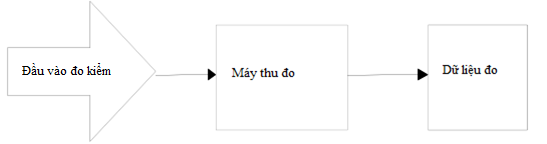
Figure 1 - Test setup to measure the allowed operating frequency range
2.4.6.2.2. Measurement of operating frequency range of the device with a spectrum analyzer
The test antenna must be located at an established point. In addition, a probe can be used
+ Starting frequency: lower than the lower limit of the allowed frequency range.
+ Ending frequency: higher than the upper limit of the allowed frequency range.
+ Resolution bandwidth: see the measuring receiver table at 2.3.6.
+ Video bandwidth: ≥ resolution bandwidth
+ Detector mode: RMS
+ Display mode: Max hold
The 99% occupied bandwidth (OBW) function is used to determine the operating frequency range:
• Determine fH: to be the frequency of the upper marker from the operating frequency range (OFR).
• Determine fL: to be the frequency of the lower marker from the operating frequency range (OFR).
• Determine the central frequency fc: fc = (fH +fL)/2
Alternatively, the results recorded from H field measurement described in 2.4.2.2 may be used.
2.4.6.3. Limits
2
2.4.3.
The operating frequency ranges with targeted emissions must be completely within Table 1 of the corrected range.
2.4.7. Modulation bandwidth
Transmitter’s modulation bandwidth requirements are applied to all product types.
2.4.7.1. Definition
2.4.4.
2.4.4.1.
The modulation bandwidth and associated subbands must be above the following levels:
a) For carrier frequencies below 135 kHz:
- Lower than 23 dB compared with the corresponding carrier level or spurious emission limit, for RFID within the transmitter’s emission boundary of Figure G.1, and for RFID and EAS systems in the transmitter mask of Figures G.2, G.3 and G.4, see CISPR 16-1-4 or the corresponding spurious emission limits determined at 2.4.8, 2.4.9, 2.4.10;
b) For carrier frequencies in 135 kHz to 30 MHz range:
- Lower than 15 dB compared to carrier level or corresponding spurious emission limit, see at 2.4.8, 2.4.9, 2.4.10.
2.4.7.2. Test method
Measurements are made under conditions declared by the manufacturer. The interpretation of measurement results with measurement uncertainty must be given in 2.6.
The transmitter is connected to an artificial antenna or, if the transmitter has an integral antenna, a test coupler is used (see 2.3.3). The RF output of the equipment must be connected to a spectrum analyzer via a 50 variable attenuator.
The transmitter operates with rated carrier power level or measured field strength under normal test conditions. Adjust the attenuation for a consistent level display on the spectrum analyzer.
The transmitter must be modulated with the standard test modulation process (see 2.3.1.2 and 2.3.1.3). If the device has no external modulation, use internal modulation.
For transmitters using a continuous broadband scanning carrier, measurements must be made in scanning mode.
The transmitter output, with or without a test coupler, must be measured using a spectrum analyzer with a suitable resolution bandwidth to accept all major sidebands. Then calibrate the power level of the spectrum analyzer against the power level or field strength measured in accordance with 2.4.7. Calculate the absolute power level of the sideband.
Spectrum analyzer aperture must be enough wide to accommodate the carrier and all major sidebands.
The frequency at points above and below the power envelope during modulation, including frequency drift, to be displayed, must be equal to the levels specified in 2.4.7 recorded as the modulation bandwidth.
2.4.7.3. Limits
2.4.5.
The allowed range of the modulation bandwidth must be within the assigned band, see Table 1, or ± 7.5% of the carrier frequency, whichever is less. For RFID and EAS systems, the allowed modulation bandwidth must be within the transmitter emission boundary in Appendix G (Figures G.1, G.2, G.3 and G.4).
The allowed modulation bandwidth must be within the limits of the assigned frequency band according to Recommendation CEPT/ERC/REC 70-03 or ERC guidelines.
2.4.8. Transmitter’s conductive spurious emission
The transmitter’s conductive spurious emission requirements are applied only to type 3 products.
2.4.8.1. Definition
Spurious emissions are emissions at frequencies other than those of the carrier and sidebands associated with normal test modulation.
2.4.8.2. Transmitter’s conductive spurious emission test method (< 30 MHz)
The transmitter is connected to an artificial antenna as in 2.3.2.1. The measuring receiver, connected to the output of the artificial antenna, measures the carrier current and spurious emission components. Details of the artificial antenna are given in Appendix D.
The method of determining spurious emission current limit Is, is calculated as follows:
Ic Is Hc Hs
Where:
Is is the measured conductive spurious emission current in dBA;
Ic is the measured carrier current in dBA, see 2.4.3.3;
Hc is H field limit emitted in dBA/m, see 2.4.2.3;
Hs is the limit for H field spurious emissions in dBA/m, see 2.4.9.3.
Term Hc Hs in the above formula is the required loss of the H field spurious emission, calculated in dBc.
This requirement may vary with frequency because the limit values vary with frequency.
Term Ic Is, in dB, is the loss of spurious emission current compared to carrier current.
2.4.8.3. Transmitter’s conductive spurious emission test method (≥ 30 MHz)
The transmitter is connected to an artificial antenna according to 2.3.2.2. The spurious emission components are measured with a selective voltmeter connected to the output of the transmitter by a suitable coupling device. Details of the artificial antenna are given in Appendix D.
2.4.8.4. Limits
Limit Is is determined by the formula:
Ic Is = Hc Hs
Where: Hc (see 2.4.2);
Hs (see 2.4.3);
Ic (see 4.3.5).
2.4.9. Transmitter’s radiated domain spurious emissions (< 30 MHz)
The requirements for transmitter radiated domain spurious emissions (< 30 MHz) are applied to all product types.
2.4.9.1. Definition
The radiated domain spurious emission limit is the emission limit at frequencies other than the carrier frequency and sidebands (see 2.4.6 and 2.4.7) accompanied by normal test modulation.
2.4.9.2. Test method
Measurements are made under conditions declared by the manufacturer. The interpretation of measurement results with measurement uncertainty must be given in 2.6.
Field strength must be measured for frequencies below 30 MHz. The equipment under test must be measured at a distance of 10 m at the open-area test site. The test antenna must be a calibrated shielded magnetic field antenna. Arrange equipment under test and test antenna as in A.1 of Appendix A.
For type 3 products, the artificial antenna must be connected to the transmit antenna port of the equipment under test (see 2.3.2) and the output of the artificial antenna must be terminated.
The equipment under test operates with normal modulation. The characteristics of the used modulated signal must be stated in the test report. The measuring receiver must be tuned in 9 kHz to 30 MHz range, excluding the frequency range of the operating transmitter.
At each frequency at which spurious emissions are detected, the equipment under test and the antenna are rotated until the maximum field strength level on the measuring receiver is obtained. This level must be recorded.
If the transmitter can operate in the standby mode, this measurement must be repeated in the standby mode as well.
For instruments calibrated in dBV/m, the measured value must be subtracted by 51.5 dB to obtain the measured value in dB A/m.
2.4.9.3. Limits
Radiations below 30 MHz must not exceed the value of field strength H (dBA/m) at a distance of 10 m, as specified in Table 7.
Table 7 – Transmitter‘s radiated domain spurious emission limit (<30 MHz)
Transmitter status | 9 kHz ≤ f < 10 MHz frequency | 10 MHz ≤ f <30 MHz frequency |
Transmit | 27 dBA/m at 9 kHz descending 3 dB/oct | -3,5 dBA/m |
Standby | 5.5 dBA/m at 9 kHz descending 3 dB/oct | -25 dBA/m |
2.4.10. Transmitter’s radiated domain spurious emissions (> 30 MHz)
The requirements for transmitter’s radiated domain spurious emissions (> 30 MHz) are applied to all product types.
2.4.10.1. Definition
Spurious emissions are emissions at frequencies other than those of the carrier and sidebands associated with normal test modulation.
2.4.10.2. Test method
For class 1, class 2 and class 4 products a suitable test position shall be selected in accordance with Annex A. The equipment to be tested shall be placed on a non-conductive support at a specified height and in a position as close to the normal operating position as declared by the manufacturer.
For type 3 products, connect the artificial antenna to the transmitter antenna port (see 2.3.2).
The test antenna is oriented to have vertical polarization. The output of the test antenna is connected to the measuring receiver.
The transmitter operates in the normal modulation mode and the measuring receiver is tuned in 30 MHz to 1 000 MHz frequency range.
At each frequency at which spurious emitted signals are detected, the test antenna is raised and lowered within the specified altitude until a maximum signal level is obtained on the measuring receiver.
Then, the transmitter is rotated in the horizontal plane, until the maximum signal level on the measuring receiver is reached.
Record the maximum signal level received by the measuring receiver.
The replacement antenna must be directed for vertical polarization and calibrated to the frequency of the detected spurious emission component.
Tune the signal frequency of the standard signal transmitter to the frequency of the detected spurious component. If necessary, tune the input attenuation of the measuring receiver to increase measuring receiver’s sensitivity.
The test antenna is raised and lowered within a specified range to ensure maximum signal reception.
When using a test site in accordance with A.1.1, there is no need to change the antenna height.
The replacement antenna input signal is tuned until the measuring receiver achieves a known equivalent or corresponding level separated from the transmitter.
Record the replacement antenna input signal power level.
The effective radiated power measurement of spurious emission components is the larger of two power levels recorded for each spurious emission component at the replacement antenna input.
If an unmodulated carrier is not available, measurements must be made with the normal test signal (see 2.3.1.3). In this case, this must be recorded in the test report.
If the transmitter has a standby mode, take measurements in the standby mode as well.
2.4.10.3. Limits
Any spurious radiated power must not exceed the values specified in Table 8.
Table 8 – Transmitter’s radiated domain spurious emission limit (> 30MHz)
Status | Frequency | Other frequencies between 30 MHz and 1 000 MHz |
From 47 MHz ÷ 74 MHz From 87.5 MHz ÷ 118 MHz From 174 MHz ÷ 230 MHz From 470 MHz ÷ 790 MHz | ||
Operating | 4 nW | 250 nW |
Standby | 2 nW | 2 nW |
2.4.11. Transmitter’s frequency stability
2.4.1.11. Definition
Frequency stability under low voltage conditions is the ability of the device to maintain its operating frequency and not produce emissions beyond any relevant limit when the battery voltage drops below the ultra-low voltage.
Frequency stability is applied only to multiplexing systems where channel limits are defined.
2.4.1.12. Test method
Measurements are made under conditions declared by the manufacturer. The interpretation of measurement results with measurement uncertainty must be given in 2.6.
Step 1:
The equipment is in operation mode at the operating frequency declared by the manufacturer, with the appropriate test signal and the equipment is operated at the rated operating voltage.
The center frequency of the transmitted signal must be measured and recorded.
Step 2:
The operating voltage must be reduced in appropriate steps until the voltage is zero.
The center frequency of the transmitted signal must be measured and recorded.
Any unusual information should be noted.
2.4.11.3. Limits
The equipment must meet one of the following conditions:
a) Remain within the operating channel without exceeding any acceptable limit (e.g. duty cycle); or
b) Reduce the effective radiated power below the spurious emission limits without exceeding any applicable limit (e.g. duty cycle); or
c) off, (e.g. no emission above EMC level).
2.5. Requirements for receiver
2.5.1. Adjacent channel selectivity
This measurement is only required when using frequency planning with standard channel spacing, for example at 27 MHz.
Not perform this measurement if:
a) The transmitter cannot be switched off and the distance between the transmitter and receiver frequencies is 10 times less than the declared 3 dB bandwidth; or
b) The transmitter and receiver operate on the same frequency and the transmitter cannot be switched off because the carrier is used as the input signal to the receiver (for example for homodyne systems).
In case a) and/or b) items above are applied, this must be recorded in the test report.
This requirement is not applied to tagging systems (Ex: RF identification, anti-theft, access control, positioning system).
The adjacent channel selectivity for the receiver is applied only to demultiplexing systems
2.5.1.1. Definition
Adjacent channel selectivity is a measure of the receiver's ability to operate in the presence of an unwanted signal with frequency differing from that of the wanted signal by an amount equal to the adjacent channel spacing.
2.5.1.2. Test method
2
2.5.1.1.
2.5.1.2.
Measurements are made under normal conditions. This measurement is applied only to demultiplexers.
Two signal transmitters A and B are connected to the receiver via a combined network, or:
a) Through the test coupler or test antenna to a receiver with an integral, dedicated or test antenna; or
b) Directly to the temporary or permanent antenna port of the receiver.
The method of connection to the receiver is recorded in the test report.
Signal transmitter A is located at the nominal frequency of the receiver, with normal modulation process of the wanted signal.
Signal transmitter B is unmodulated and must be tuned to the adjacent channel frequency immediately above the wanted signal frequency channel.
Initially, signal transmitter B is switched off and signal transmitter A is used with the signal level making a sufficient response. Then increase the signal transmit level by 3 dB.
Turn on signal transmitter B and tune the signal level until the desired target is reached. Record this level.
The measurement is repeated with transmitter signal B tuned to the adjacent channel frequency immediately below the wanted signal.
The adjacent channel selectivity for the upper and lower channels is the ratio in dB of the unwanted signal level to the wanted signal level.
2.5.1.3. Limits
Adjacent channel selectivity of the equipment in the specific conditions is not less than the value specified in Table 9.
Table 9 - Adjacent channel selectivity
Channel spacing | Channel spacing |
60 dB | 70 dB |
2.5.2. Intercept characteristics or reduction of reception sensitivity to unwanted signals
2.5.2.1. Definition
Intercept ability (reduced receiving sensitivity to unwanted signals) is the receiver’s ability to receive a wanted modulated signal without causing a degradation in quality beyond a specified level due to the presence of the unwanted input signal at any frequency regardless of spurious responses or adjacent channel selectivity, see 2.5.1.
This requirement is not applied to tagging systems (Example: RF Identification, devices using NFC near-field communication technology, Smart Card, anti-theft, access control, positioning system, etc.)
2.5.2.2. Test method
Measurement is made under normal conditions.
Two signal transmitters A and B are connected to the receiver via a combined network or:
a) Through the test coupler or test antenna to receiver with integral antenna or dedicated antenna; or
b) Directly to the temporary or permanent antenna port of the receiver.
The method of connection to the receiver is recorded in the test report.
Signal transmitter A is set to the nominal frequency of the receiver, with normal modulation process.
Signal transmitter B is unmodulated and tuned to the test frequency specified below.
Initially, signal transmitter B is switched off and signal transmitter A is used with a signal level corresponding to the specified receiver sensitivity. Then signal transmitter A increases by 3 dB.
Turn on signal transmitter B and tune the signal level until the desired target is reached. Record this level.
The frequency of signal transmitter B is determined by a) or b), whichever is greater, as follows:
a) For frequency range from 9 kHz to < 500 kHz, measurements made at the adjacent frequencies +50 kHz, +100 kHz, +200 kHz, +300 kHz and +500 kHz from the receiver's highest operating frequency plus the receiver's 3 dB bandwidth.
Repeat the measurements at adjacent frequencies of -50 kHz, -100 kHz, -200kHz, -300 kHz and -500 kHz from the receiver's lowest operating frequency minus the receiver's 3 dB bandwidth.
For frequency range ³ 500 kHz to 30 MHz, measurements made at frequencies adjacent to +500 kHz, +1 MHz, +2 MHz and +5 MHz from the receiver's highest operating frequency plus the receiver's 3 dB bandwidth.
The measurements must be repeated at the adjacent frequencies of -500 kHz, -1 MHz, -2 MHz and -5 MHz from the receiver's lowest operating frequency minus the receiver's 3 dB bandwidth.
The manufacturer must declare the operating frequencies and 3 dB bandwidth of the receiver;
or:
b) The upper and lower test frequencies for transmitter B are specified as follows:
Upper test frequencies: highest operating frequency + (receiver’s 3 dB bandwidth) (NB + 1).
Lower test frequencies: lowest operating frequency - (receiver’s 3 dB bandwidth) (NB + 1).
The value of NB is specified in 2.5.2.3, Table 10.
The manufacturer must declare the operating frequencies and 3 dB bandwidth of the receiver.
For systems with scanning operating frequencies:
Upper test frequencies: highest operating frequency + (receiver’s 3 dB bandwidth) (NB + 1).
Lower test frequencies: lowest operating frequency - (receiver’s 3 dB bandwidth) (NB + 1).
The manufacturer must declare the operating frequencies and bandwidth of 3 dB and the scanning range of the receiver.
The ability to intercept or reduce unwanted signal reception sensitivity is the ratio in dB, of the lowest level of the unwanted signal (transmitter B) with the wanted signal level (transmitter A).
Not specify and not measure transmitter B’s frequencies below 9 kHz
2.5.2.3 Limits
The intercept ratio for any frequency in the specified ranges must not be less than the values specified in Table 10, except for frequencies where spurious emission responses are present. The limit value is determined by the reference limit value (Ref) plus the correction factor (dB) depending on the respective receiver classification.
Table 10 – Ability to reduce reception sensitivity to unwanted signals
Transmitter’s frequency shift B fA fB according to a) or b), whichever is greater (see note 3) | Limit (dB) | ||
a) according to item 2.5.2.2 clause a) | b) according to section 2.5.2.2, clause b) | ||
fA 500 kHz | fA 500 kHz | Value of NB, see below |
|
100 kHz | 500 kHz | 2 | Reference limit 1/2 (see note 2) |
200 kHz | 1 MHz | 4 | Reference limit 2/3 (see note 2) |
300 kHz | 2 MHz | 8 | Reference limit 5/6 (see note 2) |
500 kHz | 5 MHz | 20 | Reference limit (see note 1) |
NOTE 1: Reference limit (Ref) = 30 dB at 9 kHz increases with a slope of 10 dB/decade to 65.2 dB at 30 MHz. Note 2: The limit is a fraction of the standard value. NOTE 3: Transmitter B frequencies below 9 kHz are not specified. | |||
2.5. 3. Receiver’s spurious emissions
This requirement is not applied to receivers used in conjunction with co-located fixed transmitters for continuous transmission. In these cases, the receiver must be tested with the transmitter in active mode (see 2.4.7).
2.5.3.1. Definition
Spurious emissions from the receiver are radiated from antenna, chassis and receiver housing, defined as the radiated power of the discrete signal.
2.5.3.2. Test method
1) For radiations below 30 MHz, the test method must be in accordance with 2.4.9.2.
2) For radiations equal to or above 30 MHz, the test method must be in accordance with 2.4.10.2.
Convert the measurement by a factor of 51.5 dB for measuring device calibrated in dBV or dBV/m.
2.5.3.3. Limits
2.5.3.3.3.1. Radiated emissions below 30 MHz
Spurious emissions below 30 MHz must not exceed H field strength values (dBA/m) at a distance of 10 m, specified in Table 11.
Table 11 – Receiver‘s spurious emission limits
9 kHz ≤ f < 10 MHz frequency | 10 MHz ≤ f < 30 MHz frequency |
5.5 dBA/m at 9 kHz descending 3 dB/oct | -25 dBA/m |
2.5.3.3.2. Radiated emissions above 30 MHz
The measured value does not exceed 2 nW.
2.6. Measurement uncertainty
The interpretation of results recorded in a test report for the measurements described in this document must be as follows:
- The measured value related to the respective limit must be used to decide whether an equipment meets the requirements of this regulation;
- The value of the uncertainty for the measurement of each parameter must be included in the test report;
- The recorded value of the measurement uncertainty must be, for each measurement, equal to or less than the figures in Table 12.
Table 12 — Maximum measurement uncertainty
No. | Parameters | Measurement uncertainty |
1 | Radio frequency | ±1 x 10⁻⁷ |
2 | RF Power (conductive) | ±1 dB |
3 | RF power (radiated) | ±6 dB |
4 | Temperature | ±1 0 C |
5 | Humidity | ±5 % |
For test methods, according to this regulation, the measurement uncertainty data must be calculated according to the method described in ETSI TR 100 028 and will correspond to the coefficient of expansion (coverage factor) k = 1.96 or k = 2 (providing 95% and 95.45% confidence levels, respectively, in case the distributions representing actual uncertainty are normal (Gauss)).
The uncertainty in Table 12 is based on such extensible factors.
The specific expansion factor used to evaluate the measurement uncertainty must be clearly stated.
3. PROVISIONS ON MANAGEMENT
3.1. Short range devices in 9 kHz -25 MHz frequency range and magnetic loop equipment operating in 9 kHz to 30 MHz frequency range within the governing scope in section 1.1 must comply with the technical regulations in this regulation.
3.2. Operating frequency of the device: comply with regulations on management and use of radio frequencies in Vietnam.
3.3. Measuring equipment and devices: comply with current regulations of the law on measurement.
4. RESPONSIBILITIES OF ORGANIZATIONS AND INDIVIDUALS
Relevant organizations and individuals are responsible for implementing regulations on conformity certification and conformity declaration for short-range radio equipment in the frequency range from 9 kHz to 25 MHz and magnetic loop equipment operating in the frequency range from 9 kHz to 30 MHz according to regulations on conformity certification and conformity declaration and are subject to inspection by state management agencies according to current regulations.
5. ORGANIZATION OF IMPLEMENTATION
5.1. The Vietnam Telecommunications Authority, the Authority of Radio Frequency Management and the Departments of Information and Communications are responsible for organizing the implementation of instructions and management of short range device in 9 kHz -25 MHz frequency range and magnetic loop equipment operating in 9 kHz to 30 MHz frequency range according to this Regulation.
5.2. This regulation is applied to replace the National Technical Regulation QCVN 55:2011/BTTTT “National technical regulation on short range device – radio equipment to be used in the 9 kHz - 25 MHz frequency range”.
5.3. In case the provisions mentioned in this regulation are changed, supplemented or replaced, the provisions of the new document must be applied.
5.4. In the process of implementing this regulation, if there is any problem or entanglement, relevant organizations and individuals must report in writing to the Ministry of Information and Communications (Department of Science and Technology) for guidance and settlement.
Appendix A
(Normative)
Radiation measurement
A.1. Test sites and general arrangement for measurements related to use of radiated fields
This appendix introduces three most common test sites that can currently be used for radiation testing, including: absorption chamber, semi-absorption chamber (absorption chamber with a grounded bottom) and open-area test site (OATS). In general, these test sites are referred to as free-field test sites. Both absolute and relative measurements can be made at these sites. To make absolute measurements, inspection of the measuring chamber is required. Detailed inspection procedures are described in ETSI TR 102 273-2, ETSI TR 102 273-3 and ETSI TR 102 273-4.
NOTE To ensure that the radiation measurements can be easily controlled and reproduced, use these test sites only for the measurements in this Regulation.
A.1.1. Absorption chamber
Absorption chamber is a shielded enclosed space in which the interior of the walls, floor and ceiling of the chamber is covered with a radio- absorbing material, usually a pyramidal urethane foam. Typically, the chamber consists of an antenna holder at one end and a turntable at the other. A typical absorption chamber is illustrated in Figure A.1.

![]()
![]()
![]()
![]()
![]()
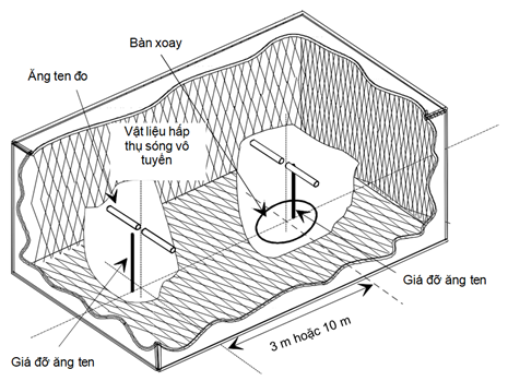
Figure A.1 - Typical absorption chamber
The use of radio-absorbing materials in combination with chamber shielding will create a controlled environment for test purposes. This type of chamber best simulates free space conditions.
The shielding will create a test space that reduces the interference of the surrounding signals and also reduces other external effects, while the radio-absorbing material will reduce the unwanted reflective rays from walls and ceilings, which may affect the measurement. In fact, it is easy to shield to eliminate high-level ambient noise (80 dB to 140 dB), which can often be ignored.
The turntable must rotate 3600 in the horizontal plane and is used to raise the sample of equipment under test (EUT) to a suitable height from the floor (e.g. 1 m). The measuring chamber must be large enough that the measuring distance must be at least 3 m or 2 (d1 + d1)2/λ (m), whichever is the largest of these two values (see A.2.4). The actual measured distance must be recorded with the measurement results.
Absorption chamber generally have several advantages over other test facilities. It minimizes ambient interference, minimizes reflections from floors, ceilings, walls and is weather independent. However, absorption chamber has several disadvantages including measuring distance and limited use of lower frequencies due to the size of pyramidal absorption materials. To improve low-frequency performance, a combination of ferrite tips with urethane foam absorption layers is often used.
All radiation, sensitivity and immunity measurements can be performed in the absorption chamber without any restriction.
A.1.2. Semi-absorption chamber (Absorption chamber with conductive bottom side)
A semi-absorption chamber is an absorption chamber with a floor made of uncoated metal and forming the base plane. A typical semi-absorption chamber is described in Figure A.2.
The semi-absorption chamber simulates an ideal open-area test site with main feature that is a perfect conductive base plane that extends indefinitely.


![]()
![]()
![]()
![]()
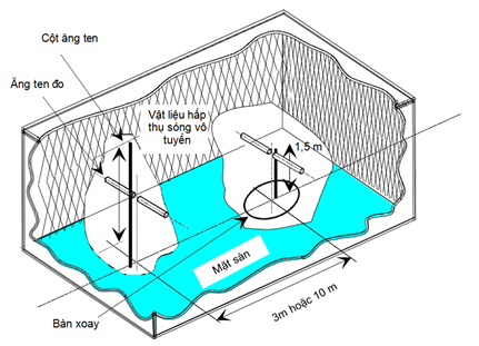
Figure A.2 - Typical semi-absorption chamber
In this chamber, the bottom side produces the desired reflective ray, so that the received signal at the receiving antenna will be the sum of the signals transmitted in a straight line and along a reflected path. Thus, for each given height of the transmitting antenna (or EUT) and the receiving antenna above the floor, we will have unique received signal level.
The antenna mast has a variable height of 1 m to 4 m so that the position of the test antenna can be optimized for maximum coupling signal between antennas or between the EUT and the test antenna.
A turntable is capable of rotating 360° in a horizontal plane and used to raise the sample of equipment under test (EUT) to a certain height above the floor, usually 1.5 m. The measuring chamber must be large enough so that the minimum distance is 3 m or 2(d1 + d2)2/λ (m), whichever is the largest of these two values (see A.2.4). The actual measured distance must be recorded with the measurement results.
Emission measurement is primarily the measurement of the maximum field strength value radiated from the EUT by adjusting the height of the receiving antenna on the mast (to receive amplitude plus interferences of the direct and reflected signals from the EUT), then rotate the turntable to find the direction to receive the maximum field strength in the azimuth plane. The amplitude value of the received signal at this height of the test antenna must be recorded. Secondly, replace the EUT with a replacement antenna (located at the center of mass or the center of the EUT), which is connected to a signal transmitter. 'Maximize' the field strength value of the signal emitted by this replacement antenna, the transmitter output must be adjusted to exactly the value recorded in step one.
Receiver sensitivity measurements over a ground plane are also to 'maximize' the field strength by adjusting the height of the test antenna on the mast to obtain amplitude plus interferences of the signal according to a straight line and the reflection path is the highest, this time place the test antenna at the correct position of the center of mass or the center of the EUT for testing. There must be a conversion factor here. The test antenna remains at the same height as step two, while the test antenna is replaced by the EUT. Reduce the amplitude of the transmitted signal to determine the field strength level at which the specified response of the EUT is maintained.
A.1.3. Open-area test site (OATS)
A.1.3.0. General
OATS can be used for measurements in 9 kHz to 1 000 MHz frequency range.
Measurements below 30 MHz must be carried out in accordance with A.1.3.1 and measurements above 30 MHz must be made in accordance with A.1.3.2.
The open-area test site consists of a turntable at one end and a variable height antenna mast at the other. A typical OATS is depicted in Figure A.3.
In Figure A.3, for measurements below 30 MHz, the dipole antennas must be replaced by loop antennas and as explained in A1.3.1.
![]()
![]()
![]()
![]()
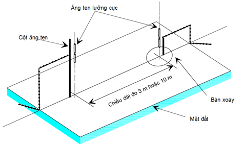
Figure A. 3 – Typical open-area test site
A.1.3.1. Measurements below 30 MHz
For measurements below 30 MHz, measurements can be performed according to CISPR 16-1-4. Measurements are made using a shielded inductive loop test antenna, which reads only the magnetic field (H field). These measurements are valid for both far and near fields. In this case, the OATS must not have a ground of conductive or magnetic material.
For radiated emission test site (OATS) below 30 MHz, there must be no metal objects, buried pipelines and any objects that could affect the radiation measurement. An alternative test site that proves to be equivalent to a test site as described in the preceding section will be accepted for the purposes of this regulation.
A.1.3.2. Measurements above 30 MHz
The open-area test site consists of a turntable at one end and a variable height antenna mast at the other end. The ground surface in the ideal case is perfectly conductive and expands infinitely. In fact, it is possible to create a good conductive base plane, but it is not possible to create an infinite base plane. A typical OATS is depicted in Figure A.3.
The base plane produces the desired reflective rays, so the receiving antenna will receive a signal that is the sum of the transmitted signal and the reflected signal. For each transmitting antenna (or EUT) height and receiving antenna height above the ground, the phase difference between these two signals will produce a single receipt level.
The quality of the test site is related to antenna positions, turntables, measuring distances and other arrangements such as semi-absorption chambers. In radiation measurements, the open-area test site is used similar to the semi-absorption chamber.
The most common arrangement for a test site with a base plane to measure spurious emissions is depicted in Figure A.4.


![]()
![]()
![]()
![]()
![]()
![]()
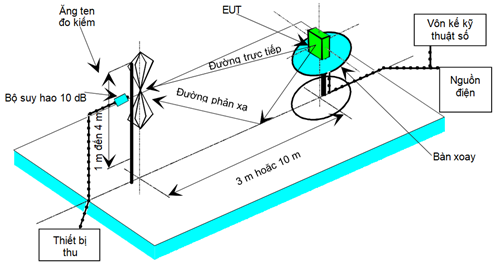
Figure A.4 — Measurement arrangement at test site with conductive base plane
(Set up OATS for spurious emission testing)
A.1.4. Test antenna
The test antenna is always used in radiation measurement methods. For emission measurements (i.e. frequency error, effective radiated power, spurious radiated power and adjacent channel power), the test antenna is used to receive the radiated field strength from EUT in step one of the measurement procedure, and receive the radiated field strength from the replacement antenna in step two. When the test site is used to measure the receiver characteristics (i.e. different sensitivity and immunity parameters), the test antenna is used as a transmitter.
The test antenna must be mounted on a support that allows the antenna to be used in either vertical or horizontal polarization, and in test sites with a base plane (i.e. semi-absorption or open-area test sites), the height of the antenna center above the ground must be variable within a certain range (usually 1 m to 4 m).
In 9 kHz to 30 MHz frequency range, the inductive loop antenna is shielded according to CISPR 16-1-4 commonly recommended for use. This test antenna method supports measurements in both far and near field.
In 30 MHz to 1 000 MHz frequency range, dipole antennas (structure corresponding to ANSI C63.5) are recommended. For frequencies equal to or greater than 80 MHz, the dipole antennas must be of such rod length that there is resonance at the test frequency. For frequencies less than 80 MHz, it is recommended to use dipole antennas with short rod length. However, for spurious emission measurements, a combination of bicones and logarithmic dipole antennas should be used (commonly referred to as periodic logarithmic antennas) to be able to work in both frequency ranges from 30 MHz to 1 000 MHz. For frequencies above 1 000 MHz, loudspeaker waveguides are recommended, although in this case periodic logarithmic antennas can still be used.
NOTE: The gain of a loudspeaker antenna is usually expressed as equivalent to an isotropic emitter.
A.1.5. Replacement antenna
The replacement antenna is used as a substitute for the EUT in transmitter’s parameter measurements (i.e. frequency error, effective radiated power, spurious reflections and adjacent channel power). For measurements made in 30 MHz to 1 000 MHz frequency range, the replacement antenna must be a dipole antenna (structure in accordance with ANSI C63.5). For frequencies greater than or equal to 80 MHz, the dipole antennas must be of such rod length that they are resonant at the test frequency. For frequencies less than 80 MHz, it is recommended to use dipole antennas with short rod length. For frequencies above 1 000 MHz, loudspeaker waveguides should be used. The center of this antenna must coincide with the EUT electrical or mass center.
Alternative measurements below 30 MHz are not used because the radiated H field is measured with a shielded loop antenna according to CISPR 16-1-4.
A.1.6. Measuring antenna
The measuring antenna is used in measurements on the EUT to measure the receive parameter (i.e. measure the sensitivity and measure the anti-interference parameters). The purpose of this type of antenna is to allow electric field strength in the region adjacent to the EUT.
For measurements in 30 MHz to 1 000 MHz frequency range, the measuring antenna must be a dipole antenna (structure in accordance with ANSI C63.5). For frequencies greater than or equal to 80 MHz, the dipole antennas must be of such rod length that they are resonant at the test frequency. For frequencies less than 80 MHz, it is recommended to use dipole antennas with short rod length. The center of the measuring antenna must coincide with the EUT's facial center mass center (as specified in the test method).
For measurements on inductive loop systems operating below 30 MHz, the test antenna must be a calibrated loop antenna.
A.2. Instructions for use of radiation test sites
A.2.0. General
This section details the procedures, check and arrangement of and test equipment must be performed prior to any radiation measurement. This is common regulation to all test sites as specified in A.1.
A.2.1. Check of test site
No measurement must be made at a test site before this site has been confirmed as tested. Test procedures for the different types of test sites specified in A.1 (i.e. absorption chamber, semi-absorption chamber and open-area test site) are also specified in ETSI TR 102 273-2, ETSI TR 102 273-3 and E ETSI TR 102 273-4, corresponding to A.2.2, A.2.3 and A.2.4.
A.2.2. Preparation of EUT
The manufacturer must provide information about the EUT including: operating frequency, polarization, supply voltage and external structure. Additional, specific information about the EUT such as carrier power, channel spacing, whether this sample can work in different modes (e.g. high and low power modes), work in continuous mode or there are some maximum test cycles (e.g. one minute on, four minutes off).
If necessary, a holder with the smallest dimensions must be provided to place the EUT on the turntable. This holder must be made of a low conductive material with a relatively low dielectric constant (i.e. less than 1.5) such as shrink-resistant polystyrene, balsa wood, etc.
A.2.3. Power supply for EUT
Where possible, all measurements must be powered on when measurements are made, including measurements carried out on EUTs designed to use only batteries. In all cases, the power supply conductor must be connected to the EUT power supply terminal (and checked with a digital voltmeter), however the battery must be retained but the battery must be completely insulated from the equipment, this can be done by wrapping tape around the battery contacts.
However, the presence of power supply conductors also affects the measurement performance of the EUT. They should therefore be made in a manner as “transparent” in terms of testing as possible. This can be done by placing the power supply conductors away from the EUT and under the shield, under the base plane or behind the walls of the equipment (as applicable) in the shortest path. Great care must be taken to avoid sensing between conductors (e.g. conductors may be twisted together, loaded with ferrites spaced 0.15 m apart, or another type of load).
A.2.4. Measuring distance
A.2.4.1. Far-field measuring distance over 30 MHz
The measuring distance of all types of equipment must ensure that the measurement is made in the far field of the EUT, i.e. the distance must be greater than or equal to:
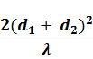
Where:
d1: is the maximum size of EUT/ Dipole antenna after replacement (m);
d2: is the maximum size of the test antenna (m);
![]() : is the wavelength of the test frequency (m).
: is the wavelength of the test frequency (m).
Note: if at the replacement part of the measurement, both the test antenna and the replacement antenna are half-wave dipole antennas, the minimum distance of the far-field measurement must be:
![]()
Note: in test results when either of these conditions is not met, the measurement uncertainty must be added to the measurement result.
NOTE 1: For a fully absorbing chamber, at any angle of rotation of the turntable, no part of the EUT must be outside the “quiet zone” of the measuring chamber at the rated frequency of measurement.
Note 2: The “quiet zone” is the volume contained in the absorption chamber (the type of chamber without a grounded surface) which is either proven by measurement or guaranteed by the designer/manufacturer to have an effective definite measure. Usually, the measurement efficiency is determined either by the reflectance of the absorbing plates or as a directly related parameter (e.g. signal amplitude and phase uniformity). Note, however, that definitions of “quiet zone” tend to change.
Note 3: For absorption chamber with one grounded surface: there must be sufficient scanning capability in height, i.e. from 1 m to 4 m, so that neither part of two types of absorption chamber, reflectance of the absorbing panels must not be less than -5 dB.
Note 4: For absorption chambers with grounded surfaces and open-area test sites: at any time during the course of the measurements, no part of any antenna must not be less than 0.25 m from the base plane. When one of these conditions is not satisfied, no measurement must be made.
A.2.4.2. Near field and far field measurement distance less than 30 MHz
Inductive systems below 30 MHz can be measured both in the near field and in the far field at the open-area test site using a shielded loop antenna according to CISPR 16-1-4.
The minimum measuring distance, d, is determined by:
d ≥ 3D
where D is the largest dimension in meter of the inductive conductor loop.
A.2.5. Preparation of test site
Conductors at two ends of the test site must be horizontal at least 2 m away from the test site in the horizontal plane (unless both types of absorption chambers have back retaining walls) and then allowed to down-wire and through the base plane or barrier (as the case may be) to reach the test equipment. Care must be taken when wiring to minimize sensing between conductors (e.g. ferrite beads or other resistors must be covered). The wiring and sheathing of the cables must be the same as during the test.
NOTE: For base plane reflectance measurement sites (i.e., semi-absorption chambers and open-air test sites) where a combination of a cable duct and an antenna mast is required, the 2 m requirement is impossible. In this case, the routing of the conductors must be described in the test report.
Correction data for all components of the test equipment should be available and valid. For test, test antennas and replacement antennas, the data must include a gain factor related to the isotropic radiation factor (or antenna factor) at the test frequency. Similarly, the VSWR values of the replacement and test antennas must be included.
Correction data for all conductors and attenuators must include additional loss and VSWR over the entire frequency range of the measurements. All VSWR and additional attenuation values must be recorded on the log result page for the particular test.
Correction coefficients/tables should be available as needed.
For all components of the test equipment, the maximum errors together with their distribution must be known, for example:
- Cable loss: ±0.5 dB with rectangular distribution;
- The measuring receiver: the signal level accuracy is 1.0 dB (standard deviation) with a Gaussian error distribution.
At the beginning of the measurements, a systematic check must be performed on all measured components of the equipment used at the measuring site.
A.3. Signal coupling
A.3.1. General
Conductors in a radiated field can interfere with that radiated field and lead to measurement uncertainty. Interference effects can be minimized by using suitable coupling methods, ensuring signal isolation and minimizing interference effects on the radiated field (e.g. acoustic and optical coupling)
A.3.2. Data signal
Signal isolation can be done using optical, ultrasonic or infrared devices. The radiated field interference can be minimized by using a suitable optical fiber link. Ultrasonic or infrared connections require proper measurement to minimize ambient noise.
A.4. Standard test site
Except for the electric field transmitter, the standard test site within all test sites for non-wearable equipment, including portable equipment, must be a non-conductive, high 1.5 m, capable of rotating around the vertical axis of the device. The standard test site of the equipment must be as follows:
a) For equipment with an integral antenna, it must be located in the position closest to the most commonly used position declared by the manufacturer.
b) For equipment with a rigid external antenna, the antenna must be vertical.
c) For equipment with a flexible external antenna, the antenna must be erected by an insulated support.
A humanoid stand can be used to measure specialized devices worn on the
body.
This humanoid stand consists of a rotatable acrylic tube filled with saline, placed on the ground.
This pipe must have the following dimensions:
- Height: 1.7 ± 0.1 m;
- Inner diameter: 300 ± 5 mm;
- Thickness of pipe wall: 5 ± 0.5 mm.
The tube is filled with a saline solution (NaCl) with a concentration of 1.5 g/liter of distilled water.
The device must be held in place on the surface of a humanoid support, at the appropriate height of the device.
NOTE: To reduce the weight of the simulator, an alternative form of tube with a hollow core of 220 mm maximum diameter can be used.
In the electric field transmitter, the equipment under test or the replacement antenna must be placed in the test area in the normal operating position, corresponding to the applied field, on a base made of low dielectric material (the dielectric coefficient less than 2).
A.5. Measuring coupler
A.5.0. Use of measuring coupler
For equipment with an integral antenna and without a 50 Ω output terminal, a suitable measuring coupler must be used.
A.5.1. Description
The measuring coupler is a type of radio equipment used to couple the antenna inside the machine to a 50 Ω RF terminal at all frequencies to be tested. This allows certain measurements to be made using conductivity measurement. Only relative measurements are made at or near the frequencies for which the measuring coupler is calibrated.
The measuring couplers must be fully described. In addition, the measuring coupler can provide:
a) Connection to an external power source.
b) A method of providing input or output from the device. This may include coupling to or from the antenna. In case of voice equipment evaluation, the audio interface may be provided either by direct connection or by an audio coupler, or in case of non-speech devices, the test equipment may also provide a suitable means of coupling, e.g. data.
The measuring coupling boxes are usually supplied by the manufacturer.
The performance characteristics of the measuring equipment must be approved by the laboratory and must be subject to the following basic parameters:
a) The coupling loss must not be more than 30 dB;
b) Bandwidth properties are suitable;
c) The variation in coupling loss does not exceed 2 dB over the frequency range used in the measurement;
d) The interconnection circuit to be connected to the RF terminal must be one which must not contain active or non-linear devices;
e) VSWR at the 50 Ω socket must not be greater than 1,5 over the frequency range of the measurements;
f) The coupling loss must be independent of the position of the measuring coupler and unaffected by the proximity of surrounding objects or people. The coupling loss must be reproducible when the test equipment is dissembled and replaced. Normally, the measuring coupler is in a fixed position and specifies the position for the EUT;
g) The coupling loss will not change appreciably when the environmental conditions change.
The measuring coupler specifications and the calibration of the measuring coupler must be recorded in the test report.
A.5.2. Correction
The correction of the measuring coupler determines the relationship between the signal transmitter output and the equipment field strength inside the measuring coupler.
For each specified polarization type, the correction is valid only at a given frequency of the signal transmitter.
In practice, the layout depends on the equipment type (data, voice, etc.).
![]()
![]()
![]()
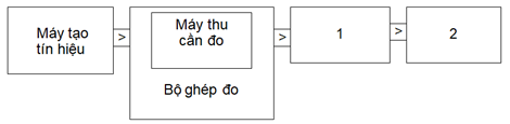
1) Coupling equipment.
2) Technical indicator evaluation equipment, e.g. distortion factor/sound level meter, bit error ratio meter BER, etc.
Figure A.5 – Layout of equipment for correction
Correction method:
a) Determine the sensitivity expressed in intensity as specified in this specification and record the field strength value in dBµV/m and used type of polarization;
b) Place the receiver inside the measuring coupler connected to the signal transmitter. The signal level of the transmitter generates:
- The bit error rate is 0.01; or
- An acceptable message rate of 80% must be recorded.
The measuring coupler correction is the relationship between the field strength in dBµV/m and the signal transmitter signal level in dBµV/m emf. This relationship is considered linear.
A.5.3. Method of execution
The measuring coupler can be used for measurements with equipment having an integral antenna.
In particular, the measuring coupler is used to measure radiated carrier power and sensitivity (expressed as magnetic field strength) under extreme conditions.
For transmitter measurements, no correction is required as relative measurements in use.
For receiver measurements, it is necessary to calibrate as absolute measurements in use.
To apply to a defined wanted signal level expressed as a magnetic field strength, convert this value to the signal transmitter signal level (emf) using a measuring coupler correction. Apply this value to the signal transmitter.
A.6. Technical features of spectrum analyzer
1 kHz resolution bandwidth specification can be used to measure the amplitude of a signal or noise at a level 3 dB or more above the background noise displayed on the spectrum analyzer screen, with an accuracy of ± 2 dB in the presence of a signal at a frequency separation of 10 kHz, at a level 90 dB above the level of the signal to be measured.
Frequency marker reading accuracy must be within ±2% of the secondary frequency range.
The accuracy of the relative amplitude measurements shall be within ±1 dB.
The spectrum analyzer can be adjusted to allow separation of two components with a frequency difference of 1 kHz on the screen.
Appendix B
(Normative)
H field limit correction factor for generated E fields
![]()
![]()
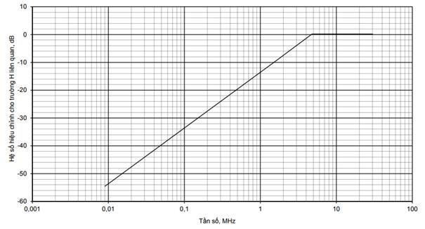
Figure B.1 – H field limit correction factor
Appendix C
(Normative)
Customized loop antennas
C.1. Types of loop antenna-related products
This regulation permits the manufacture of customized loop antennas
with the following limitations:
- Type 1 products are tested with an integrated or separate antenna, no
modification of the customized antenna is allowed;
- Type 2 products are limited to antenna cross-sections less than 30 m2 and loop antenna loop length is less than the smallest value of t two values: l/4 hay 30 m;
- Type 2 products are tested with two loop antennas with the maximum and minimum sizes provided by the manufacturer. Type 2 products allow: customized loop antennas in accordance with the manufacturer's design principles.
- Type 3 products are limited to loop antenna with sizes larger than 30 m2. Only
equipment with an artificial antenna is tested: a large loop change is allowed.
The design formulas given in sections C.2 and C.3 are for guidance only.
C. 2. Antenna loops below 1 MHz
The radiated magnetic H field from an inductive antenna in the near field is defined as:
 Where:
N: number of turns of inductive antenna.
I: current in the antenna's inductor in Ampere.
A: cross-section of the inductor in m2.
d: distance from transmitter, in m.
The above formula is only valid for low frequencies under the following conditions:
• Length of inductor: l < / 2π
• Distance from inductor: d < /2π
The product of NIA is the magnetic dipole moment m of the inductor.
Formula of magnetic moment:
m = NIA = H 2π d3 (Am2) (C.2)
In this technical regulation, the standard measuring distance d is 10 m or 30 m.
If the distance of 10 m is replaced into (C.2), we have:
m = NIA = H10 × 6283 (Am2) (C.3)
Where:
H10 is H field limit at a distance of 10 m in A/m, see 2.4.2.
The above relation is valid only for frequencies up to 1 MHz.
The method of measuring the loop current in the artificial antenna is given in Appendix D.
C.3. Antenna loops above 1 MHz
For frequencies above 1 MHz, the maximum dipole moment can be calculated by the following formula:
![]() (C.4)
(C.4)
Where:
μ0: Magnetic permeability of free space;
m: magnetic moment of dipole antenna;
c: speed of light
f: frequency
The formula (C.4) can be rewritten as:
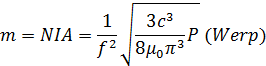 (C.5)
(C.5)
Above 1 MHz, the limit ![]() is determined by formula (C.5) and is reduced by
is determined by formula (C.5) and is reduced by ![]() or 12 dB/oct.
or 12 dB/oct.
Below 1 MHz, the limit ![]() is determined by formula (C.3), see C.2.
is determined by formula (C.3), see C.2.
The relevant e.r.p limits are 250 nW, 2.5 mW and 10 mW.
The products N x I x A are calculated in the formulas (C.6), (C.7) and (C.8), respectively:
With e.r.p = 250 nW e.r.p in (C.5):
![]() (C.6)
(C.6)
With e.r.p = 2.5 mW e.r.p in (C.5):
![]() (C.7)
(C.7)
With e.r.p = 10 mW e.r.p in (C.5):
![]() (C.8)
(C.8)
where ![]() is the frequency in MHz in the formulas (C.6), (C.7) and (C.8).
is the frequency in MHz in the formulas (C.6), (C.7) and (C.8).
The method of measuring the loop current in an artificial antenna is given in Appendix D.
Appendix D
(Informative)
Inductive transmitter’s carrier and harmonic current metering coupler using artificial antenna (applicable to group 3 products only)
An artificial antenna is used for equipment with an antenna terminal and for sample testing without any antenna. The radiated fields of the carrier and spurious emissions are proportional to the RF carrier and spurious emission currents. Therefore, measurements are made to determine the RF carrier and spurious emission currents in the artificial antenna.
![]()
![]()
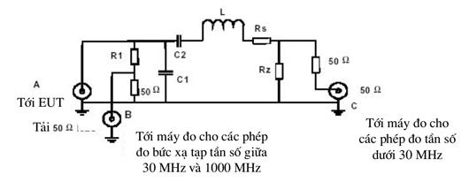
Figure D.1 - Mechanical diagram and equivalent electrical circuit of components
![]()
![]()
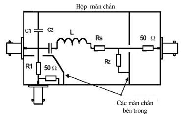
Figure D.2 - Mechanical diagram and equivalent circuit of components
Examples of mechanical diagram and equivalent electrical circuit of the components are given in Figures D.2 and D.1.
If the manufacturer uses antenna inductance, the manufacturer must provide two artificial antennas with maximum and minimum inductance in accordance with the requirements of the laboratory. This must be recorded in the inspection report.
Rz is a pure resistance with low value. The voltage across Rz is proportional to the carrier and spurious emission loop currents. These currents can be measured at terminal C.
Rs combined with Rz ensures that the artificial antenna has the same Q quality factor as the real loop antenna.
Resistor R1 together with load resistor 50 W produce EUT output signal loss at terminal B used for conductive spurious emission measurements between 30 MHz and 1 GHz. R1 > 200 Ω is recommended.
Capacitors C1 and C2 are optional components with inductor L used in accordance with the manufacturer's inductance to simulate a real loop antenna configuration. Other configurations are illustrated in Figure D.3.
![]()
![]()
![]()
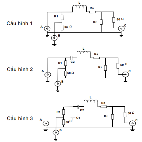
Figure D.3 – Other configurations
The test coupler configuration declared by the manufacturer is stated in the test report and application.
Appendix E
(Informative)
E fields in the near field at low frequencies
E electric field at low frequencies is usually in the near field and H field component can only be easily measured with a screened loop antenna; in this case, there is a relationship between E field and H field through Z-wave impedance. In the near field, the wave impedance is highly dependent on the type of radiated antenna (loop or open-ended terminal wire) and the wavelength. If the power density at some distance is similar for a signal producing an E field and an H field, the following calculation can be made:
In the near-field maximum power direction, power density S is:
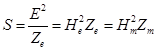 (E.1)
(E.1)
Where:
![]() : power density;
: power density;
![]() : electric field generated by electric field antenna at distance
: electric field generated by electric field antenna at distance ![]() ;
;
![]() : magnetic field generated by E field antenna at distance
: magnetic field generated by E field antenna at distance ![]() ;
;
![]() : magnetic field generated by magnetic field antenna at distance
: magnetic field generated by magnetic field antenna at distance ![]() ;
;
![]() : wave impedance of the field generated by E field antenna at distance d;
: wave impedance of the field generated by E field antenna at distance d;
![]() : wave impedance of the field generated by H field antenna at distance d.
: wave impedance of the field generated by H field antenna at distance d.
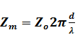 If
If (near field) (E.2)
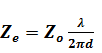 If (near field) (E.3)
from formula (E.1) we have:
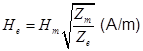 (E.4)
(E.4)
Replace (E.2) and (E.3) into (E.4) we have:
![]() (E.5)
(E.5)
where ![]() is the carrier frequency in MHz.
is the carrier frequency in MHz.
With ![]() ,
, ![]() and
and ![]() MHz, using formula (E.5), we have:
MHz, using formula (E.5), we have:
![]() (
(![]() in MHz) (E.6)
in MHz) (E.6)
For ![]() if
if ![]() MHz, then formula (E.5) is valid, (i.e. near field).
MHz, then formula (E.5) is valid, (i.e. near field).
For ![]() if
if ![]() MHz, then He ≈ Hm .
MHz, then He ≈ Hm .
NOTE: Far-field conditions such as He = Hm and wave impedance of the field Ze = Z m = 377 is valid for d >> 5λ/2π if fc >> 23.86 MHz.
This method allows the generated E field to be measured as H field by adding a correction factor derived from (E.6).
Expressed as a graph of the correction factor given in Appendix B.
Appendix F
(Normative)
Limits and H field measurements at 3 m and 30 m distances
F.0. General
This regulation allows measurements to be made at distances other than 10 m. In this case, corresponding H field limit, Hx, for the measuring distance required by the party whose equipment needs to be tested, dx, must be calculated. Both required measuring distance and the corresponding limit must be stated in the test report.
It is not easy to convert H field limits at a distance of 10 m to a different measuring distance because the near-field to far-field boundaries will vary with both frequency and distance. Different combinations of near/far field and maximum radiated field strength in the coaxial or coplanar direction of the loop antenna, the conversion to the H field limit in this regulation at 3 m or 30 m is a discontinuous curve, see F.1 and F.2.
The conversion methods of P of this Appendix are applicable only if the maximum winding dimension is less than the measuring distance.
F.1. Allowed limits of measurement at a distance of 30 m
H field limit H at 30 m, H 30m, is determined by the following formula:
H30m = H10m + C30 (F.1)
Where:
H10m is H field limit in dBµA/m at a distance of 10 m according to this regulation; and
C30 is the conversion factor in dB determined from Figure F.1.
Conversion factor, C30, for limits at 30 m, dB
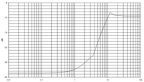
Frequency, MHz
Figure F.1 - Conversion factor C30 compared to frequency
F.2. Limits to measurements at a distance of 3 m
H field limit in dBµA/m at 3 m, H 3m, is determined by the following formula:
H3m = H10m + C3 (F.2)
Where:
H10m is H field limit in dBµA/m at a distance of 10 m according to this regulation; and
C3 is the conversion factor in dB determined from Figure F.2.
Correction factor, C3, for limits at a distance of 3 m, dB
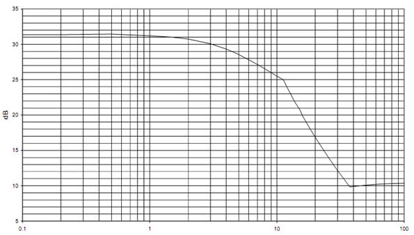
Frequency, MHz
Figure F.2 - Conversion factor C3 compared to frequency
Appendix G
(Normative)
Transmitter’s emission levels and spectral mask measurements
This regulation allows spectral measurements of transmitters to be made. Measurements can be suitable for SRDs operating between 9 kHz and 30 MHz.
The radiated spectral mask must be declared by the manufacturer, subject to the limits in 2.4.7.3 and Figures G.1 and G.2. For more information, see the appropriate Appendix to Recommendation CEPT/ERC 70-03 implemented through the national radio interface (NRI) and the relevant supplementary NRI.
![]()
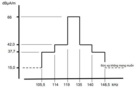
NOTE: The limit at 129.1 kHz ± 500 Hz is maximum 42 dBµA/m at a distance of 10 m.
Figure G.1 - Radiation boundary for LF RFID system
![]()
![]()
![]()
![]()
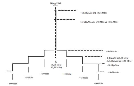
Figure G.2 - Spectral mask limit for RFID, EAS in 6.78 MHz and 13.56 MHz frequency range
![]()
![]()
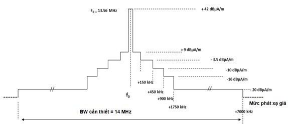
Figure G.3 - Spectral mask limit for RFID broadband (including NFC) in 13.56 MHz frequency range
![]()
![]()
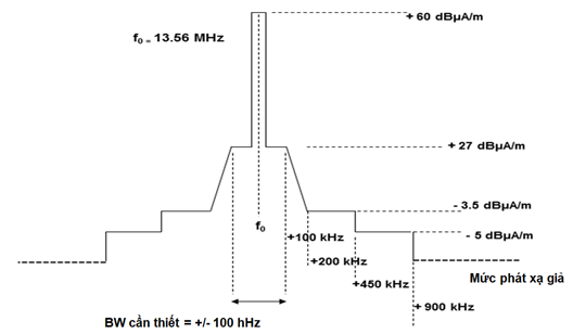
Figure G.4 - Spectral mask limit for RFID narrowband (including NFC) in 13.56 MHz frequency range
Appendix H
(Normative)
General inductive loop limits in 148.5 KHz to 30 MHz frequency range
H.1. Introduction
This Appendix provides additional information about the measurement of induction system at very low magnetic field strength levels.
H.2. Radiated H field strength
H.2.1. Test methods
The test methods must conform to 2.4.3.2 with the following additional provisions, either:
a) For equipment where transmitter modulation can be disabled, the following measurements are applied:
Step 1 Disable transmitter modulation and measure H field strength at a distance of 10 m according to item 2.4.9.2 of this specification using a near-peak detector and a resolution bandwidth of 10 kHz. The result is recorded in the test report in form of total field strength.
Step 2 Enable transmitter modulation and measure transmitter bandwidth according to items 2.4.5 b) and 2.4.6.2, 2.4.7.2. The result is recorded in the test report.
Step 3 Determine the frequency for the maximum value of the spectrum. The frequency is tuned to the center of the spectrum analyzer display.
Step 4 Change Span of spectrum analyzer to 0 Hz and the detector is switched from near peak to positive peak. The measurement result is recorded in the test report as the maximum H field strength density.
Or:
b) For equipment that cannot disable transmitter modulation, the following measurements are applied: Steps 2 to 4 are performed.
Step 1 is irrelevant and cannot proceed.
For carrier’s H field density measurements with ASK modulated transmitter operating in the 400 kHz to 600 kHz frequency range, the modulation cannot be turned off, a value of 3 dB may be subtracted from the measured value.
H.2.2. Radiated H field strength limit
H.2.2.1. Limit of total H field density and radiated H field density according to the measurements in section H.2.1 a)
This limit is applied to equipment that can disable transmitter modulation.
Under normal and extreme test conditions (see 2.2.3 and 2.2.4), the radiated transmitter H field strength for section a) in Article H.2.1 must not exceed the limit for total field intensity and the field density given in Tables H.1 and H.2.
Table H.1 - Limit of radiated H field strength and H field density at a distance of 10 m
Frequency range MHz | Total H field strength at a distance of 10 m (dBµA/m) | H field strength density at a distance of 10 m in 10 kHz resolution bandwidth (dBµA/m) |
0.1485 to 25 | -5 ( see note 1) | -15 ( see note 2) |
NOTE 1: There is no transmitter modulation. Note 2: There is transmitter modulation. | ||
For RFID equipment operating in 400 kHz to 600 kHz frequency range, the following limits are applied:
Table H.2 - Limit of radiated H field strength and H field density at a distance of 10 m for RFID devices
Frequency range MHz | Total H field strength at a distance of 10 m (dBµA/m) | H field strength density at a distance of 10 m in 10 kHz resolution bandwidth (dBµA/m) |
0.400 to 0.600 | -5 ( see note 1) | -8 (see note 2) |
NOTE 1: With transmitter modulation. NOTE 2: The transmission bandwidth must not be less than 30 kHz. | ||
H.2.2.2 Limit of radiated bandwidth and H field density according to the measurements in section H.2.1 b)
This limit is applied to equipment that cannot disable transmitter modulation.o
![]()
![]()
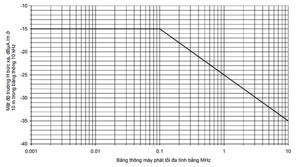
Figure H.1 – Radiated bandwidth and H field density at a distance of 10 m
Appendix I
(Informative)
Way to determine and use measurement bandwidth
CISPR 16-1-4 specifies a reference bandwidth for measuring unwanted emissions with a measuring receiver and spectrum analyzer.
The reference bandwidth (BWREFERENCE) is not always used as the measurement bandwidth (BWMEASUREMENT). This is especially the case if the measurement is made, for example on the slope of the spectrum mask or the receiver’s selectivity curve. In such cases, the measurement must be made with a low enough bandwidth so as not to distort the reading.
The actual measured value, A, must be referred to the reference bandwidth in one of two ways:
a) Correct the measured value, A, for any signal with a flat level spectrum according to the following formula:
![]()
Where:
- B is the measured level converted to the reference bandwidth.
Or:
b) Use measured value A directly if the measured spectrum is a discrete spectral line. A discrete spectral line is defined as a narrow peak with a level at least 6 dB above the mean within the measurement bandwidth.
Appendix J
(Normative)
HS Code of short range device in 9 kHz - 25 MHz frequency range and magnetic loop equipment operating in 9 kHz to 30 MHz frequency range
No. | Name of products and goods according to QCVN | HS code | Description of products and goods |
Short range radio transmitter, receiver- transmitter for general purpose | 8517.62.59 8517.62.69 | Equipment has an external antenna terminal and/or with an integral antenna, intended for the transmission or reception of voice, images or other data; including devices using active NFC (Near Field Communication) technology. | |
2. | Radio alarm and detection equipment | 8526.92.00 | Equipment consists of a sensing element and a control system interconnected via a radio interface for radio alarm and detection purposes |
3. | Radio remote control equipment | 8526.92.00 | Equipment uses radio waves to control models, control in industrial and civil scope. |
4. | Radio Frequency Identification (RFID) equipment | 8517.62.59 | Equipment uses radio waves to automatically identify, track, manage goods, people, animals and other applications. The equipment has two separate units connected via a radio interface: - Radio transceiver, storing information in the form of electronic chip tag (RF tag), mounted on the object to be identified; Only applied to cards with power supply. - Radio transceiver (RF Reader) to activate the radio tag and receive the tag's information, transfer to the data processing system. |
5. | Magnetic loop device | 8504.40.19 8504.40.90 | Short range device operating in the principle of electromagnetic fields, including: - Radio Frequency Identification - Equipment using near-field communication technology - The equipment is used in the security magnetic gate system (EAS) operating in the LF and HF frequency ranges. |
References
[1] ETSI EN 300 330 V2.1.1 (2017-02): Short Range Devices (SRD); Radio equipment in the frequency range 9 kHz to 25 MHz and inductive loop systems in the frequency range 9 kHz to 30 MHz; Harmonised Standard covering the essential requirements of article 3.2 of Directive 2014/53/EU.
You are not logged in.
This feature is available to Advanced account holders. Please log in to access detailed information on Related documents.
If you do not have an account, please register here!
VIETNAMESE DOCUMENTS
This utility is available to subscribers only. Please log in to a subscriber account to download. Don’t have an account? Register here
This utility is available to subscribers only. Please log in to a subscriber account to download. Don’t have an account? Register here
ENGLISH DOCUMENTS
This utility is available to subscribers only. Please log in to a subscriber account to download. Don’t have an account? Register here

