Circular 05/2025/TT-BCT prescribing the electricity transmission, distribution and measuring systems
- Summary
- Content
- Status
- Vietnamese
- Related documents
- Diagram
- Download
Please log in to your Advanced Package to view the full text. Do not have an account yet? Register here.
Please log in to use this function
Please log in to use this function
ATTRIBUTE
| Issuing body: | Ministry of Industry and Trade | Effective date: | Known Please log in to a subscriber account to use this function. Don’t have an account? Register here |
| Official number: | 05/2025/TT-BCT | Signer: | Truong Thanh Hoai |
| Type: | Circular | Expiry date: | Updating |
| Issuing date: | 01/02/2025 | Effect status: | Known Please log in to a subscriber account to use this function. Don’t have an account? Register here |
| Fields: | Electricity, Industry |
The Effect status of this document is known.This feature is available to Advanced account holders. Please log in to a subscriber account to view Effect status. Don’t have an account? Register here
THE MINISTRY OF INDUSTRY AND TRADE | THE SOCIALIST REPUBLIC OF VIETNAM |
CIRCULAR
Prescribing the electricity transmission, distribution and measuring systems
_______________
Pursuant to the Electricity Law dated November 30, 2024;
Pursuant to the Government’s Decree No. 96/2022/ND-CP dated November 29, 2022 defining the functions, tasks, powers and organizational structure of the Ministry of Industry and Trade; the Government’s Decree No. 105/2024/ND-CP dated August 01, 2024 amending and supplementing a number of articles of the Government’s Decree No. 96/2022/ND-CP dated November 29, 2022 defining the functions, tasks, powers and organizational structure of the Ministry of Industry and Trade and Decree No. 26/2018/ND-CP dated February 28, 2018, on the Charter of organization and operation of the Vietnam Electricity;
At the proposal of the Director of Electricity Regulatory Authority of Vietnam;
The Minister of Industry and Trade hereby issues the Circular prescribing the electricity transmission, distribution and measuring systems.
Chapter I
GENERAL PROVISIONS
Article 1. Scope of regulation
This Circular prescribes the technical requirements applicable to the electricity transmission system and the electricity distribution system, including: conditions, technical requirements, and procedures for grid connection; operation of the electricity transmission system and the electricity distribution system; requirements for the measuring system, measurement data acquisition, and measurement data management system; and the responsibilities of relevant entities.
Article 2. Subjects of application
This Circular applies to:
1. Distribution system operators, electricity wholesalers, electricity retailers;
2. Providers of services related to electricity measurement, including: testing and verifying entities; measurement data managing entities;
3. The National Load Dispatch Authority;
4. Electricity producers;
5. Transmission system operators;
6. Electricity customers;
7. Vietnam Electricity;
8. Relevant other organizations and individuals.
Article 3. Interpretation of terms
In this Circular, the terms below are construed as follows:
1. AGC (Automatic Generation Control) means a system of devices that automatically increase or decrease the active power output of generating sets, power stations, power station clusters, or battery energy storage systems to ensure the safe and stable operation of the power system.
2. Security of the electricity supply means the capability of power sources to ensure electricity supply meets the electricity load demand at a specific time or over a defined period, considering the constraints within the power system.
3. AVR (Automatic Voltage Regulator) means an automatic system that regulates the terminal voltage of a generator by acting on the excitation system of the generator to ensure the voltage at the generator terminals remains within permissible limits.
4. Voltage level means one of the values of nominal voltage used in the power system, including:
a) Low voltage means a nominal voltage level of up to 01 kV;
b) Medium voltage means a nominal voltage level from over 01 kV to 35 kV;
c) High voltage means a nominal voltage level of over 35 kV and 220 kV;
d) Ultra-high voltage means a nominal voltage level of over 220 kV.
5. Dispatch Authority in control means a dispatch authority that is authorized to direct and dispatch the power system according to the dispatch hierarchy defined in the Regulations on dispatch, operation, switching, contingency response, black start, and restoration of the national power system promulgated by the Minister of Industry and Trade.
6. Rated power of a power station means the aggregated rated power of all generating sets or wind turbines within such power station. For a solar power station, the rated power of the solar power station means the maximum alternating current power output that such power station can generate, as calculated and published, consistent with the direct current capacity of the solar power station in accordance with the master plan.
7. Rated power of a generating set or wind turbine means the maximum generation output at which it can operate stably and continuously, as published by the manufacturer in accordance with the design, and consistent with the design appraisal document of the competent State authority, as stated in the Power Purchase Agreement of the power station.
8. Available capacity of a generating set means the maximum actual power output that the generating set can stably and continuously generate over a defined period of time.
9. Rated power of a battery energy storage system means the maximum alternating current power that the system can both deliver and absorb, as calculated and published, consistent with the direct current capacity of the battery storage.
10. Voltage fluctuation means the variation in voltage amplitude compared to the nominal voltage for a duration of more than 01 minute.
11. DIM (Dispatch Instruction Management) means an information management system for dispatch instructions between the Dispatch Authority in control and power stations or Control Centers of power stations.
12. Governor deadband means a frequency band within which any change of power system frequency shall not result in reactions or impacts of the governor for regulating primary frequency.
13. Assessment of security of the electricity supply means the evaluation of the stability and safety of electricity supply based on the balance between the available capacity and power of the system and the projected electricity load demand of the system, taking into account the constraints within the power system and the required capacity reserve over a defined period of time.
14. Frequency control in the power system (hereinafter referred to as frequency control) means the control process within the power system to maintain stable operation, including primary frequency control, secondary frequency control, and tertiary frequency control:
a) Primary frequency control means the instantaneous control process of the power system frequency, performed automatically by a large number of generating sets equipped with governors;
b) Secondary frequency control means the subsequent control process following primary frequency control, performed by the action of the AGC system, aiming to restore the frequency to the permissible long-term operating band;
c) Tertiary frequency control means the subsequent control process following secondary frequency control, performed by dispatch instructions to bring the power system frequency to a stable operating point as prescribed by the applicable regulations and to ensure the economic dispatch of generation capacity among the generating sets.
15. Electricity Wholesaler means an electricity entity that is granted the operating license for electricity wholesaling.
16. Electricity Producer means an electricity entity that owns one or more power stations connected to the national power system.
17. Transmission System Operator means an electricity entity that is granted the operating license for electricity transmission.
18. Distribution System Operator means an electricity entity that is granted the operating license for electricity distribution.
19. Electricity Retailer means the electricity entity that is granted the operating license for electricity retailing, or for purchasing wholesale electricity from other electricity sellers to retail electricity to Customers.
20. Reliability of a protection system includes:
a) Actuation reliability of the protection system means an index that determines the probability of the protection system operating properly when a contingency occurs within its calculated and defined protection zone;
b) Non-actuation reliability of the protection system means an index that determines the probability of the protection system avoiding incorrect operation in the normal operating mode or when contingencies occur outside its calculated and defined protection zone.
21. Governor means a device used to regulate rotating speed of the turbine of a generating set in accordance with frequency changes to restore frequency to nominal power system frequency.
22. EMS (Energy Management System) means an energy management software system to optimize operation of the power system.
23. Distributed Control System (DCS) means a control system comprising control devices in a power station or substation that are networked on the principle of distributed control to enhance reliability and limit the impact of control element contingencies within the power station or substation.
24. BESS (Battery Energy Storage System) means a system comprising batteries, a charger, a controller, and other devices connected to the electrical grid to store electrical energy in the batteries during charging and discharge the stored energy when necessary.
25. Measuring System means the system comprising measuring instruments and integrated circuits to measure and determine the amount of electrical energy transmitted through a point of measurement.
26. SCADA (Supervisory Control and Data Acquisition) means a system that acquires data to facilitate the supervision, control, and operation of the power system.
27. Earth fault factor means the ratio between the voltage of the unfaulted phase(s) after an earth fault occurs and the voltage of such phase(s) before the earth fault (applicable to single-phase-to-ground faults or two-phase-to-ground faults).
28. Synchronization means the procedure of connecting a generating set to the power system, or connecting two parts of the power system together, in accordance with the synchronization conditions prescribed in the Regulations on dispatch, operation, switching, contingency response, black start, and restoration of the national power system promulgated by the Minister of Industry and Trade.
29. Black start capability means the capability of a power station to start at least one generating set from a total shutdown without any electrical energy supply from the external area grid to restore part or all of the system.
30. Black start means the process of restoring all (or part) of a power system from a state of total (or partial) blackout by using generating sets with black start capability.
31. Grid User means an organization or individual with electrical equipment and grids connected to the electrical grid to utilize electricity transmission and distribution services, including: generation producer; Transmission System Operator; Distribution System Operator; or Electricity Customer.
32. Significant Distribution Grid User means an organization or individual with electrical equipment and grids connected to the electrical grid to utilize electricity transmission and distribution services, including: generation producer owning power station(s) with a capacity of 03 MW or higher; or Electricity Customer with an average consumption of 1,000,000 kWh per month or higher.
33. Distribution Grid User with their own substation means an Electricity Customer that owns a substation or grid connected to the distribution grid at medium voltage and 110 kV voltage levels.
34. Dispatch instruction means a command or directive controlling the operating mode of the power system in real-time.
35. Distribution grid means the grid comprising lines and substations with the voltage level of up to 110 kV.
36. Transmission grid means the grid comprising lines and substations with the voltage level of more than 110 kV.
37. Short-term flicker perceptibility (Pst) and long-term flicker perceptibility (Plt) means values measured in accordance with the applicable national standards. In cases where Pst and Plt values are not yet available in the national standards, they shall be measured in accordance with the applicable IEC standards published by the International Electrotechnical Commission.
38. Year N means the current Gregorian calendar year of operating the power system.
39. Typical day means a selected day with the characteristic electricity consumption pattern of the electricity load as prescribed in the Regulations on management of electric power demand promulgated by the Minister of Industry and Trade. Typical days include typical working days, weekends (Saturdays and Sundays), holidays (if any) of years, months and weeks.
40. Thermal power station means a power station that operates on the principle of converting thermal energy into electrical energy, including biomass power stations, biogas power stations, and waste-to-energy plants.
41. Contingency-based load shedding means the process of disconnecting electricity load from the power system during a contingency or when there is a threat to the security of the electricity supply, which shall be performed through an automatic contingency-based load shedding scheme or by dispatch instructions.
42. Outage occurrence (contingency) means an event where one or more devices in the power system, due to one or more causes, leads to abnormal operation of the power system, resulting in a power outage or impacting the secure, stable, and continuous electricity supply to the national power system.
43. Single-outage occurrence (single contingency) means a contingency that occurs in one element of the power system while the power system is in normal operating mode.
44. Multiple-outage occurrence (multiple contingency) means a contingency that occurs in two or more elements of the power system at the same time.
45. Severe contingency means a contingency in the power system that causes a widespread power outage on the transmission grid or causes fires or explosions that harm people or property.
46. Remote Terminal Unit/Gateway (RTU/Gateway) means a device located at a substation or power station that acquires and transmits data to the SCADA system of the Dispatch Authority in control or a Control Center.
47. Disconnection means the act of separating the electrical grid or electrical devices of an electrical grid user from the electrical grid at the point of connection.
48. Power System Stabilizer (PSS) means a device that introduces supplementary signals into the Automatic Voltage Regulator (AVR) to dampen power oscillations in the power system.
49. Startup time means the minimum period of time required to start a generating set, calculated from when the Electricity Producer receives a startup instruction from the Dispatch Authority in control until the generating set is synchronized with the national power system.
50. N-1 criterion means a criterion used for power system planning, design, construction investment, and operation to ensure that when a contingency occurs in the power system or when a single element is taken out of service for maintenance or repair, the power system remains stable, meets operational standards and permissible operating limits, and provides a secure and continuous electricity supply.
51. IEC Standards mean the electrical engineering standards issued by the International Electrotechnical Commission (IEC).
52. Automatic contingency-based load shedding means the automatic load shedding of relays triggered by frequency, voltage, or transmission power flow levels of the power system deviating outside permissible thresholds as calculated by the Dispatch Authority in control.
53. Substation means a transformer substation, a switching station, or a compensation station.
54. Control Center means a center equipped with information technology and telecommunications infrastructure system to remotely monitor and control a group of power stations, substations or circuit breakers on the electrical grid.
55. pu means a per-unit system expressing the ratio between actual value and rated value.
56. Automatic Voltage Control (AVC) means an automatic voltage control system designed to maintain the power system voltage within permissible limits and minimize losses on the power system by coordinating the optimal control of devices capable of adjusting voltage and reactive power on the power system.
57. Written record of pre-energization check of the point of connection means a document executed between the Transmission System Operator or the Distribution System Operator and the user requiring grid connection after all parties have checked and agreed that the devices mentioned in the Connection Agreement and installed on-site satisfy the technical requirements prescribed in the Connection Agreement and this Circular.
58. Damping Ratio (ς) means a quantity used to determine the rate at which oscillations decay after a disturbance on the power system. It is determined by the following formula:
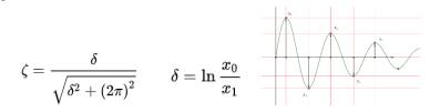
Where x0 and x1 are the amplitudes of any two consecutive oscillation peaks.
59. Current Transformer (CT) means a device that transforms electric current.
60. Voltage Transformer (VT) means a device that transforms electric voltage.
61. Voltage selector switch means a switching device, logic circuit, or auxiliary relay that functions to select voltage.
62. Measurement database means a database that stores measurement data and management and operation information of the Measuring System.
63. Electricity meter means an instrument that measures electrical energy by integrating power over time, storing, and displaying the measured electrical energy values.
64. Measuring System Investor means an organization or individual that invests in and installs the Measuring System and the Measurement Data Acquisition System (if any).
65. Relevant Load Serving Entity means an entity involved in coordinating with other entities in the process of negotiating and reaching agreements on design, investment, installation, operational management of the Measuring System and the Measurement Data Acquisition System, including: Electricity Producer; Transmission System Operator; Electricity Wholesaler; Distribution System Operator; Electricity Retailer; Measurement Data Managing Entity; or Electricity Customer.
66. System Operator means the entity that owns and operates the transmission grid or the distribution grid, including: Transmission System Operator; or Distribution System Operator.
67. Measurement Data Managing Entity means the entity that invests in, installs, manages, and operates the Measurement Data Acquisition System and the Measurement Data Management System within its management scope.
68. Measuring System Operator means the entity that directly manages and operates the Measuring System within its management scope, including: Electricity Producer; Transmission System Operator; Distribution System Operator; Electricity Retailer; or Electricity Customer.
69. Measuring System Owner means the entity that owns the Measuring System and the Measurement Data Acquisition System (if any), including: Electricity Producer; Transmission System Operator; Distribution System Operator; Electricity Retailer; or Electricity Customer.
70. Testing and Verifying Entity means an entity that is granted an operating license for testing, calibration, and verification of measuring instruments in accordance with the law regulations on measurement.
71. Measuring System means a system comprising measuring instruments and measuring circuits integrated to measure and determine the amount of electrical energy transferred through a point of measurement.
72. Measurement Data Acquisition System means a collection of hardware, communication channels, and software that perform the function of acquiring data from electricity meters to the Measuring System Operator or the Measurement Data Managing Entity.
73. Measurement Data Management System means a system comprising hardware, computers, and software that connect to and acquire measurement data from the Measurement Data Acquisition System to perform the functions of processing, calculating, and storing measurement data at the Measurement Data Managing Entity.
74. Junction box means a protective enclosure for the wiring connections of measuring circuit branches and wiring between measuring instruments, equipped with a cover to ensure lead seal integrity.
75. Metering circuit means an electric circuit system linking the measuring instruments for electrical measurement.
76. Measurement data means the electrical energy value measured by electricity meters, calculated electrical energy, or electrical energy estimated based on measurement data, used for energy delivery and billing.
77. Measuring instruments mean instruments including electricity meters, CTs, VTs, and auxiliary equipment used for measuring electrical energy.
78. Measurement information means information about measuring instruments, the Measuring System, and points of measurement, including characteristics, technical parameters, and information related to their management and operation.
79. Point of measurement means a physical location on the primary electrical circuit where the purchased and sold electrical energy is measured and determined.
80. LAN (Local Area Network) means a computer network that interconnects computers within a limited area.
81. WAN (Wide Area Network) means a network that is established to interconnect multiple local area networks extending over a large geographical distance.
82. RS232/RS485 means the standard for serial communication technology between computers and peripheral devices defined by the Electronic Industries Association (EIA).
83. Ethernet means a technology that transmits the data frames and is standardized as IEEE 802.3 used for LAN.
Chapter II
REQUIREMENTS FOR OPERATION OF THE POWER SYSTEM
Article 4. Frequency
1. Nominal frequency of the national power system is 50 Hz. In normal operating mode, power system frequency may fluctuate within ± 0.2 Hz compared with nominal frequency. In other operating modes, permissible frequency band fluctuation and time for restoration of power system to normal operation are prescribed in Table 1 below:
Table 1
Permissible frequency band fluctuations and time for restoration of power system to normal operation at other operating modes of the national power system
Operating mode of the power system | Permissible frequency band fluctuations | Recovery time, from the time of the contingency | |
Unstable state (steady state) | Restoration to normal operating mode | ||
Single contingency | 49 Hz ÷ 51 Hz | 02 minutes to restore the frequency to within the range of 49.5 Hz ÷ 50.5 Hz | 05 minutes to restore the frequency to within the range of 49.8 Hz ÷ 50.2 Hz |
Multiple contingency, severe contingency or extreme emergency mode | 47.5 Hz ÷ 52 Hz | 10 seconds to restore the frequency to within the range of 49 Hz ÷ 51 Hz | 10 minutes to restore the frequency to within the range of 49.8 Hz ÷ 50.2 Hz |
05 minutes to restore the frequency to within the range of 49.5 Hz ÷ 50.5 Hz | |||
2. The permissible frequency band and the permitted number of instances the frequency is outside of the band in cases of multiple contingencies or severe contingencies, or in extreme emergency mode, determined at 01-year or 02-year intervals, are prescribed in Table 2 as follows:
Table 2
Permissible frequency band and acceptable number of beyond-the-limit times in case of multiple contingency, severe contingency or extreme emergency mode
Permissible frequency band (Hz) (“f” is power system frequency) | Permitted number of instances the frequency is outside of the band (from the beginning of the cycle) |
52 ≥ f ≥ 51.25 | 07 instances per year |
51.25 > f > 50.5 | 50 instances per year |
49.5 > f > 48.75 | 60 instances per year |
48.75 > f > 48 | 12 instances per year |
48 ≥ f ≥ 47.5 | Biennial (01 instance in 02 years) |
In which, one instance of the power system frequency exceeding the permissible limit is one instance of the power system frequency exceeding the permissible limit for a period of 05 seconds (s) or more.
3. During the operation of the national power system, the Dispatch Authority in control is responsible for dispatching and operating the national power system and mobilizing ancillary services to ensure the frequency remains within the permissible band.
Article 5. Power system stability
1. Power system stability means the ability of the power system, under specified initial operating conditions, to return to a normal operating mode or a steady-state equilibrium after a disturbance in the power system that alters its operating parameters. Power system stability is classified as follows:
a) Transient Stability means the ability of generating sets in the power system to maintain synchronous operation after a large disturbance in the power system;
b) Small Signal Stability means the ability of generating sets in the power system to maintain synchronous operation after a small disturbance in the power system, with the damping of natural power oscillations within permissible limits;
c) Dynamic Voltage Stability means the ability of the power system to maintain steady-state voltage at nodes after a large disturbance in the power system;
d) Steady State Voltage Stability means the ability of the power system to maintain steady-state voltage at nodes after a small disturbance in the power system;
dd) Frequency Stability means the ability of the power system to maintain steady-state frequency after a disturbance that causes a power imbalance between electricity source and load.
2. Sub-Synchronous Resonance (low-frequency resonance) means the phenomenon where the natural oscillation frequency of the power system resonates with the natural oscillation frequency of the generating set turbine, increasing the torque acting on the turbine shaft and rotor of the generating set.
3. The national power system operating in normal mode or after an N-1 contingency has been cleared must maintain synchronous operation and satisfy the requirements for power system stability prescribed in Table 3 as follows:
Table 3
Power system stability standards
Classification of stability | Stability standards |
Transient Stability | - For oscillations with a frequency less than or equal to 0.05 Hz: the minimum damping ratio is 40%. - For oscillations with a frequency in the range of 0.05 Hz - 0.6 Hz: the half-amplitude damping time is less than 5 seconds. - For oscillations with a frequency greater than 0.6 Hz: the minimum damping ratio required is 5%.
|
Small Signal Stability | The damping ratio shall not be less than 5%. |
Dynamic Voltage Stability | Within 05 seconds after the contingency is cleared, the voltage at the point of failure must recover to at least 75% of the voltage value before the contingency. |
Steady State Voltage Stability | The power system must have a power reserve of at least 5% in accordance with the P-V characteristics in the case of 01 (one) element being taken out of service (N-1). |
Frequency Stability | The power system must ensure compliance with frequency stability standards as prescribed in Clause 1, Article 4 of this Circular. |
Article 6. Voltage
1. Nominal voltage levels:
a) In the transmission grid, the voltage levels include 500 kV and 220 kV.
b) In the distribution system, the voltage levels include 110 kV, 35 kV, 22 kV, 15 kV, 10 kV, 06 kV, and 0.38 kV.
2. Permissible operating voltage deviation in normal operating mode:
a) The permissible operating voltage deviation on the 500kV grid compared to the nominal voltage is ± 05%.
b) The permissible operating voltage deviation on the 220kV grid compared to the nominal voltage is + 10% and - 05%;
c) The permissible operating voltage deviation at the busbars on the distribution grid of the Distribution System Operator compared to the nominal voltage is + 10% and - 05%;
d) The permissible operating voltage deviation at the point of connection to the distribution grid compared to the nominal voltage is as follows:
- At the point of connection with the Electricity Customer, the deviation is ± 05 %;
- At the point of connection with the power station, the deviation is + 10% and - 05 %;
- In cases where the power station and the Electricity Customer are connected to the same busbar or line on the distribution grid, the voltage at the point of connection is decided by the Distribution System Operator managing the regional electrical grid to ensure compliance with the technical requirements for distribution grid operation and to ensure voltage quality for the Electricity Customer as prescribed.
3. In cases where the transmission grid is in single contingency mode, the distribution grid experiences a contingency, or the distribution grid has recovered from a contingency, the permissible voltage fluctuation on the distribution grid is within ± 10% of the nominal voltage.
4. In cases where the transmission system experiences a multiple contingency or a severe contingency, in extreme emergency mode, or in the power system restoration mode, the voltage fluctuation on the transmission grid or the 110kV grid may temporarily exceed ± 10% of the nominal voltage but must not exceed ± 20% of the nominal voltage.
5. For the distribution grid that has not stabilized after a contingency, the permissible voltage deviation at the point of connection with the Electricity Customer directly affected by the contingency is within + 5% and - 10% of the nominal voltage.
6. During a contingency, the voltage at the contingency location and the surrounding region may transiently drop to a value of 0 in the phase with the contingency or rise above 110% of the nominal voltage in the phases without the contingency until the contingency is cleared.
7. In cases where an Electricity Customer has a higher voltage quality requirement than prescribed in Clause 2 of this Article, the Electricity Customer may negotiate with the Distribution System Operator or the Electricity Retailer. The Distribution System Operator or the Electricity Retailer shall be responsible for obtaining the opinion of the Dispatch Authority in control before agreeing with the Customer.
Article 7. Phase balance
1. In normal operating mode, the negative sequence component of the phase voltage must not exceed 03% of the nominal voltage for high voltage and ultra-high voltage levels, or 05% of the nominal voltage for medium voltage and low voltage levels.
2. The negative sequence component of the phase voltage on the power system is permitted to exceed the values prescribed in Clause 1 of this Article at certain times, but 95% of the measured values, with a measurement time of at least 01 week and a sampling frequency of 10 minutes/time, must not exceed the prescribed limit.
Article 8. Harmonics
1. Voltage harmonics
a) Total voltage harmonic distortion means the ratio between the root mean square value of the voltage harmonic and the root mean square value of the fundamental voltage, calculated using the following formula:
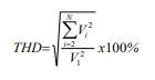
Where:
- THD: Total Voltage Harmonic Distortion;
- Vi: Root mean square value of the ith voltage harmonic, and N is the highest order of the harmonic to be evaluated;
- V1: Root mean square value of the fundamental voltage (with 50 Hz frequency).
b) The maximum permissible voltage harmonic distortion on the power system is prescribed in Table 4a as follows:
Table 4a
Maximum permissible voltage harmonic distortion
Voltage level | Total harmonic distortion (THD) | Individual distortion |
500kV, 220kV | 3.0% | Not available |
110 kV | 3.0% | 1.5% |
Medium voltage | 5.0% | 3.0% |
Low voltage | 8.0% | 5.0% |
2. Current harmonics
a) Total current harmonic distortion is the ratio between the root mean square value of the current harmonic and the root mean square value of the fundamental current at maximum load or generation, calculated on the principle:
![]()
Where:
- TDD: Total Current Harmonic Distortion;
- Ii: Root mean square value of the ith current harmonic, and N is the highest order of the harmonic to be evaluated;
- IL: Root mean square value of the fundamental current (with a frequency of 50 Hz) at maximum load or generation capacity (maximum load or generation capacity means the average value of 12 maximum loads or generation capacities corresponding to the previous 12 months; in case of new connections or where the maximum loads or generation capacities corresponding to the previous 12 months cannot be acquired, the maximum load or generation capacity value during the entire measurement period shall be used).
b) The maximum permissible value of total current harmonic distortion caused by high-order harmonics for voltage levels of 220 kV and 500 kV shall be less than or equal to 3%.
c) Power stations connected to the distribution grid must ensure that current harmonic distortion does not exceed the values prescribed in Table 4b as follows:
Table 4b
Maximum permissible current harmonic distortion for a power station
Voltage level | Total distortion | Individual distortion |
110 kV | 3% | 2% |
Medium voltage and low voltage | 5% | 4% |
d) Electricity loads connected to the distribution grid must ensure that current harmonic distortion does not exceed the values prescribed in Table 4c as follows:
Table 4c
Maximum permissible current harmonic distortion for an electricity load
Voltage level | Total distortion | Individual distortion |
110 kV | 4% | 3.5% |
Medium voltage | 8% | 7% |
Low voltage | 12% if the load ≥50 kW 20% if the load <50 kW | 10% if the load ≥50 kW 15% if the load <50 kW |
3. In normal operating mode, the Transmission System Operator and the Distribution System Operator shall be responsible for ensuring that the total harmonic distortion on the transmission grid and distribution grid does not exceed the values prescribed in Clause 1 of this Article.
4. The Transmission Grid User shall be responsible for ensuring that the devices connected to the transmission grid do not inject harmonics onto the transmission grid exceeding the value prescribed in Clause 2 of this Article.
5. In cases where the total harmonic distortion shows signs of violating the values prescribed in Clause 1 or Clause 2 of this Article, the Transmission Grid User or the Transmission System Operator is entitled to request the other party to check the harmonic values or to engage an independent testing entity to perform the check. In cases where the results of the check indicate that the total harmonic distortion violates the limits prescribed in Clause 1 or Clause 2 of this Article, the party responsible for the cause and violation shall bear all costs of checking, verification, damages, and shall implement remedial measures.
6. Occasional abnormal harmonic peaks on the transmission grid and distribution grid are permitted to exceed the total harmonic distortion limits prescribed in Clause 1 and Clause 2 of this Article, provided that 95% of the measured voltage harmonic and current harmonic values, taken over a measurement period of at least 01 week with a sampling interval of 10 minutes, do not exceed the prescribed limits.
Article 9. Flicker perceptibility
1. Permissible maximum flicker perceptibility in a transmission grid is prescribed in Table 5 below:
Table 5
Flicker perceptibility
Voltage level | Plt95% | Pst95% |
220, 500 kV | 0.6 | 0.8 |
Where: Plt95% is the threshold value of Plt such that for 95% of the measurement time (at least 01 week) and at 95% of the points of measurement, Plt does not exceed this value; Pst95% is the threshold value of Pst such that for 95% of the measurement time (at least 01 week) and at 95% of the points of measurement, Pst does not exceed this value.
2. The Transmission System Operator shall control flicker perceptibility on the transmission grid to ensure that the flicker perceptibility at point of connection must not exceed the value prescribed in Table 5 in normal operating mode. Transmission Grid Users shall ensure flicker perceptibility on the devices connected to the transmission grid must not exceed the value as prescribed in Table 5.
3. In cases where the flicker perceptibility is assumed to show signs of violating the values prescribed in Clause 1 of this Article, the Transmission Grid User or the Transmission System Operator is entitled to request the other party to check the flicker perceptibility or to engage an independent testing entity to perform the check. In cases where the results of the check indicate that the flicker perceptibility violates the limits prescribed in Clause 1 of this Article, the party responsible for the cause and violation shall bear all costs of checking, verification, damages, and shall implement remedial measures.
4. Under normal operating conditions, the flicker perceptibility at all points of connection on the distribution grid shall not exceed the limits prescribed in Table 6 as follows:
Table 6
Flicker perceptibility
Voltage level | Plt95% | Pst95% |
110 kV | 0.60 | 0.80 |
Medium voltage | 0.80 | 1.00 |
Low voltage | 0.80 | 1.00 |
5. Short-term flicker perceptibility (Pst) and long-term flicker perceptibility (Plt) means values measured in accordance with the applicable national standards. In cases where Pst and Plt values are not yet available in the national standards, they shall be measured in accordance with the applicable IEC standards published by the International Electrotechnical Commission.
Article 10. Voltage fluctuation
1. Voltage fluctuation at the point of connection on the transmission grid caused by fluctuating load shall not exceed 2.5% of the nominal voltage and shall remain within the range of permissible operating voltages for each voltage level prescribed in Article 6 of this Circular.
2. Voltage fluctuation at the point of connection on the distribution grid caused by fluctuating load of the Electricity Customer or by the switching of circuit breakers within the power station shall not exceed 2.5% of the nominal voltage and shall remain within the range of permissible operating voltages prescribed in Article 6 of this Circular.
3. In cases where manual on-load tap changing is performed, the voltage fluctuation at the point of connection to the load shall not exceed the voltage adjustment value of the tap step of the on-load tap changer transformer.
4. A maximum voltage adjustment of 5% of the nominal voltage per adjustment is permitted, provided that the voltage adjustment does not damage equipment on the transmission grid and the equipment of the Transmission Grid User.
Article 11. Neutral earthing mode
1. Neutral earthing modes on the electrical grid is prescribed in the Table 7 as follows:
Table 7
Earthing mode
Voltage level | Neutral point |
500kV, 220kV, 110 kV | Direct earthed. |
35 kV | Isolated neutral or impedance earthed. |
15kV, 22kV | Directly earthed (03-phase 03-wire) or with repeated earthing (03-phase 04-wire). |
06kV, 10kV | Isolated neutral. |
Under 1000 V | Direct earthed (neutral earthing, repeated earthing, combined neutral earthing). |
2. In cases where the neutral earthing mode of certain equipment on the electrical grid differs from that prescribed in Clause 1 of this Article, the written consent of the Dispatch Authority in control shall be obtained.
3. The high voltage winding(s) of a three-phase transformer or 03 (three) single-phase transformers connected to the transmission grid shall be star-connected with a neutral point suitable for earthing.
4. The neutral earthing of the transformer shall ensure that the value of the earth fault factor does not exceed the value prescribed in Clause 1, Article 11 of this Circular.
5. Distribution Grid Users shall apply the neutral earthing modes within their own grids as prescribed in Clause 2, Article 11 of this Circular, unless otherwise agreed upon and approved by the Dispatch Authority in control.
6. In cases where an electricity customer is supplied from multiple sources, the customer shall be responsible for installing appropriate protection devices to prevent and limit neutral-to-earth current.
Article 12. Short-circuit current and fault clearing time
1. Permissible maximum short-circuit current
a) The maximum permissible short-circuit current value, the maximum fault clearing time by main protection, and the withstand capability of equipment in the power system are prescribed in Table 8 as follows:
Table 8
Maximum permissible short-circuit current, maximum fault clearing time by main protection, and withstand capability of equipment
Voltage level
| Permissible maximum short-circuit current (kA) | Maximum fault clearing time by main protection (ms) | Minimum withstand time of equipment (s) |
500 kV | 50 | 80 | 01 |
220 kV | 50 | 100 | 01 |
110 kV | 31.5 | 150 | 01 |
Medium voltage | 25 | 500 | 01 |
b) Main protection for electrical equipment means the protection installed and set to protect the entire equipment, ensuring that the criteria for selectivity, actuation reliability, and fault clearing time satisfy the requirements prescribed in Table 8 of this Article when a contingency occurs within the protection zone for the protected equipment;
c) For the 110 kV busbar(s) of 500 kV and 220 kV substations on the transmission grid, the applicable maximum permissible short-circuit current is 40 kA.
2. Circuit breakers on the transmission grid and distribution grid shall have sufficient breaking capacity to interrupt the maximum short-circuit current through the circuit breaker for at least the next 10 years from the scheduled date of commissioning and shall withstand this short-circuit current for a minimum duration of 01 second or more.
3. For hydropower and thermal power generating sets with a capacity greater than 30 MW, the sum of the unsaturated sub-transient reactance of the generator (Xd”-%) and the short-circuit impedance of the step-up transformer (Uk-%), calculated in per-unit values (pu referenced to the rated apparent capacity of the generating set), shall not be less than 40%.
In cases where the above requirement is not met, the project owner shall be responsible for calculating, investing in, and installing additional reactance such that the total value of Xd”, Uk, and the added reactance, calculated in per-unit values (pu referenced to the rated apparent power of the generating set), shall not be less than 40%.
4. For medium voltage lines with multiple sections where protection coordination between circuit breakers on the electrical grid is difficult, the fault clearing time of the main protection at certain circuit breaker locations is permitted to be greater than the value prescribed in Clause 1 of this Article, but must be less than 01 second and must ensure the safety of the equipment and the electrical grid.
5. If the calculated short-circuit current value at the point of connection for an electrical facility connected to the power system is greater than the maximum permissible short-circuit current value prescribed in Table 8, the project owner of such electrical facility shall be responsible for applying measures to reduce the short-circuit current at the point of connection to be less than or equal to the maximum permissible short-circuit current value prescribed in Table 8.
6. The Transmission System Operator and the Distribution System Operator shall be responsible for notifying the maximum short-circuit current value at the point of connection at the present time and as calculated for at least the next 10 years, so that the Grid User can coordinate during the process of investment and installation of equipment, ensuring the circuit breaker has sufficient breaking capacity to interrupt the maximum short-circuit current at the point of connection for at least the next 10 years from the scheduled date of commissioning.
7. The Transmission System Operator and the Distribution System Operator shall be responsible for applying solutions to ensure that the short-circuit current on the electrical grid within their management satisfies the requirements prescribed in Table 8 of this Article. In cases where solutions have been applied but the short-circuit current is still greater than the equipment capability, the Transmission System Operator and the Distribution System Operator shall be responsible for proposing solutions to ensure the safe operation of the equipment.
Article 13. Earth fault factor
1. The earth fault factor of a transmission grid at all voltage levels shall not exceed 1.4.
2. The earth fault factor of a distribution grid shall not exceed 1.4 for directly earthed neutral systems and 1.7 for isolated neutral systems or impedance earthed neutral systems.
Article 14. Reliability of transmission grid
1. The reliability of the transmission grid is determined by the annual ratio of Energy Not Supplied (ENS) due to unplanned supply interruptions or reductions, planned supply interruptions or reductions, and contingencies on the transmission grid causing customer interruptions.
2. Energy Not Supplied (ENS) is calculated as the product of the load interrupted or reduced and the corresponding duration of the interruption or reduction, in cases of power interruption lasting longer than 01 minute, excluding the following cases:
a) Supply interruptions or reductions due to generation shortfall in the national power system;
b) Supply interruptions or reductions due to force majeure events (a force majeure event means any objective, unforeseeable and unavoidable event beyond the reasonable control notwithstanding the adoption of all necessary measures within the available capacity).
3. The ratio of Energy Not Supplied (ENS) for the transmission grid in one year is determined using the following formula:
![]()
Where:
- kkccđ: Ratio of Energy Not Supplied for the transmission grid in 01 year;
- Ti: Duration of the ith supply interruption or reduction lasting longer than 01 minute, determined as the period from the start of the interruption/reduction until supply is restored (hours);
- Pi: Average load interrupted or reduced during the ith instance (kW);
- n: Number of supply interruptions or reductions in the calculation year;
- Att: Total electrical energy transmitted through the transmission grid in the calculation year (kWh).
Article 15. Reliability of distribution grid
1. Service reliability indices of the distribution grid include:
a) System Average Interruption Duration Index - SAIDI;
b) System Average Interruption Frequency Index - SAIFI;
c) Momentary Average Interruption Frequency Index - MAIFI.
2. Reliability indices of the distribution grid shall be calculated as follows:
a) SAIDI is calculated as the sum of power interruption durations lasting longer than 05 minutes experienced by Electricity Customers and Electricity Retailers purchasing electricity from the Electricity Wholesaler, divided by the total number of Electricity Customers and Electricity Retailers purchasing electricity from the Electricity Wholesaler, using the following formula:

Where:
- Ti: Duration of the ith power interruption in month t (considering only interruptions lasting longer than 05 minutes);
- Kᵢ: Total number of Electricity Customers and Electricity Retailers purchasing electricity from the Electricity Wholesaler affected by the ith interruption in month t;
- n: Total number of power interruptions lasting more than 05 minutes in month t within the electricity supply area of the Distribution System Operator;
- Kₜ: Total number of Electricity Customers and Electricity Retailers purchasing electricity from the Electricity Wholesaler in month t;
- SAIDIt (minutes): Index of average interruption duration of the distribution grid in month t;
- SAIDIy (minutes): Index of average interruption duration of the distribution grid in year y.
b) SAIFI is calculated as the total number of customer interruptions lasting longer than 05 minutes experienced by Electricity Customers and Electricity Retailers purchasing electricity from the Electricity Wholesaler, divided by the total number of Electricity Customers and Electricity Retailers purchasing electricity from the Electricity Wholesaler, using the following formula:

Where:
- n: Total number of power interruptions lasting more than 05 minutes in month t within the electricity supply area of the Distribution System Operator;
- Kᵢ: Total number of Electricity Customers and Electricity Retailers purchasing electricity from the Electricity Wholesaler affected by the ith interruption in month t;
- Kₜ: Total number of Electricity Customers and Electricity Retailers purchasing electricity from the Electricity Wholesaler in month t;
- SAIFIt: Index of average interruption frequency of the distribution grid in month t;
- SAIFIy: Index of average interruption frequency of the distribution grid in year y.
c) MAIFI is calculated as the total number of momentary interruptions (lasting 05 minutes or less) experienced by Electricity Customers and Electricity Retailers purchasing electricity from the Electricity Wholesaler, divided by the total number of Electricity Customers and Electricity Retailers purchasing electricity from the Electricity Wholesaler, using the following formula:

Where:
- n: Total number of momentary interruptions in month t within the electricity supply area of the Distribution System Operator;
- Kᵢ: Total number of Electricity Customers and Electricity Retailers purchasing electricity from the Electricity Wholesaler affected by the ith momentary interruption in month t;
- Kₜ: Total number of Electricity Customers and Electricity Retailers purchasing electricity from the Electricity Wholesaler in month t;
- MAIFIt: Index of momentary average interruption frequency of the distribution grid in the month t;
- MAIFIy: Index of momentary average interruption frequency of the distribution grid in the year y.
3. Service reliability shall be monitored and evaluated through two sets of indices, including “Total service reliability” and “Distribution grid service reliability”. Each set of service reliability indices includes 03 indices: SAIDI, SAIFI, and MAIFI, determined as prescribed in this Article.
4. The “Total service reliability” set shall be used to evaluate the quality of electricity supply for customers purchasing electricity from the Distribution System Operator and is calculated as prescribed in this Article, excluding supply interruptions due to the following causes:
a) The Distribution Grid User requests for power cut;
b) Equipment of the Distribution Grid User does not satisfy the technical and electrical safety requirements for supply restoration;
c) The Distribution Grid User’s equipment fails;
d) A force majeure event beyond the control of the Distribution System Operator occurs, or the Distribution Grid User violates law regulations in accordance with the Regulations on the sequence of procedures for interruption and reduction of electricity supply promulgated by the Minister of Industry and Trade.
5. The “Distribution grid service reliability” set is one of the indicators used to evaluate the operational performance of the Distribution System Operator and is calculated as prescribed in this Article, excluding supply interruptions due to the following causes:
a) The cases prescribed in Clause 4 of this Article;
b) A power interruption originates from the transmission grid;
c) Contingency-based load shedding occurs upon dispatch instruction from the Dispatch Authority in control;
d) A power cut is implemented when a serious safety hazard to people and equipment during the operation of the power system is deemed likely.
Article 16. Power loss on transmission grid
Annual power loss on the transmission grid is determined using the following formula:

Where:
- ΔA: Annual power loss on the transmission grid;
- Attnhận: Total annual electrical energy input to the transmission grid, comprising the energy received from all Transmission Grid Users at the points of connection to the transmission grid plus the total imported energy via the transmission grid;
- Attgiao: Total annual electrical energy delivered from the transmission grid, comprising the energy that Distribution System Operators and Electricity Customers directly supplied from the transmission grid receive from the points of connection to the transmission grid plus the total exported energy via the transmission grid.
Article 17. Power loss on distribution grid
Power loss on the distribution grid includes:
1. Technical power loss means power loss caused by the physical nature of power lines and electrical equipment on the distribution grid.
2. Non-technical power loss means power loss influenced by factors in the electricity business management process that are not caused by the physical nature of power lines and electrical equipment on the distribution grid.
3. Before November 15 every year, Vietnam Electricity shall be responsible for developing plans regarding service reliability and power loss for the following year for Distribution System Operators and reporting to the Ministry of Industry and Trade for monitoring purposes.
Article 18. Customer service quality indicators of Distribution System Operators and Electricity Retailers
1. Timeframe for reviewing and executing Connection Agreements and performing new connections or time for modifying connections for customers.
2. Notification time for supply interruptions or reductions.
3. Response quality for customer inquiries and complaints in writing is evaluated based on the following criteria:
a) Clarity level in responding to customer inquiries and complaints in writing, demonstrated through the written response which must include the following details:
- Statement whether the complaint is accepted or not;
- Clear explanation of the proposed solution in cases where the complaint is accepted;
- Express statement of the reasons and guidelines for the customers from the Distribution System Operator or the combined Distribution and Retail Entity on a case-by-case basis in cases where the complaint is not accepted;
- Provision of all other necessary information to help the customer evaluate the proposed solution.
b) The percentage of written responses to customer complaints provided within the time limit prescribed at Point c, Clause 2, Article 19 of this Circular.
c) Quality of receiving customer complaints via telephone shall be evaluated based on the criterion of the percentage of customer calls answered within the time limit prescribed at Point d, Clause 2, Article 19 of this Circular.
Article 19. Customer service quality requirements of Distribution System Operators and Electricity Retailers
1. Distribution System Operators and Electricity Retailers shall organize, maintain, and update an information system to record all inquiries and complaints from customers in writing or via telephone.
2. The customer service quality requirements are prescribed as follows:
a) Timeframe for reviewing and executing the Connection Agreement from the date of receipt of a complete and valid connection request dossier as prescribed in Article 47 of this Circular;
b) Notification time for supply interruptions or reductions as prescribed in the Regulations on the sequence of procedures for interruption and reduction of electricity supply promulgated by the Minister of Industry and Trade;
c) Quality of responding to customer inquiries and complaints in writing: More than 95% of written responses to written complaints shall provide clear responses and comply with the law regulations within a time limit of 05 working days;
d) Quality of receiving customer complaints via telephone: More than 80% of customer telephone calls shall be answered within 30 seconds.
Article 20. Information disclosure on service reliability, power losses, and customer service quality
1. Before the 10th day of each month, the Distribution System Operator shall be responsible for disclosing on its website the information on service reliability, power losses, and customer service quality for the immediately preceding month.
2. Before January 31 every year, the Distribution System Operator shall be responsible for disclosing on its website information on service reliability, power losses, and customer service quality for the immediately preceding year.
Chapter III
CONNECTION TO THE ELECTRICAL GRID
Section 1
GENERAL PRINCIPLES
Article 21. Point of connection
1. Point of connection means the location where a device, grid, or power station of a Grid User connects to the power system, or where the electrical equipment or grids of Transmission System Operators or Distribution System Operators connect to each other.
2. Depending on the structure of the electrical grid and the connection line, the point of connection is determined as follows:
a) For overhead lines, the point of connection is the terminal point of the outgoing line suspension insulator string connected to the disconnector of the substation or the switchyard of the power station;
b) For underground cables, the point of connection is the cable termination on the outgoing side bushing of the disconnector of the substation or the switchyard of the power station.
3. In cases where the point of connection differs from that prescribed in Clause 2 of this Article, the alternative point of connection shall be mutually agreed upon by the two parties.
4. The point of connection shall be described in detail using relevant drawings, diagrams, and descriptions in the Connection Agreement or the Power Purchase Agreement.
Article 22. Asset demarcation boundary and operational management
1. The asset demarcation boundary is marked by the point of connection. The assets of each party at the point of connection shall be listed in detail with relevant drawings and diagrams in the Connection Agreement or the Power Purchase Agreement.
2. Each party shall be responsible for investing, constructing and managing assets of its own in accordance with standards and law regulations, unless otherwise agreed upon.
Article 23. Responsibility for complying with requirements on connection and coordination in connection
1. The Transmission System Operator, the Distribution System Operator, and the Grid User shall be responsible for complying with the connection requirements for electrical devices under their ownership strictly as prescribed in this Circular.
2. The Transmission System Operator and the Distribution System Operator shall be responsible for coordinating the implementation of the connection plan when a customer submits a valid dossier of request for connection. Connection and adjustment of connection shall satisfy the technical requirements for connected devices prescribed in Section 2 of this Chapter.
3. In cases where the equipment at the point of connection of the Grid User does not satisfy the technical requirements and grid operating requirements, the relevant Transmission System Operator or Distribution System Operator shall be responsible for notifying and coordinating with the customer to implement remedial measures. The Grid User shall bear all costs of implementing the remedial measures.
4. The Transmission System Operator and the Distribution System Operator shall be responsible for issuing internal procedures for carrying out their respective tasks, coordinating with customers in order to shorten the time required for executing the Connection Agreement and performing connections for customers.
Article 24. General requirements
1. The Transmission System Operator and the Distribution System Operator shall be responsible for investing in and developing the transmission grid and the distribution grid in accordance with the power development master plan and the approved implementation plan for the master plan, ensuring that grid equipment satisfy the requirements for the operation of the power system as prescribed in Chapter II of this Circular and the technical requirements at the point of connection prescribed in this Chapter.
2. The connection of electrical equipment, grids, and power stations of Transmission Grid Users and Distribution Grid Users to the electrical grid shall be consistent with the power development master plan and the approved implementation plan for the master plan, ensuring that grid equipment satisfies the requirements for the operation of the power system as prescribed in Chapter II of this Circular and the general and specific technical requirements at the point of connection prescribed in this Chapter.
3. In cases where the connection plan proposed by the customer is not consistent with the power development master plan or the approved implementation plan for the master plan, the relevant Transmission System Operator or Distribution System Operator shall be responsible for notifying the customer who wishes to connect, so such adjustments or additions to the plan can be made in accordance with regulations.
4. In cases where the plan for connecting new equipment by the Transmission System Operator or the Distribution System Operator is not consistent with the power development master plan or the approved implementation plan for the master plan, the Transmission System Operator or the Distribution System Operator shall be responsible for reporting to the competent authority to make adjustments or additions to the master plan or implementation plan in accordance with regulations.
5. The Transmission System Operator, the Distribution System Operator, and the customer requesting connection shall have a Connection Agreement using the form prescribed in this Circular, including the following main details:
a) Location of the point of connection;
b) Technical details related to the point of connection;
c) Time schedule for connection completion;
d) Responsibilities for investment and operational management;
dd) Commercial terms of the Connection Agreement.
6. The Transmission System Operator or the Distribution System Operator is entitled to refuse a connection request in the following cases:
a) The device or grid of the customer requesting connection does not satisfy the operational and technical requirements prescribed in this Circular and relevant technical regulations of the industry;
b) The connection request is inconsistent with the power development master plan or the approved implementation plan for the master plan.
7. The Transmission System Operator or the Distribution System Operator is entitled to disconnect the Grid User from the electrical grid in cases where the customer violates the technical and operational requirements prescribed in this Circular or violates regulations on safety and operation related to the assets of the Grid User which may affect the safe operation of the electrical grid.
8. In cases where a Grid User needs to change or upgrade equipment or change the grid connection configuration within their scope of management which may affect the safe operation of the power system or the electrical devices of the Transmission System Operator or the Distribution System Operator at the point of connection, the Grid User shall provide written notice and shall obtain agreement from the Transmission System Operator, the Distribution System Operator, and the Dispatch Authority in control on the plan before implementation.
9. Changes related to the point of connection during investment and operation shall be updated in the records for the point of connection and the executed Connection Agreement.
10. The Grid User shall be responsible for archiving data regarding operating modes, operation, maintenance, and servicing activities, and contingencies on elements within their management scope for a period of 05 years. Upon request from the Transmission System Operator or the Distribution System Operator, the Grid User shall be responsible for fully providing the necessary information related to contingencies occurring on elements within their management scope.
11. For connections for the purpose of purchase/sale or exchange of electricity with foreign countries or connections between power stations located outside the territory of Vietnam and the national power system, the technical requirements and operational requirements for equipment connecting to the electrical grid shall be implemented in the following order of priority:
a) Implementation in accordance with international regulations, treaties, and commitments to which Vietnam is a party;
b) Specific unanimous agreement between the relevant parties to satisfy to the maximum extent possible the technical requirements and regulations regarding the power system of each country and ensure the operation of the interconnected grid and the connecting grid are safe, reliable, and stable.
Section 2
GENERAL TECHNICAL REQUIREMENTS FOR DEVICES CONNECTED TO THE ELECTRICAL GRID
Article 25. Requirements for connected electrical devices
1. The main electrical connection diagram shall fully represent the electrical devices from medium voltage to extra-high voltage levels beyond the point of connection and shall show the interconnection between the grid of the Transmission Grid User and the transmission grid, and between the grid of the Distribution Grid User and the distribution grid. Electrical equipment shall be represented by standard icons and symbols, information on the technical parameters of the equipment, and shall be numbered by the Dispatch Authority in control as prescribed in the Regulations on dispatch, operation, switching, contingency resolution, black start, and restoration of the national power system promulgated by the Minister of Industry and Trade.
2. Circuit breakers directly associated with the point of connection and the accompanying protection, control, and measurement systems shall have sufficient breaking capacity to interrupt the maximum short-circuit current at the point of connection, consistent with the grid and power source development scheme in the power development master plan and the approved implementation plan for the master plan for a period of at least the next 10 years.
3. Devices directly connected to the electrical grid shall have sufficient withstand capability for the maximum possible short-circuit current at the point of connection in accordance with the calculations and notification by the Transmission System Operator or the Distribution System Operator, consistent with the grid and power source development scheme in the power development master plan and the approved implementation plan for the master plan for a period of at least the next 10 years. In cases where the short-circuit current increases beyond the withstand capability of the equipment at a time later than 10 years after the commissioning of the point of connection, the project owner of the connected devices shall be responsible for upgrading or replacing the connected devices or implementing short-circuit current limiting solutions to ensure the withstand capability requirement of the equipment is satisfied.
4. Circuit breakers used for switching operations at the point of connection to the electrical grid shall be equipped with a synchrocheck device if both sides of the circuit breaker have power sources, and shall be equipped with disconnectors integrated with interlocking devices to ensure safety during operation and during equipment maintenance and repair.
Article 26. Requirements for the protective relay system of the transmission system
1. The Transmission System Operator and the Transmission Grid User shall be responsible for designing, installing, setting, and testing the protective relay system within their management scope, ensuring that it satisfies the requirements for fast operation, sensitivity, selectivity, and reliability when clearing contingencies, ensuring safe and reliable operation of the power system. Each power system element (generator, transformer, line, busbar, compensation device, etc.) shall have its own protection system and be independent of the protection systems of other power system elements. The protection system shall be supplied from 02 independent direct current power supplies, ensuring that in cases where one of the two direct current supplies fails, the protective relay system continues to operate normally.
2. The coordination for equipping and installing protective relays at the point of connection shall be agreed upon among the Dispatch Authority in control, the Transmission System Operator, and the Transmission Grid User. The Transmission System Operator or the Transmission Grid User shall not arbitrarily change protective devices and the settings of protective relays without the consent of the Dispatch Authority in control.
3. The Dispatch Authority in control shall be responsible for issuing relay setting sheets within the transmission grid of the Transmission System Operator and approving the relay settings of the protective relays of the Transmission Grid User.
4. The maximum fault clearing time on elements within the power system of the Transmission Grid User by main protection shall not exceed the values prescribed in Article 12 of this Circular.
5. In cases where the protective devices of the Transmission Grid User are required to be connected to the protective devices of the Transmission System Operator, such equipment shall satisfy the connection requirements of the Transmission System Operator and be approved by the Dispatch Authority in control.
6. In cases where a contingency occurs on the grid of the Transmission Grid User, the protective relay devices on the Transmission Grid User’s grid may be permitted to send tripping commands to circuit breakers on the transmission grid, but this requires the approval of the Transmission System Operator and the Dispatch Authority in control regarding these circuit breakers and shall be prescribed in the Connection Agreement.
7. The actuation reliability of the protective relay system shall not be less than 99%.
8. In addition to the requirements prescribed from Clause 1 to Clause 7 of this Article, the protective relay systems of the Transmission Grid User and the Transmission System Operator shall also satisfy the following additional requirements:
a) Power stations shall be equipped with an accurate synchronization system;
b) Power stations shall be equipped with a fault recording monitoring system having GPS (Global Positioning System) time synchronization functionality;
c) Power stations with a total installed capacity of 300 MW or higher shall be equipped with devices having phasor measurement functionality (PMU - Phasor Measurement Unit) and GPS (Global Positioning System) time synchronization. For power stations with a total installed capacity below 300 MW, the equipping of PMUs shall depend on the calculations and requirements of the Dispatch Authority in control;
d) The Transmission System Operator and Transmission Grid Users that are not Electricity Producers shall be responsible for equipping and installing fault recorders and phasor measurement devices (PMUs) in accordance with the calculations and requirements of the Dispatch Authority in control, ensuring compatible, reliable, and stable connection with the fault recording and phasor measurement system located at the National Load Dispatch Authority. The Dispatch Authority in control shall be responsible for providing technical specifications for fault recorders and phasor measurement devices ensuring compatible connection and reliable, stable operation with the system at the Dispatch Authority in control and integrating the fault recorders and phasor measurement devices of the Transmission System Operator and Transmission Grid Users with the system located at the Dispatch Authority in control;
dd) During operation, should the need arise to upgrade or replace fault recorders or phasor measurement devices, the Transmission System Operator and Transmission Grid Users shall be responsible for notifying and agreeing with the Dispatch Authority in control before implementation;
e) Transmission lines with a voltage level of 220 kV or higher connecting a generating set or a power station switchyard shall have 02 independent telecommunication channels for the purpose of transmission of protective relay signals between the two ends of the line with a transmission time not exceeding 20 ms;
g) The Transmission System Operator and Transmission Grid Users shall be responsible for investing in and installing under-frequency relays and under-voltage relays within their management scope for the purpose of automatic contingency-based load shedding in accordance with the calculations and requirements of the Dispatch Authority in control.
9. The Dispatch Authority in control of the national power system and the Dispatch Authority in control of the distribution system shall be responsible for organizing the development and issuance of the scope, arrangement, and technical requirements for protective relay devices for generating sets, transformers, busbars, and lines connecting to the transmission grid, reporting to the Ministry of Industry and Trade before application.
Article 27. Requirements for the protective relay system of the distribution system
1. The Distribution System Operator and Distribution Grid Users with their own substations shall be responsible for designing, installing, setting, testing, and operating the protection system on the grid within their management scope to satisfy the standards and requirements for operating time, sensitivity, and selectivity when clearing contingencies, ensuring safe and reliable operation of the distribution system.
2. The Distribution System Operator and Distribution Grid Users with their own substations shall agree upon the requirements for the protection system in the Connection Agreement. The coordination for equipping and installing protective relays at the point of connection shall be agreed upon among the Distribution System Operator, the Distribution Grid User, and the Dispatch Authority in control during the Connection Agreement negotiation process. The Distribution System Operator or the Distribution Grid User shall not arbitrarily change protective devices and the settings of protective relays without the consent of the Dispatch Authority in control.
3. The Distribution System Operator shall provide to Distribution Grid Users with their own substations the parameters of the protective relay system on the distribution grid directly related to the customer’s protection system at the point of connection during the Connection Agreement negotiation process. The Dispatch Authority in control shall be responsible for calculating, checking, and issuing protective relay setting sheets or approving the settings on the distribution grid under its control in accordance with the Regulations on dispatch, operation, switching, contingency resolution, black start, and restoration of the national power system promulgated by the Minister of Industry and Trade.
4. Distribution Grid Users with their own substations shall not arbitrarily install devices to limit short-circuit current at the busbar connecting to the distribution grid, unless otherwise agreed upon with the Distribution System Operator and the Dispatch Authority in control.
5. The maximum fault clearing time on elements within the power system of the Distribution Grid User by main protection shall not exceed the values prescribed in Article 12 of this Circular.
6. In cases where the protective devices of the Distribution Grid User are required to be connected to the protective devices of the Distribution System Operator, such devices shall satisfy the connection requirements of the Distribution System Operator and be approved by the Dispatch Authority in control.
7. In addition to the requirements prescribed in Clauses 1, 2, 3, 4, 5, and 6 of this Article, the protection systems of power stations and Distribution Grid Users with their own substations connected at the voltage level of 110 kV shall satisfy the following requirements:
a) 110 kV voltage level power lines connecting the power station to the national power system shall have 02 (two) independent telecommunication channels for the purpose of transmission of protective relay signals between the two ends of the line with a transmission time not exceeding 20 ms;
b) Distribution Grid Users with their own substations connected at the voltage level of 110 kV shall be responsible for investing in and installing under-frequency relays for the purpose of automatic contingency-based load shedding in accordance with the calculations of the Dispatch Authority in control.
Article 28. Requirements for the information system of the transmission system
1. The Transmission Grid User shall be responsible for investing in, installing, managing, and operating the information system within their management scope and ensure the connection of this system with the information system of the Transmission System Operator and the Dispatch Authority in control; ensuring communication and data transmission (including data from SCADA systems, PMUs, and fault recording monitoring) are complete, reliable, and continuous for the purpose of operation of the power system and the electricity market. The minimum means of communication for the purpose of dispatch and operation of the transmission system include direct channels, telephone, DIM, and computer networks.
2. The information system of the Transmission Grid User shall be compatible with the information systems of the Transmission System Operator and the Dispatch Authority in control.
The Customer may agree to use the information system of the Transmission System Operator or that of other providers to connect to the information system of the Dispatch Authority in control to ensure continuous and reliable information for the purpose of operation of the power system and the electricity market.
3. The Transmission System Operator shall be responsible for investing in and managing the information system within the scope of transmission grid management to serve the management and operation of the power system and the electricity market; coordinate with the Dispatch Authority in control to establish communication links to the Dispatch Authority in control.
4. The Dispatch Authority in control shall be responsible for providing to the Transmission System Operator and the Transmission Grid User the requirements for information data, data transmission, and necessary information interfaces for the purpose of operation of the power system and the electricity market.
5. The Dispatch Authority in control and the Transmission System Operator shall be responsible for coordinating with the Transmission Grid User in testing, checking, and connecting the customer’s information and data systems to the existing information and data systems within their management.
6. Requirements for the information system that do not fall under the cases prescribed in Clause 1 of this Article shall be mutually agreed upon by the entities and must be clearly stated in the Connection Agreement.
7. The Transmission System Operator and the Grid User shall be responsible for investing in, managing, and operating the information system within their management scope to ensure continuous and reliable information to the Dispatch Authority in control for the purpose of operation of the transmission system.
8. The Dispatch Authority in control and the Transmission System Operator shall be responsible for coordinating with each other in providing to Grid Users the necessary requirements for information data and information interfaces and coordinating with customers in testing, checking, and connecting the customers’ information and data systems with the existing information and data systems within their management scope for the purpose of operation of the transmission system.
Article 29. Requirements for the information system of the distribution system
1. Power stations connected to the distribution grid with a capacity of 10 MW or higher or 110 kV substations shall be equipped with an information system and ensure this system is compatibly connected with the information system of the Dispatch Authority in control, for the purpose of communication and data transmission for operation of the power system. The minimum means of communication for the purpose of dispatch include direct channels, telephone, DIM, and computer networks.
2. Requirements for the information system that do not fall under the cases prescribed in Clause 1 of this Article shall be mutually agreed upon by the entities and must be clearly stated in the Connection Agreement.
3. The Distribution System Operator and the Distribution Grid User shall be responsible for investing in, managing, and operating the information system within their management scope to ensure continuous and reliable information to the Dispatch Authority in control for the purpose of operation of the distribution system.
4. The Dispatch Authority in control and the Distribution System Operator shall be responsible for coordinating with each other in providing to Distribution Grid Users the necessary requirements for information data, data transmission, and information interfaces and coordinating with customers in testing, checking, and connecting the customers’ information and data systems with the existing information and data systems within their management scope for the purpose of operation of the distribution system.
Article 30. Requirements for connection to the SCADA system
1. Substations with a voltage level of 110 kV or higher, power stations with an installed capacity of 10 MW or higher (regardless of connection voltage level), and power stations connected to the electrical grid not yet connected to a Control Center shall be equipped with a Gateway or RTU and establish two physically independent connections with the SCADA system of the Dispatch Authority in control.
2. Substations with a voltage level of 110 kV or higher, power stations with an installed capacity of 10 MW or higher (regardless of connection voltage level), and power stations connected to the electrical grid already connected to a Control Center shall be equipped with a Gateway or RTU and shall establish one connection with the SCADA system of the Dispatch Authority in control and two connections with the control system at the Control Center. 110 kV substations that are remotely controlled and operated from a Control Center shall be equipped with a Gateway or RTU establishing two connections with the control system at the Control Center, and the Control Center shall share information from this system with the Dispatch Authority in control.
3. For power stations with an installed capacity below 10 MW connected to the distribution grid, the Distribution System Operator shall be responsible for coordinating with the Dispatch Authority in control and the power station project owner to agree upon the requirements for connection to the SCADA system. In cases where the parties agree to connect SCADA signals from the power station to the Dispatch Authority in control, full compliance with the detailed technical requirements regarding the operational management of the SCADA system prescribed by the Dispatch Authority in control is required.
4. Requirements for connection to the SCADA system of the Dispatch Authority in control not falling under the cases prescribed in Clause 1, Clause 2, and Clause 3 of this Article shall be mutually agreed upon by the relevant entities and clearly specified in the Connection Agreement. In this case, the Transmission System Operator or the Distribution System Operator shall be responsible for coordinating with the Dispatch Authority in control to agree upon the requirements for connection to the SCADA system within the Connection Agreement.
5. In cases where a power station or substation has multiple dispatch authorities in control, the dispatch authorities shall be responsible for agreeing upon and sharing information for the purpose of coordinated operation of the power system.
6. Owners of power stations and substations shall be responsible for investing in, installing, managing, and operating the RTU/Gateway within their management scope and the data transmission lines, or leasing data transmission lines from service providers, to ensure that the connection and data transmission to the SCADA system of the Dispatch Authority in control and the control system of the Control Center (if any) are continuous, complete, and reliable.
7. The RTU/Gateway of the Transmission System Operator, the Distribution System Operator, and the Grid User shall have compatible technical characteristics and ensure connectability with the SCADA system of the Dispatch Authority in control and the control system of the Control Center (if any).
8. The Dispatch Authority in control shall be responsible for integrating data in accordance with the list of data agreed with the Transmission System Operator, the Distribution System Operator and the Grid User to its SCADA system. The Transmission System Operator, the Distribution System Operator, and the Grid User shall be responsible for coordinating with the Dispatch Authority in control in configuring and establishing the database on their systems ensuring compatibility with the SCADA system of the Dispatch Authority in control and the control system of the Control Center (if any).
9. The Dispatch Authority in control, the Transmission System Operator, the Distribution System Operator, and the Grid User shall be responsible for coordinating the implementation of necessary adjustments so that equipment on the electrical grid is compatible with changes to the SCADA system, in cases where the SCADA system of the Dispatch Authority in control undergoes technological changes and such changes are approved by the competent authority after the signing date of the Connection Agreement, leading to the need for changes or upgrades to the control systems and the RTU/Gateway of the Transmission System Operator, the Distribution System Operator, and the Grid User. The Transmission System Operator, the Distribution System Operator, and the Grid User shall be responsible for investing in and upgrading the control systems and the RTU/Gateway to ensure compatible connection with the SCADA system of the Dispatch Authority in control.
10. During operation, should the need arise to upgrade, expand, or replace the control systems and the RTU/Gateway, the Transmission System Operator, the Distribution System Operator, and the Grid User shall be responsible for agreeing with the Dispatch Authority in control before implementing the upgrade, expansion, or replacement.
11. The National Load Dispatch Authority shall be responsible for organizing the development of and agreeing with other dispatch authorities to issue the sequence of procedures for agreement implementation and detailed technical requirements regarding the operational management of the SCADA system, and reporting it to the Ministry of Industry and Trade before application.
Article 31. Requirements for power factor
1. In normal operating mode, the Distribution System Operator and electricity customers directly supplied from the transmission grid shall maintain the power factor (cosj) at the primary point of measurement at not less than 0.9 in cases of receiving reactive power and not less than 0.98 in cases of reactive power injection.
2. The Transmission Grid User shall provide to the Transmission System Operator and the Dispatch Authority in control the parameters regarding reactive power compensation devices within their grid (if any), including:
a) Rated reactive power and adjustment band;
b) Principle of reactive power adjustment.
3. Electricity customers using electricity for production, business, or service purposes who have their own substations, or who do not have their own substations but have a maximum demand of 40 kW or higher, shall be responsible for maintaining the power factor (cosj) at the installation point of the electricity measuring instruments in accordance with the Power Purchase Agreement at not less than 0.9.
Article 32. Load fluctuation
The rate of change of power consumption over 01 minute for electricity customers directly supplied from the transmission grid or for Distribution Grid Users with their own substations shall not exceed 10% of the power consumption during operation in normal mode unless the electricity customer can adjust electricity usage demand as required or has another agreement with the National Load Dispatch Authority.
Article 33. Automatic contingency-based load shedding system
1. The Transmission System Operator, the Distribution System Operator, and the Grid User shall be responsible for coordinating with relevant entities to agree upon the installation of equipment and ensure the operation of the automatic contingency-based load shedding system within their respective power systems in accordance with the calculations and requirements of the Dispatch Authority in control.
2. The automatic contingency-based load shedding system shall be designed and set to satisfy the following requirements:
a) Reliability not less than 99%;
b) The unsuccessful shedding of any load shall not affect the operation of the entire power system;
c) The sequence of procedures for shedding and the amount of shed capacity shall comply with the allocation from the Dispatch Authority in control, and not be changed under any circumstances without the permission of the Dispatch Authority in control.
3. The sequence of procedures for restoring electrical load shall comply with the dispatch instruction(s) from the Dispatch Authority in control.
Article 34. Requirements for Control Centers
1. General technical requirements
a) The monitoring, control, and information systems installed at the Control Center shall be equipped with devices to ensure the safe and reliable operation of the power stations and substations operated by the Control Center;
b) The monitoring and control system of the Control Center shall have compatible technical characteristics and ensure that the connection and data transmission from power stations, substations, and circuit breakers on the electrical grid to the SCADA system of the Dispatch Authority in control are stable, reliable, and continuous;
c) The Control Center shall have backup power supplies to ensure normal operation in cases where power supply from the national power system is lost.
d) The total rated power of renewable energy (wind or solar) power stations under the Control Center shall not exceed the rated power of the largest generating set currently connected within the national power system, as determined by the National Load Dispatch Authority.
dd) The Control Center shall issue contingency resolution procedures for loss of connection of the information system, control signals, the SCADA system and send them for comments from the relevant Dispatch Authority in control before approval.
2. Connection requirements of the Control Center
a) Requirement for connection to the information system
- One data transmission line shall be connected to the information system of the Dispatch Authority in control. In cases where multiple dispatch authorities in control exist, an information sharing method must be agreed by all the dispatch authorities in control;
- Two data transmission lines (one operational line, one hot stand-by line) shall be connected to the control and information systems of the power station or substation that are remotely controlled by the Control Center;
- The minimum means of communication for the purpose of dispatch between the Dispatch Authorities in control and the Control Center include direct channels, telephone, DIM, and computer networks. The minimum means of communication between the Control Center and the power stations and substations include direct channels, telephone, and computer networks.
b) Requirements for connection to the SCADA system
- One connection shall be established with the SCADA system of the Dispatch Authority in control. In cases where multiple dispatch authorities in control exist, the Control Center shall connect directly to the most superior Dispatch Authority in control, and the dispatch authorities shall be responsible for sharing information;
- Two connections shall be established with the RTU or Gateway, the control system of the power station, substation, and circuit breakers on the electrical grid that are remotely controlled by the Control Center.
c) The Control Center shall be equipped with monitoring screens and be connected to the security camera surveillance system at the power stations and substations.
3. Power stations and substations remotely controlled by the Control Center shall be equipped with monitoring and control systems, cameras, and telecommunication information systems to transmit and connect data stably, reliably, and continuously with the Control Center, satisfying the requirements in Clause 1 and Clause 2 of this Article.
Section 3
TECHNICAL REQUIREMENTS FOR CONNECTION TO HYDROPOWER STATIONS AND THERMAL POWER STATIONS
Article 35. Requirements for mobilization and power control capability of generating sets connected to the transmission grid or generating sets of power stations with an installed capacity above 30 MW connected to the distribution grid
1. Power stations with an installed capacity above 30 MW shall invest in equipment, control systems, and the AGC system ensuring stable, reliable, and secure connection with the generating set power control system of the National Load Dispatch Authority for the purpose of remote control of generating sets’ power output in accordance with dispatch instructions from the National Load Dispatch Authority. For power stations located in industrial parks that only sell a portion of their electricity output to the national power system, and for combined heat and power stations where the change in generating sets’ power output depends on other industrial production lines within the plant, the necessity of equipping an AGC system shall be agreed upon by the parties and clearly specified in the specialized technical agreements with the Dispatch Authority in control.
2. Generating sets of power stations shall be capable of injecting rated active power within a power factor range from 0.85 (corresponding to reactive power injection mode) to 0.9 (corresponding to reactive power absorption mode) at the generator terminals.
3. Generating sets of power stations (excluding steam tail sets of combined cycle power stations) shall be capable of engaging in primary frequency control when the frequency deviates outside the deadband of the governor system and delivering at least 50% of the generating set’s primary frequency control power within the first 15 seconds, 100% of the generating set’s primary frequency control power within 30 seconds, and maintaining this power for at least the next 15 seconds. The primary frequency control power of the generating set is calculated based on the actual frequency deviation, the remaining available capacity of the generating set, the primary response capability limit in accordance with the generating set’s technology, and the setting parameters required by the National Load Dispatch Authority. The primary response capability limit in accordance with the generating set’s technology, provided by the Electricity Producer, based on documents and confirmation from the manufacturer, shall not be lower than 3% of the rated power of the generating set.
4. In normal operating mode, voltage changes at the point of connection to the transmission grid within the permissible range as prescribed in Article 6 of this Circular shall not affect the amount of active power being delivered nor the capability to deliver the full reactive power of the generating set.
5. Generating sets of power stations shall be capable of continuously injecting rated active power within the frequency band from 49 Hz to 51 Hz. Within the frequency band from 46 Hz to below 49 Hz and above 51 Hz, the power reduction level shall not exceed the value calculated in accordance with the proportional requirement of the power system frequency reduction, consistent with the active power-frequency characteristic curve of the generating set. The minimum durations for which power stations with an installed capacity above 30 MW or power stations connected to the transmission grid shall maintain generation of electricity corresponding to the frequency bands of the power system are prescribed in Table 9 as follows:
Table 9
Minimum durations for which the generation of electricity is maintained corresponding to the frequency bands of the power system
Frequency band of the power system | Minimum duration of maintenance | |
Hydropower stations | Thermal power stations | |
From 46 Hz to 47.5 Hz | 20 seconds | Not required |
From 47.5 Hz to 48.0 Hz | 10 minutes | 10 minutes |
From over 48 Hz to under 49 Hz | 30 minutes | 30 minutes |
From 49 Hz to 51 Hz | Continuous generation | Continuous generation |
From over 51 Hz to 51.5 Hz | 30 minutes | 30 minutes |
From over 51.5 Hz to 52 Hz | 03 minutes | 01 minutes |
6. Generating sets of power stations shall be capable of withstanding the level of voltage asymmetry in the power system as prescribed in Article 7 of this Circular and withstanding the negative sequence and zero sequence current components appearing during the time for clearing phase-to-phase and phase-to-earth short circuits near the generator by backup protection associated with the point of connection without being permitted to disconnect from operation.
7. Generating sets of power stations shall be capable of continuous operation in the following modes:
a) Unbalanced load between the three phases: 10% or less;
b) Excitation system response ratio for synchronous generating sets: more than 0.5%;
c) Negative sequence current: less than 5% of the rated current.
8. The generating sets of a power station must maintain connection to the grid when the rate of change of frequency of the power system is within the band from 0 Hz/second to 01 Hz/second, as measured over a 500-millisecond time window.
Article 36. Requirements for generating sets of hydropower stations and thermal power stations with a capacity up to 30 MW connected to the distribution grid
Requirements for generating sets of hydropower stations and thermal power stations (including biomass power stations, biogas power stations, and waste-to-energy plants):
1. It must be capable of generating rated active power continuously within the frequency band from 49 Hz to 51 Hz. Within the frequency band from 47.5 Hz to 49 Hz, the power reduction level shall not exceed the value calculated in accordance with the proportional requirement of the power system frequency reduction, consistent with the active power-frequency characteristic curve of the generating set. Minimum durations for which the generation of electricity is maintained corresponding to the frequency bands of the power system are prescribed in Table 10 as follows:
Table 10
Minimum durations for which the generation of electricity is maintained corresponding to the frequency bands of the power system
Frequency band of the power system | Minimum duration of maintenance |
From 47.5 Hz to 48.0 Hz | 10 minutes |
From 48 Hz to 49 Hz | 30 minutes |
From 49 Hz to 51 Hz | Continuous generation |
From 51 Hz to 51.5 Hz | 30 minutes |
From 51.5 Hz to 52 Hz | 01 minutes |
2. Generating sets connected to the distribution grid shall be capable of continuously injecting and absorbing reactive power with a power factor range from 0.9 (corresponding to reactive power injection mode) to 0.95 (corresponding to reactive power absorption mode) at rated power and maintaining the voltage deviation within the band prescribed in Article 6 of this Circular;
3. Generating sets connected to the distribution grid shall be capable of withstanding the level of voltage asymmetry in the power system as prescribed in Article 7 of this Circular and withstanding the zero sequence and negative sequence current components for no less than the time for clearing phase-to-phase and phase-to-earth short circuits near the generator by backup protection associated with the point of connection;
4. In cases where the point of connection is equipped with an auto-reclosing device, the protective relay system of the power station shall ensure coordination with the auto-reclosing device of the Distribution System Operator and shall be designed to ensure the generating set is disconnected from the distribution grid immediately after the circuit breaker, auto-reclosing device, or sectionalizer of the distribution grid opens for the first time, and maintain isolation of the generating set from the distribution grid until the distribution grid is fully restored;
5. Power stations with a total installed capacity of 30 MW or less connected to the 110 kV voltage level grid shall be equipped with a governor capable of operating with static regulation characteristic values (droop) within a range from 03% to 05% and a governor deadband within ± 0.05 Hz.
6. The generating sets of a power station must maintain connection to the grid when the rate of change of frequency of the power system is within the band from 0 Hz/second to 01 Hz/second, as measured over a 500-millisecond time window.
Article 37. Excitation system of a generating set
1. The excitation system of the generating set shall ensure that the generating set can operate within the power factor ranges prescribed in Clause 2, Article 36 and Clause 2, Article 35 of this Circular. The excitation system shall ensure that the generating set operates at rated apparent power (MVA) within the range of ± 5% of the rated voltage at the generator terminals.
2. Generating sets of power stations shall be equipped with a continuously operating AVR capable of maintaining the terminal voltage with a deviation not exceeding ± 0.5% of the rated voltage throughout the entire permissible operating band of the generator.
3. The AVR shall be capable of compensating for the voltage drop across the generator step-up transformer (GSU) and ensuring stable reactive power sharing among generators connected to a common busbar.
4. The response time of the AVR shall be no less than 2.5s for a 5% step change in rated voltage when disconnected from the grid and less than 5s for a 5% step change in rated voltage when connected to the grid, measured from the time the AVR system receives the control signal.
5. The AVR shall allow setting limits for:
a) Minimum excitation current;
b) Maximum excitation current.
6. When the generator terminal voltage is within the range from 80% to 120% of the rated voltage and the system frequency is within the band from 47.5 Hz to 52 Hz, for a maximum duration of 0.1 seconds the excitation system of the generating set shall be capable of increasing the excitation voltage to the following values:
a) For generating sets of hydropower stations: 1.8 times the rated value;
b) For generating sets of thermal power stations: 2.0 times the rated value.
7. The rate of change of excitation voltage shall not be less than 2.0 times the rated excitation voltage per second when the generating set is operating on rated load.
8. Generating sets of power stations with a capacity above 30 MW shall be equipped with a Power System Stabiliser (PSS) capable of damping oscillations with frequencies within the band from 0.1 Hz to 5 Hz, contributing to enhancing power system stability. The Electricity Producer shall set and adjust the parameters of the PSS device to ensure the PSS device has a damping ratio of no less than 5%. For generating sets equipped with a PSS device, the Electricity Producer shall be responsible for putting the PSS device into operation as required by the Dispatch Authority in control.
Article 38. Governor of a generating set
1. Generating sets of power stations, when operating, shall engage in primary frequency regulation within the national power system.
2. Generating sets of power stations shall be equipped with a fast-acting governor system capable of responding to system frequency changes under normal operating conditions. The governor system shall be capable of receiving and executing commands to increase, decrease, or change the power setpoint from the SCADA/EMS of the National Load Dispatch Authority, unless otherwise required by the National Load Dispatch Authority.
3. The governor system of the generating set shall be capable of having the static regulation characteristic value (droop) set to less than or equal to 5%. The setting value of the static regulation characteristic (droop) shall be calculated and determined by the National Load Dispatch Authority.
4. Excluding steam tail generating sets of combined cycle power stations, the minimum settable value of the governor system deadband for generating sets shall be within the range of ± 0.05 Hz. The governor system deadband value for each generating set shall be calculated and determined by the National Load Dispatch Authority during the connection and operation process.
5. The governor control system shall allow setting limits and overspeed protections as follows:
a) For steam turbines: From 104% to 112% of the rated speed;
b) For gas turbines and hydro turbines: From 104% to 130% of the rated speed;
c) In cases where a generating set operates in a grid area temporarily disconnected from the national transmission system but continues to supply electricity to customers, the generating set governor system shall be capable of maintaining frequency stability for the disconnected grid area.
Article 39. Black start
1. At important locations in the transmission system, certain power stations shall have black start capability. Requirements for black start capability shall be clearly stated in the Connection Agreement.
2. The Dispatch Authority in control shall be responsible for identifying important locations within the national power system where power stations with black start capability need to be constructed and providing comments to the Transmission System Operator during the connection review process. The Transmission System Operator shall agree with the Electricity Producer on the black start requirements for the power station during the Connection Agreement negotiation process and specify them in the Connection Agreement.
Section 4
TECHNICAL REQUIREMENTS FOR WIND POWER STATIONS AND SOLAR POWER STATIONS
Article 40. Technical requirements for wind power stations and solar power stations connected to the transmission grid and for generating sets of wind power stations and solar power stations with an installed capacity of above 30 MW connected to the distribution grid
1. Wind and solar power stations must be capable of maintaining generation of active power in the following modes:
a) Unrestricted generation mode: Generate the maximum possible power output based on the variability of the primary energy source (wind or solar);
b) Power output control mode:
A wind power station or solar power station must be capable of limiting their power output in accordance with dispatch instructions in the following cases:
- In cases where the variable primary energy is lower than the limit value set by the dispatch instruction, the generation output shall be the maximum possible;
- In cases where the variable primary energy is equal to or greater than the limit value set by the dispatch instruction, the generation output shall be equal to the limit value set by the dispatch instruction.
2. Wind and solar power stations, at all times when connected to the grid, must be capable of maintaining generation of electricity for minimum durations corresponding to the operating frequency bands prescribed in Table 11 as follows:
Table 11
Minimum durations for which the generation of electricity is maintained corresponding to the frequency bands of the power system
Frequency band of the power system | Minimum duration of maintenance |
From 47.5 Hz to 48.0 Hz | 10 minutes |
From over 48 Hz to under 49 Hz | 30 minutes |
From 49 Hz to 51 Hz | Continuous generation |
From over 51 Hz to 51.5 Hz | 30 minutes |
From over 51.5 Hz to 52 Hz | 01 minutes |
3. When the power system frequency is more than 50.5 Hz, a wind power station or solar power station must be capable of reducing the active power output in accordance with the relative slope of the static droop characteristics in the range from 02% to 10%. The setting value of the relative slope of the static droop characteristics shall be calculated and determined by the Dispatch Authority in control. This active power output reduction process must begin to decrease no later than 02 seconds upon recording a frequency above 50.5 Hz and must be completed within 15 seconds.
4. A wind power station or solar power station must be capable of adjusting the reactive power output in accordance with the characteristics as depicted in the figure below and described at Point a and Point b of this Clause:
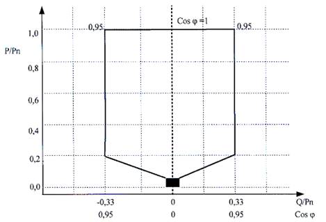
a) In cases where a power station generates an active power output more than or equal to 20% of the rated active power output and the voltage at the high voltage side of the step-up transformer of the power station is within the range of ± 10% of the nominal voltage, the power station must be capable of continuously adjusting reactive power output within a power factor range from 0.95 (corresponding to the reactive power output mode) to 0.95 (corresponding to the reactive power input mode) at the high voltage side of the step-up transformer of the power station or at the point of reactive power separation and measurement of each power station in the case of multiple power stations connected to or transmitting power through 01 step-up transformer corresponding to the rated power;
b) In cases where a power station generates an active power less than 20% of rated power, such power station may reduce ability to receive or generate reactive power in accordance with characteristics of the power station.
5. Reactive power and voltage control mode:
a) A wind power station or solar power station must be capable of controlling voltage and reactive power output in the following modes:
- Voltage control mode in accordance with voltage setpoint, voltage control mode in accordance with voltage regulation droop characteristic (voltage/reactive power relationship characteristic);
- Reactive power setting control mode;
- Power factor control mode.
b) If the voltage at the high voltage side of the power station’s step-up transformer is within the range of ± 10% of the nominal voltage, wind power stations and solar power stations shall be capable of regulating the voltage at the low voltage side of the step-up transformer with a deviation not exceeding ± 0.5% of the rated voltage (compared to the voltage setpoint) whenever the reactive power of the power station is still within the permissible operating band, and completing this for a duration of no more than 05 seconds.
6. A wind power station or solar power station, at any time they are connected to the grid, must be capable of maintaining generation of electricity corresponding to voltage bands at the high voltage side of the step-up transformer of the power station for the following durations:
![]()
![]()
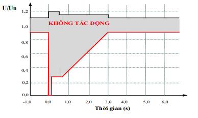
a) Voltage less than 0.3 pu, minimum time is 0.15 seconds;
b) Voltage from 0.3 pu to under 0.9 pu, minimum time is calculated in following formula:
Tmin = 4 x U – 0.6
Where:
- Tmin (in seconds): Minimum time to maintain power generation;
- U (pu): Actual voltage at the high voltage side of the step-up transformer of the power station calculated in pu (per-unit) values;
c) Voltage from 0.9 pu to under 1.1 pu, wind and solar power stations must maintain continuous generation;
d) Voltage from 1.1 pu to under 1.15 pu, wind and solar power stations must maintain generation for a duration of 03 seconds;
dd) Voltage from 1.15 pu to under 1.2 pu, wind and solar power stations must maintain generation for a duration of 0.5 seconds.
7. Phase imbalance, total harmonic distortion, and voltage flicker perceptibility caused by the wind power station or solar power station at the high voltage side of the step-up transformer of the power station shall not exceed the values prescribed in Article 7, Article 8, and Article 9 of this Circular.
8. Wind power stations and solar power stations shall invest in equipment, control and automation systems ensuring stable, reliable, and secure connection with the Automatic Generation Control (AGC) system of the National Load Dispatch Authority for the purpose of remote control of stations’ power output in accordance with dispatch instructions from the National Load Dispatch Authority.
9. A wind power station or solar power station must maintain connection to the grid when the rate of change of frequency of the power system is within the band from 0 Hz/second to 01 Hz/second, as measured over a 500-millisecond time window.
10. When the voltage at the high voltage side of the power station’s step-up transformer is outside the range of ± 10% of the nominal voltage, the power station shall be capable of establishing a priority mode for injecting reactive current (when voltage is low) or absorbing reactive current (when voltage is high) to support the power system during contingencies; the reactive current shall be capable of changing from 0% to 10% of the power station’s rated voltage for each 01% change in voltage with a tolerance not exceeding 20% (rate of change determined by calculation by the Dispatch Authority in control), and the response completion duration shall be no later than 100 milliseconds.
11. After a contingency is cleared and the power system returns to normal operating mode, the power station must ensure:
a) The power station must be capable of restoring an active power output to return to its operating mode before the contingency with an active power output increase rate of not less than 30% of the rated power per 01 second and not more than 200% of the rated power per 01 second;
b) In cases where wind turbine generating sets or inverters of the solar power station are stopped from operation when the power system contingency persists longer than the minimum required grid connection time, the re-synchronization process of these generating sets must not occur earlier than 03 minutes after the power system returns to normal operating mode and the active power output recovery rate is not more than 10% of the rated power per 01 minute.
12. The power station must maintain connection to the grid when the voltage at the high voltage side of the step-up transformer of the power station experiences instantaneous voltage phase angle oscillations (Phase Swing) up to 20 degrees within a timeframe of 100 milliseconds without interruption of power generation or decrease in active power output.
13. Wind power stations and solar power stations connected to the electrical grid at a voltage level of 110 kV or higher shall be equipped with a fault recording monitoring system with GPS (Global Positioning System) time synchronization functionality and a power quality monitoring system, and connect these systems to the Dispatch Authority in control.
14. Wind power stations and solar power stations shall be equipped with monitoring and data acquisition devices for meteorological and primary energy data, ensuring stable, reliable, secure connection, and continuously sending data to the Dispatch Authority in control.
Article 41. Requirements for wind power stations and solar power stations with a capacity from above 1 MW to 30 MW connected to the distribution grid at medium voltage level or higher
1. Wind and solar power stations must be capable of maintaining generation of active power in the following modes:
a) Unrestricted generation mode: Generate the maximum possible power output based on the variability of the primary energy source (wind or solar);
b) Power output control mode:
A wind power station or solar power station must be capable of limiting their power output in accordance with dispatch instructions in the following cases:
- In cases where the variable primary energy is lower than the limit value set by the dispatch instruction, the generation output shall be the maximum possible;
- In cases where the variable primary energy is equal to or greater than the limit value set by the dispatch instruction, the generation output shall be equal to the limit value set by the dispatch instruction within a tolerance band of ± 01% of the rated power.
2. Wind and solar power stations, at all times when connected to the grid, must be capable of maintaining generation of electricity for minimum durations corresponding to the operating frequency bands prescribed in Table 12 as follows:
Table 12
Minimum durations for which the generation of electricity is maintained corresponding to the frequency bands of the power system
Frequency band of the power system | Minimum duration of maintenance |
From 47.5 Hz to 48.0 Hz | 10 minutes |
From over 48 Hz to under 49 Hz | 30 minutes |
From 49 Hz to 51 Hz | Continuous generation |
From over 51 Hz to 51.5 Hz | 30 minutes |
From over 51.5 Hz to 52 Hz | 01 minutes |
3. When the power system frequency is more than 50.5 Hz, a wind power station or solar power station must be capable of reducing the active power output in accordance with the relative slope of the static droop characteristics in the range from 02% to 10%. The setting value of the relative slope of the static droop characteristics shall be calculated and determined by the Dispatch Authority in control. This active power output reduction process must begin to decrease no later than 02 seconds upon recording a frequency above 50.5 Hz and must be completed within 15 seconds.
4. A wind power station or solar power station must be capable of adjusting the reactive power output in accordance with the characteristics as depicted in the figure below and described at Point a and Point b of this Clause:
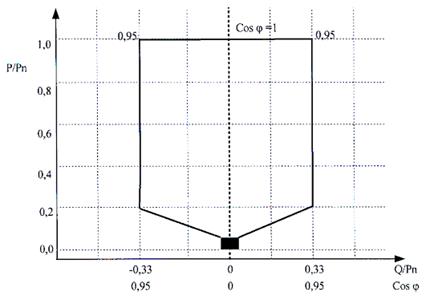
a) In cases where a power station generates an active power output more than or equal to 20% of the rated active power output and the voltage at the high voltage side of the step-up transformer of the power station is within the range of ± 10% of the nominal voltage, the power station must be capable of continuously adjusting reactive power output within a power factor range from 0.95 (corresponding to the reactive power output mode) to 0.95 (corresponding to the reactive power input mode) at the high voltage side of the step-up transformer of the power station or at the point of reactive power separation and measurement of each power station in the case of multiple power stations connected to or transmitting power through 01 step-up transformer corresponding to the rated power;
b) In cases where a power station generates an active power less than 20% of rated power, such power station may reduce ability to receive or generate reactive power in accordance with characteristics of the power station.
5. Reactive power and voltage control mode:
a) A wind power station or solar power station must be capable of controlling voltage and reactive power output in the following modes:
- Voltage control mode in accordance with voltage setpoint, voltage regulation droop characteristic (voltage/reactive power relationship characteristic);
- Reactive power setting control mode;
- Power factor control mode;
b) If the voltage at the high voltage side of the power station’s step-up transformer is within the range of ± 10% of the nominal voltage, wind power stations and solar power stations shall be capable of regulating the voltage at the low voltage side of the step-up transformer with a deviation not exceeding ± 0.5% of the rated voltage (compared to the voltage setpoint) whenever the reactive power of the generating set is still within the permissible operating band, and completing this for a duration of no more than 05 seconds.
6. A wind power station or solar power station, at any time they are connected to the grid, must be capable of maintaining generation of electricity corresponding to voltage bands at the high voltage side of the step-up transformer of the power station for the following durations:
![]()
![]()
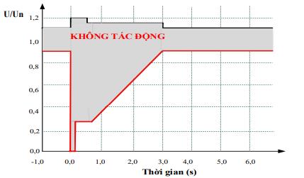
a) Voltage less than 0.3 pu, minimum time is 0.15 seconds;
b) Voltage from 0.3 pu to under 0.9 pu, minimum time is calculated in following formula:
Tmin = 4 x U – 0.6
Where:
- Tmin (in seconds): Minimum time to maintain power generation;
- U (pu): Actual voltage at the high voltage side of the step-up transformer of the power station calculated in pu (per-unit) values;
c) Voltage from 0.9 pu to under 1.1 pu, wind and solar power stations must maintain continuous generation;
d) Voltage from 1.1 pu to under 1.15 pu, wind and solar power stations must maintain generation for a duration of 03 seconds;
dd) Voltage from 1.15 pu to under 1.2 pu, wind and solar power stations must maintain generation for a duration of 0.5 seconds.
7. Phase imbalance, total harmonic distortion, and voltage flicker perceptibility caused by the wind power station or solar power station at the high voltage side of the step-up transformer of the power station shall not exceed the values prescribed in Article 6, Article 7, and Article 8 of this Circular.
8. Wind power stations and solar power stations shall invest in equipment, control systems, and automation ensuring stable, reliable, and secure connection with the Automatic Generation Control (AGC) system of the Dispatch Authority in control for the purpose of remote control of stations’ power output in accordance with dispatch instructions from the Dispatch Authority in control.
9. A wind power station or solar power station must maintain connection to the grid when the rate of change of frequency of the power system is within the band from 0 Hz/second to 01 Hz/second, as measured over a 500-millisecond time window.
10. When the voltage at the high voltage side of the power station’s step-up transformer is outside the range of ± 10% of the nominal voltage, the power station shall be capable of establishing a priority mode for injecting reactive current (when voltage is low) or absorbing reactive current (when voltage is high) to support the power system during contingencies; the reactive current shall be capable of changing from 0% to 10% of the power station’s rated current for each 01% change in voltage with a tolerance not exceeding 20% (rate of change determined by calculation by the Dispatch Authority in control), and the response completion duration shall be no later than 100 milliseconds.
11. After a contingency is cleared and the power system returns to normal operating mode, the power station must ensure:
a) The power station must be capable of restoring an active power output to return to its operating mode before the contingency with an active power output increase rate of not less than 30% of the rated power per 01 second and not more than 200% of the rated power per 01 second;
b) In cases where wind turbine generating sets or inverters of the solar power station are stopped from operation when the power system contingency persists longer than the minimum required grid connection time, the re-synchronization process of these generating sets must not occur earlier than 03 minutes after the power system returns to normal operating mode and the active power output recovery rate is not more than 10% of the rated power per 01 minute.
12. The power station must maintain connection to the grid when the voltage at the high voltage side of the step-up transformer of the power station experiences instantaneous voltage phase angle oscillations (Phase Swing) up to 20 degrees within a timeframe of 100 milliseconds without interruption of power generation or decrease in active power output.
Article 42. Requirements for solar and wind power sources with a capacity of 01 MW or less connected to the distribution grid at medium voltage level or higher
1. At all times when connected to the grid, solar and wind power sources shall be capable of maintaining generation of electricity for minimum durations corresponding to the operating frequency bands as prescribed in Table 13 as follows:
Table 13
Minimum durations for which the generation of electricity is maintained corresponding to the frequency bands of the power system
Frequency band of the power system | Minimum duration of maintenance |
From 48 Hz to under 49 Hz | 30 minutes |
From 49 Hz to 51 Hz | Continuous generation |
From over 51 Hz to 51.5 Hz | 30 minutes |
2. When the power system frequency is greater than 50.5 Hz, the active power of the solar or wind power source shall be reduced using the following formula:
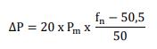
Where:
- ΔP: Reduction of active power output (MW);
- Pm: Active power at the time before conducting power reduction (MW);
- fn: Frequency of the power system before conducting power reduction (Hz).
3. Solar and wind power sources shall be capable of maintaining continuous generation of electricity within the voltage bands at the point of connection as prescribed in Table 14 as follows:
Table 14.
Minimum durations for which the generation of electricity is maintained corresponding to the voltage bands at the point of connection
Voltage at the point of connection | Minimum duration of maintenance |
Less than 50% of nominal voltage | Not required |
From 50% to under 85% of nominal voltage | 02 seconds |
From 85% to 110% of nominal voltage | Continuous operation |
From above 110% to 120% of nominal voltage | 02 seconds |
Above 120% of nominal voltage | Not required |
4. Solar and wind power sources shall not cause the injection of direct current into the distribution grid exceeding 0.5% of the rated current at the point of connection.
5. Solar and wind power sources shall comply with the regulations on voltage, phase balance, harmonics, voltage flicker perceptibility, and neutral earthing mode prescribed in Article 6, Article 7, Article 8, Article 9, and Article 11 of this Circular.
6. A solar or wind power source shall be equipped with protective devices that must:
a) Automatically disconnect from the distribution grid upon occurrence of an internal contingency within the solar or wind power source;
b) Automatically disconnect in case of a power outage from the distribution grid and not generate power to the grid when the distribution grid is experiencing a power outage;
c) Not automatically reconnect to the electrical grid unless the following conditions are met:
- The frequency of the electrical grid is maintained within the band from 48Hz to 51Hz for a minimum duration of 60 seconds;
- The voltage of all phases at the point of connection remains within the range from 85% to 110% of the rated voltage for a minimum duration of 60 seconds;
d) The customer requesting connection shall agree upon the requirements for the protection system with the Distribution System Operator, but shall at least include the protections prescribed at Point a, Point b, and Point c of this Clause, overvoltage and undervoltage protection, and frequency protection.
7. In addition to the requirements prescribed from Clause 1 to Clause 6 of this Article, solar and wind power sources with a capacity from 100 kW to 1 MW connected to the medium voltage grid shall satisfy the following technical requirements:
a) They shall ensure the reactive power control mode is activated in accordance with the power factor control mode with the power factor value (cosφ) set in accordance with the requirements of the Dispatch Authority in control, unless otherwise agreed upon with the Dispatch Authority in control;
b) They shall be capable of establishing a priority mode for injecting active power or reactive power as required by the Dispatch Authority in control when the voltage at the point of connection is outside the required band for continuous operation prescribed in Clause 3 of this Article.
8. The project owner of the solar or wind power source connected to the medium voltage grid with a capacity from 100 kW to 1 MW shall be responsible for agreeing with the Distribution System Operator upon the equipment, means of connection to the acquisition, monitoring, and control system of the Distribution Dispatch Authority.
Article 43. Requirements for the solar power system connected to the distribution grid at low-voltage level
The solar power system connected to the low-voltage grid should satisfy the following requirements:
1. Connection capacity
a) The total installed capacity of the solar power system connected at the low voltage level of a low voltage substation shall not exceed the installed capacity of such substation;
b) Solar power systems with a capacity of below 20 kWp shall be connected to the 01-phase or 03-phase electrical grid in accordance with the agreement with the Distribution System Operator;
c) The solar power system with a capacity of 20 kWp or higher shall be connected to the 03-phase electrical grid.
2. At all times when connected to the grid, solar power systems permitted to connect to the low voltage grid shall be capable of maintaining generation of electricity for minimum durations corresponding to operating frequency bands as prescribed in Table 15 as follows:
Table 15
Minimum durations for which the generation of electricity is maintained corresponding to the frequency bands of the power system
Frequency band of the power system | Minimum duration of maintenance |
From 48 Hz to 49 Hz | 30 minutes |
From 49 Hz to 51 Hz | Continuous generation |
From 51 Hz to 51.5 Hz | 30 minutes |
3. When the power system frequency is greater than 50.5 Hz, the active power of a solar power system with a capacity of 20 kWp or higher shall be reduced using the following formula:
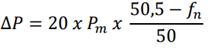
Where:
- ΔP: Reduction of active power output (MW);
- Pm: Active power at the time before conducting power reduction (MW);
- fn: Frequency of the power system before conducting power reduction (Hz).
4. Solar power systems shall be capable of maintaining continuous generation of electricity within the voltage bands at the point of connection as prescribed in Table 16 as follows:
Table 16
Minimum durations for which the generation of electricity is maintained corresponding to the voltage bands at the point of connection
Voltage at the point of connection | Minimum duration of maintenance |
Less than 50% of nominal voltage | Not required |
Between 50% and 85% of nominal voltage | 2 seconds |
Between 85% and 110% of nominal voltage | Continuous operation |
Between 110% and 120% of nominal voltage | 2 seconds |
Above 120% of nominal voltage | Not required |
5. Solar power systems connected to the low voltage grid shall not inject reactive power to the electrical grid and shall operate in reactive power absorption mode with a power factor (cosϕ) greater than 0.98.
6. Solar power systems shall not cause the injection of direct current into the distribution grid exceeding 0.5% of the rated current at the point of connection.
7. Solar power systems connected to the low voltage grid shall comply with the regulations on voltage, phase balance, harmonics, voltage flicker perceptibility, and neutral earthing mode prescribed in Article 6, Article 7, Article 8, Article 9, and Article 11 of this Circular.
8. A solar system shall be equipped with protective devices that must:
a) Automatically disconnect from the distribution grid upon occurrence of an internal contingency within the solar power system;
b) Automatically disconnect in case of a power outage from the distribution grid and not generate power to the grid when the distribution grid is experiencing a power outage;
c) Not automatically reconnect to the electrical grid unless the following conditions are met:
- The frequency of the electrical grid is maintained within the band from 48Hz to 51Hz for a minimum duration of 60 seconds;
- The voltage of all phases at the point of connection remains within the range from 85% to 110% of the rated voltage for a minimum duration of 60 seconds.
d) For solar power systems connected to the 03-phase low voltage grid, the customer requesting connection shall agree upon the requirements for the protection system with the Distribution System Operator, but shall at least include the protections prescribed at Point a, Point b, and Point c of this Clause, overvoltage and undervoltage protection, and frequency protection.
Section 5
TECHNICAL REQUIREMENTS FOR BATTERY ENERGY STORAGE SYSTEM
Article 44. Technical requirements for battery energy storage system
1. The battery energy storage system, at all times when connected to the grid, shall be capable of maintaining generation of electricity op for the minimum duration corresponding to the operating frequency bands as prescribed in Table 17 as follows:
Table 17
Minimum time for maintaining generation of electricity operation of the battery energy storage system corresponding to the frequency bands of the power system
Frequency band of the power system | Minimum duration of maintenance |
From 47.5 Hz to 48.0 Hz | 10 minutes |
From over 48 Hz to under 49 Hz | 30 minutes |
From 49 Hz to 51 Hz | Continuous generation |
From over 51 Hz to 51.5 Hz | 30 minutes |
From over 51.5 Hz to 52 Hz | 01 minutes |
2. A battery energy storage system, at all times when connected to the grid, shall maintain operation when the rate of change of frequency (RoCoF) of the system is within the band from 0 Hz/second to 01 Hz/second, as measured over a 500-millisecond time window.
3. The battery energy storage system, at all times when connected to the grid, shall maintain operation corresponding to the voltage bands at the point of connection for the specific durations as follows:
a) For voltage below 0.3 pu, the battery energy storage system shall inject maximum reactive current within permissible limits to support voltage stability and maintain operation for a minimum duration of 0.15 seconds;
b) For voltage from 0.3 pu to below 0.9 pu, the battery energy storage system shall inject reactive current within permissible limits to support voltage stability; the minimum duration of operation shall be calculated by the following formula:
Tmin = 4xU-0.6
Where: Tmin (seconds) is the minimum duration of generation of electricity; U(pu) is the actual voltage at the point of connection in per unit;
c) For voltages from 0.9 pu to below 1.1 pu, the battery energy storage system shall maintain continuous operation;
d) For voltage from 1.1 pu to below 1.15 pu, the battery energy storage system shall maintain generation of electricity for a duration of 03 seconds.
e) For voltage from 1.15 pu to 1.2 pu, the battery energy storage system shall maintain generation of electricity for a duration of 0.5 seconds.
f) When the voltage at the point of connection is restored to the normal operating band, for a duration of no more than 5 seconds, the battery energy storage system, if operating within the power system, shall restore normal operation.
g) When the voltage at the point of connection is restored to the normal operating band, if another contingency occurs causing a voltage sag 1.5 seconds later, the subsequent contingency shall be considered a new contingency.
4. The battery energy storage system shall be designed to maintain operation when experiencing instantaneous voltage phase angle jumps up to 20 degrees for a duration of 100 milliseconds.
5. Battery energy storage systems with a capacity of 10 MW or higher connected to the power system shall be capable of fast fault current support when a short-circuit occurs, specifically as follows:
a) The Battery Energy Storage System shall output maximum reactive current.
b) It is required to reach the maximum reactive current within 60-80 milliseconds.
c) The battery energy storage system shall be set to activate the fast fault current support feature when the phase voltage at the point of connection falls below 0.85pu and deactivate this feature when the phase voltage at the point of connection restores to 0.9pu.
6. The battery energy storage system shall be capable of restoring active power following a contingency, specifically:
a) After the contingency is cleared, the battery energy storage system, if operating within the power system, shall restore the active power to the pre-contingency setpoint value for a duration of no more than 5 seconds with a tolerance within ±5% of the setpoint value.
b) The rate of change of active power per second of the battery energy storage system in this case shall not be less than 30% of the rated power and not greater than 200% of the rated power of the battery energy storage system (30%Pđm/s ≤ RoC ≤200%Pđm/s).
7. Active power control mode
- In active power control mode, the battery energy storage system shall be capable of maintaining the active power delivered to or absorbed from the high voltage side of the step-up transformer of the battery energy storage system or at the point of power separation and measurement of the battery energy storage system, in cases where multiple power stations connect to 01 step-up transformer, in accordance with the set value, independent of frequency changes, unless the frequency control mode is activated.
- The active power control tolerance of the battery energy storage system shall be within the range of ±1% of the rated power (but no less than 0.5 MW).
- The rate of change of active power per minute of the battery energy storage system shall not be less than 1% of the rated power and not greater than 20% of the rated power.
8. Frequency control mode
In frequency control mode, the battery energy storage system shall be capable of changing active power corresponding to frequency changes in the following modes:
a) Primary frequency control mode
- Battery energy storage systems with a capacity of 3 MW or higher connected to the national power system shall be capable of engaging in the primary frequency control process bidirectionally delivering or absorbing active power.
- The deadband of the frequency control system of the battery energy storage system shall be adjustable with a minimum value of ± 0.05 Hz and a minimum setting resolution of 0.05 Hz.
- Droop of the static characteristic curve within the range from 2% to 10%. The settings for the deadband and the droop of the static characteristic curve shall be calculated and determined by the National Load Dispatch Authority.
- The maximum range of active power change shall cover up to 100% of the rated power of the battery energy storage system. The low frequency response process shall begin no later than 2 seconds from the time of detecting the frequency outside the deadband and shall be completed within 15 seconds.
b) Secondary frequency control mode
Battery energy storage systems with a capacity of 10 MW or higher connected to the national power system shall be capable of engaging in the secondary frequency control process bidirectionally delivering and absorbing active power. The response duration for secondary frequency control power shall not be more than 20 seconds from the time the control signal is received from the Dispatch Authority in control.
9. Reactive power control mode and voltage control mode
a) Reactive power adjustment range
The battery energy storage system shall be capable of adjusting reactive power equal to or better than the characteristic illustrated as follows:
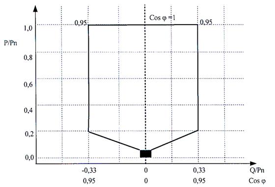
- In cases where the battery energy storage system is injecting or absorbing active power greater than or equal to 20% of the rated active power and the voltage at the high voltage side of the step-up transformer of the battery energy storage system or at the point of reactive power separation and measurement of the battery energy storage system corresponding to the rated power, in cases where multiple power stations connect to 01 step-up transformer, is within the range of ±10% of the nominal voltage, the battery energy storage system shall be capable of continuously adjusting reactive power within a power factor range of 0.95 or lower (corresponding to reactive power injection mode) to 0.95 or lower (corresponding to reactive power absorption mode) at the high voltage side of the step-up transformer of the battery energy storage system or at the point of reactive power separation and measurement of the battery energy storage system corresponding to the rated power in cases where multiple battery energy storage systems connect to 01 step-up transformer.
- In cases where the battery energy storage system is injecting or absorbing active power less than 20% of the rated power, the battery energy storage system may reduce its capability to absorb or deliver reactive power consistent with the characteristics of the battery energy storage system.
b) Voltage and reactive power control mode
- Battery energy storage systems shall come with reactive power control mode and power factor control mode.
- Battery energy storage systems with a capacity greater than 1MW shall come with voltage control mode.
10. The battery energy storage system shall not cause the injection of direct current at the point of connection exceeding 0.5% of the rated current.
11. Battery energy storage systems with a capacity of 30 MW or higher connected to the national power system shall be equipped with Power System Stabiliser (PSS) functionality capable of damping oscillations with frequencies within a band from 0.1 Hz to 5 Hz, whereby enhancing the stability of the power system. The project owner shall set and adjust the parameters of the PSS device to ensure that the PSS device has a damping ratio of no less than 5%.
12. Battery energy storage systems connected to the national power system at 110 kV or higher shall be equipped with a fault recording and monitoring system with GPS (Global Positioning System) time synchronization functionality and a PQ (Power Quality) monitoring system.
13. Battery energy storage systems connected to the electrical grid at a voltage level of 110 kV or higher or with a capacity of 10 MW or higher shall be equipped with an information system and ensure this system is compatibly connected with the information system of the grid operating entity and the Dispatch Authority in control, ensuring communication and data transmission (including data from SCADA systems, PMUs, and fault recording monitoring) are complete, reliable, and continuous the purpose of operating the power system and the electricity market. The minimum means of communication for the purpose of dispatch and operation, including direct channels and telephone, shall operate reliably and continuously.
14. Battery Energy Storage Systems connected to the national power system at the voltage level of 110 kV or higher shall invest in equipment, control systems, and automation ensuring stable, reliable, and secure connection with the Automatic Generation Control (AGC) system of the National Load Dispatch Authority for the purpose of remote control of power output in accordance with dispatch instructions from the National Load Dispatch Authority.
15. For BESS installed within Renewable Energy (RE) power stations, the power station shall equip remote control functionality for the setpoint of the total power exchanged with the electrical grid of the entire power station, including the capacity of both the RE source and the BESS.
16. The project owner of the battery energy storage system shall be responsible for investing in, installing, managing, and operating the information system within their management scope. The operator of the battery energy storage system may agree to use the information system of the system operator or that of other providers to connect to the information system of the Dispatch Authority in control to ensure continuous and reliable information for the purpose of operating the power system and the electricity market.
17. Regarding the protection of the battery energy storage system
Battery energy storage systems connected to the electrical grid at a voltage level of 110 kV or higher or with a capacity of 10 MW or higher shall be equipped with a protection system:
a) The protection system shall have the configuration, protection functions, and necessary setting parameters to ensure the battery energy storage system is protected from contingencies occurring within the battery energy storage system and contingencies on the electrical grid.
b) The protection system for the battery energy storage system with a capacity above 10 MW shall have emergency control functionality for active power according to pre-settings. Specific settings shall be calculated and prescribed by the Dispatch Authority in control. Emergency active power control shall ensure a deviation not exceeding 1% from the power factor setpoint for a duration of 1 minute.
c) The project owner of the battery energy storage system shall be responsible for setting and configuring the necessary protection functions and setting parameters for the battery energy storage system to protect the devices and elements within the battery energy storage system. The settings for the protection system of the battery energy storage system shall ensure that the battery energy storage system maintains the minimum operating duration as prescribed and satisfies the requirements in this Circular.
d) The Dispatch Authority in control is entitled to change the setting parameters of the protection system of the battery energy storage system to align with the operating conditions of the power system; however, this must not cause damage or harm to the devices and elements within the battery energy storage system.
Section 6
PROCEDURES FOR CONNECTION AGREEMENT
Article 45. Sequence of procedures for agreeing on connection to the transmission system
1. When wishing to establish a new connection or to change an existing point of connection, the customer who wishes to connect shall send the dossier of request for connection to the Transmission System Operator.
2. A dossier of request for connection shall comprise of:
a) A written request for connection, with the attachments as prescribed in the form provided in the Appendix to this Circular;
b) Technical documentation regarding the devices planned for connection or the planned changes at the existing point of connection;
c) Scheduled project completion, economic and technical data for the new connection project or the change to the existing connection.
3. After receiving a complete and valid dossier of request for connection, the Transmission System Operator shall:
a) Consider the compatibility with the electricity development plan approved by the competent State regulatory authorities, the requirements related to the electrical devices expected at the point of connection;
b) Assume the prime responsibility for performing the assessment of the impacts of connecting the equipment, grid, or power station of the customer who wishes to connect on the transmission grid, including the following main details:
- Calculation of steady state for the regional electrical grid where connection is requested for the next 10-year period, including calculations for scenarios and assessment of the capability to satisfy the N-1 criterion for the regional transmission grid;
- Calculation and assessment of short-circuit currents at the points of connection and the regional electrical grid for the next 10-year period;
- Specific determination of constraints and limitations due to the new connection that may affect the safe and stable operation of the transmission system;
- Assessment of the capability to satisfy the requirements for the operation of the power system prescribed in Chapter II of this Circular, and the technical requirements at the point of connection prescribed in this Chapter.
c) A draft Connection Agreement made using the form provided in the Appendix to this Circular, sent to the customer who wishes to connect and the Dispatch Authority in control;
d) No later than 15 working days from the date of receipt of the complete and valid dossier of request for connection from the customer, send written requests to the Dispatch Authority in control and relevant entities for their official comments on the following main details:
- Assessment of the impacts of the connection on the transmission system;
- Details related to technical requirements for connecting electrical equipment, requirements for the purpose of operation and dispatch for generating sets, requirements for equipping contingency-based load shedding systems, generation shedding, interlocking for electricity customers to ensure satisfaction of the operational and technical requirements prescribed in Chapter II and Chapter V of this Circular;
- A draft Connection Agreement with the details prescribed in the Appendix to this Circular.
4. The Dispatch Authority in control shall be responsible for coordinating with the Transmission System Operator in performing the assessment of the impacts of the connection on the transmission system in accordance with Point b, Clause 3 of this Article and provide comments on and supplements to the draft Connection Agreement prescribed at Point d, Clause 3 of this Article.
5. The customer who wishes to connect shall be responsible for fully providing other necessary information to the Transmission System Operator and the Dispatch Authority in control to determine other necessary technical characteristics and technical requirements ensuring the safe, stable, and reliable operation of the transmission system.
6. Within a time limit of 20 working days from the date of receipt of the request from the Transmission System Operator, the Dispatch Authority in control and relevant entities shall be responsible for sending comments in writing regarding the details prescribed at Point d, Clause 3 and Clause 4 of this Article to the Transmission System Operator.
7. After receiving comments from the Dispatch Authority in control and other relevant entities, the Transmission System Operator shall be responsible for finalizing the draft Connection Agreement, reaching unanimous agreement with the customer who wishes to connect on the technical requirements at the point of connection, and jointly signing the Connection Agreement with the customer.
8. The Connection Agreement shall be made into 04 counterparts, of which each party keeps 02. Within a time limit of 05 working days from the date the Connection Agreement has been executed, the Transmission System Operator shall be responsible for sending 01 copy of the executed Connection Agreement (including its appendices) to the Dispatch Authority in control, and relevant entities for coordination during the process of investment and construction, energization for commissioning, and official operation.
9. The timeframe for reviewing the dossier of request for connection, agreeing on related details, and executing the Connection Agreement shall comply with Article 47 of this Circular.
10. In cases where a customer wishes to connect to the grid or equipment of another Transmission Grid User, the customer who wishes to connect shall be responsible for reaching agreement directly with such Transmission Grid User. Before reaching unanimous agreement with the customer who wishes to connect on the connection plan, the Transmission Grid User owning the equipment shall be responsible for coordinating with the Transmission System Operator and the Dispatch Authority in control to ensure the equipment of the customer who wishes to connect fully satisfies the technical requirements for equipment at the point of connection prescribed in this Circular. Regarding new details related to the new connection with the customer who wishes to connect, the Transmission Grid User shall be responsible for updating such details in the Connection Agreement executed with the Transmission System Operator.
11. In cases of connection to the 110 kV or medium voltage busbar at 500 kV or 220 kV substations within the management scope of the Transmission System Operator, the connection agreement sequence and procedures shall comply with the regulations prescribed from Clause 1 to Clause 9 of this Article.
Article 46. Sequence of procedures for agreeing on connection to the distribution system
1. In cases of connection to the 03-phase low voltage grid, when wishing to establish a new connection to the distribution grid or to change an existing connection, the Distribution Grid User shall send to the Distribution System Operator the documents prescribed in the Appendix to this Circular.
2. In cases of connection at medium voltage and 110 kV levels, when wishing to establish a new connection or to change an existing connection, the Distribution Grid User shall send to the Distribution System Operator the following documents:
a) Connection registration information corresponding to the connection request prescribed in the Appendices to this Circular;
b) Schematic diagram of the main electrical equipment beyond the point of connection;
c) Technical documentation regarding the devices planned for connection or the planned changes at the existing point of connection, scheduled project completion, and technical data for the new connection project or the change to the existing connection.
3. In cases where, at the time of preparing the dossier of request for connection to medium voltage and 110 kV levels, complete information and documents prescribed in Clause 13 of this Article are not yet available, the Distribution Grid User shall be responsible for agreeing with the Distribution System Operator regarding the provision of information and documents and clearly specify this in the Connection Agreement.
4. Upon receipt of the dossier of request for connection, the Distribution System Operator shall be responsible for checking and providing a written notice regarding the completeness and validity of the dossier.
5. After receiving the complete and valid dossier of request for connection, the Distribution System Operator shall:
a) Consider the compatibility with the electricity development plan approved by the competent State regulatory authorities, the requirements related to the electrical devices expected at the point of connection;
b) Assume the prime responsibility for assessing the impacts of connecting the equipment, grid, or power station of the customer requesting connection on the distribution grid regarding the loading capability of existing lines and substations; the impact on short-circuit current; the impact on power quality of the distribution grid after the connection is implemented; the coordination of protection systems;
c) Request comments from the Dispatch Authority in control and entities related to the connection regarding the impacts of the connection on the power system and the regional electrical grid, requirements for connection to the information system and the SCADA system of the Dispatch Authority in control, requirements for protective relays and automation, the electricity measurement plan, and details related to technical requirements for equipment at the point of connection;
d) Prepare and agree upon the single-line diagram including technical parameters of the devices and the layout diagram of the point of connection of the customer’s grid to the distribution grid, as the official diagram to be used in the Connection Agreement;
dd) Draft the Connection Agreement with the details prescribed in the Appendix to this Circular and send it to the customer requesting connection.
6. The customer requesting connection shall be responsible for providing to the Distribution System Operator the necessary information for the purpose of review and agreement on the implementation of the connection plan and the execution of the Connection Agreement with the Distribution System Operator.
7. The Connection Agreement shall be made into 04 counterparts, of which each party keeps 02. Within a time limit of 05 working days from the date the Connection Agreement has been executed, the Distribution System Operator shall be responsible for sending 01 copy of the executed Connection Agreement (including the appendices) to the Dispatch Authority in control, and relevant entities for coordination during the process of investment and construction, energization for commissioning, and official operation.
8. In cases where agreement cannot be reached on the connection plan, the Distribution System Operator shall be responsible for notifying the customer in writing and reporting to the Ministry of Industry and Trade regarding the reasons for not reaching agreement on the connection plan.
Article 47. Timeframe for reviewing and executing the connection agreement
1. The timeframe for carrying out steps of negotiation and execution of the Connection Agreement is prescribed in Table 18 as follows:
Table 18
Timeframe for reviewing and executing the connection agreement
Tasks | Timeframe | Responsible party |
Timeframe for negotiation and execution of the Connection Agreement on connection to the transmission grid | ||
Submit a valid and complete dossier of request for connection |
| The customer who wishes to connect |
Review the dossier of request for connection, prepare the draft Connection Agreement, and send it for comments from relevant entities | No more than 35 working days from the date of receiving a complete and valid dossier | The Transmission System Operator shall assume the prime responsibility and coordinate with the Dispatch Authority in control and relevant entities |
Finalize the draft Connection Agreement, reach a unanimous agreement and execute the Connection Agreement | No more than 20 working days from the date of receiving comments from relevant entities | The Transmission System Operator and the customer who wishes to connect |
Timeframe for reviewing and executing the Connection Agreement with the Distribution Grid User requesting connection at the voltage level of 110 kV and the customer owning a generating set requesting connection to the medium voltage grid | ||
Submit a dossier of request for connection |
| The customer requesting connection |
Review the dossier of request for connection | No more than 15 working days | The Distribution System Operator, the Dispatch Authority in control |
Prepare the draft Connection Agreement | No more than 03 working days | The Distribution System Operator |
Negotiate and execute the Connection Agreement | No more than 07 working days | The Transmission System Operator and the customer requesting connection |
2. For electricity customers with their own substations connecting to the medium voltage grid: Within a time limit of 02 working days from the date of receipt of the complete and valid dossier from the customer, the Distribution System Operator shall be responsible for conducting a site survey, reaching agreement, and signing the Connection Agreement with such customer.
Section 7
IMPLEMENTATION OF THE CONNECTION AGREEMENT ON THE TRANSMISSION GRID
Article 48. Rights to get access to devices at points of connection
1. The Transmission System Operator and the customer who wishes to connect shall have the rights to get access to the devices at points of connection during the survey process to make plans for connection, construction, installation, testing, replacement, removal, operation and maintenance of connected devices.
2. The Transmission System Operator and the Grid User shall be responsible for facilitating the parties to exercise the rights prescribed in Clause 1 of this Article.
Article 49. Provision of a dossier for pre-energization check of the point of connection for the purpose of commissioning and acceptance testing on the transmission grid
1. A dossier for overall pre-energization check of the point of connection (technical documentation confirmed by the customer who wishes to connect and copies of legal documents certified as prescribed) shall comprise of:
a) Written records of partial and complete acceptance testing for the connected devices of the power station, line, and substation connected to the transmission grid, verifying their compliance with Vietnamese technical standards or international standards permitted for application in Vietnam and satisfaction of the technical requirements for connected devices prescribed in this Chapter.
b) Approved technical design documentation as well as amendments and supplements (if any) compared to the initial design, including the following documents:
- General description, layout plan of electrical devices;
- Main electrical connection diagram, single-line diagram of the electrical part fully showing the connected devices from medium voltage level upwards from the point of connection towards the customer’s side, draft equipment numbering diagram;
- Schematic diagrams and design of the protection, automation, and control systems clearly showing circuit breakers, current transformers, voltage transformers, surge arresters, disconnectors, interlocking logic circuits for switching operations based on circuit breaker state;
- Secondary circuit diagrams of the protection, automation, and control systems;
- Diagram showing details of the connection plan of the customer’s electrical facility to the transmission grid and the parameters of the connection line;
- Other relevant diagrams (if any).
c) Documents concerning technical parameters and operational management, including:
- Documents concerning technical parameters of installed devices, including the parameters of the connection lines.
- Documents concerning the primary energy system, technical documentation on the excitation system, governor, simulation models, and simulation guidelines for the excitation system, governor, PSS, Laplace transfer function diagrams along with settings (for new hydropower, thermal power, and gas turbine power stations);
- Documents concerning the primary energy system, technical documentation on transient stability calculation models (RMS and EMT) depicting the complete response of all devices, control modes, as well as the entire plant’s response at the point of connection, and manuals for using and operating such models on calculation software. The provided transient stability calculation model must be compatible with the existing infrastructure of the Dispatch Authority in control (for new wind and solar power stations).
- Protective relay and automation setting guidelines, specialized software for communication with and setting of protective relays, and protective relay settings from the point of connection towards the Customer’s facilities;
- Manufacturer’s equipment operation manuals and other relevant technical documents.
d) Startup calculation documents, commissioning plan; proposed plan for energization and operation.
2. Unless otherwise agreed upon, the customer who wishes to connect shall be responsible for fully providing the details and documents as prescribed at Point b, Point c, and Point d, Clause 1 of this Article to the Dispatch Authority in control and providing the documents prescribed at Points a, Point b, Point c, and Point d, Clause 1 of this Article to the Transmission System Operator for the purpose of preparation of the energization method within the following timeframe:
a) No later than 03 months before the scheduled date of initial trial run of the power station;
b) No later than 02 months before the scheduled date of initial trial run of the power station.
3. Based on the documentation provided by the customer who wishes to connect, the Dispatch Authority in control shall be responsible for preparing the energization method for putting the new facility into operation to ensure the safety and reliability of equipment within the national power system. The customer who wishes to connect shall be responsible for cooperating with the Dispatch Authority in control in developing the energization method.
4. No later than 20 working days from the date of receipt of the complete documentation, the Dispatch Authority in control shall be responsible for sending to the customer who wishes to connect the following documents:
a) Device numbering diagram after being agreed upon with the customer who wishes to connect;
b) Requirements for the settings of protective relays and automation of the customer from the point of connection towards the customer’s side; protective relay and automation setting sheets or the written approval of the settings related to the transmission grid for the protective relay and automation devices of the customer who wishes to connect;
c) Comments on the energization plan of the customer who wishes to connect;
d) Requirements for testing and calibration of devices;
dd) Requirements for establishing the communication system for purpose of dispatch work;
e) Requirements for connection and operation regarding the SCADA system, fault recorders, the PMU system, and the PSS;
g) Requirements for equipping the information technology system and other necessary infrastructure for the purpose of operation of the electricity market;
h) A list of relevant personnel and dispatchers along with their telephone numbers and methods for contact and information exchange.
5. No later than 20 working days before the date the point of connection is energized, the customer who wishes to connect must reach an agreement with the Dispatch Authority in control upon the commissioning schedule and the method for energization and operation of electrical equipment.
6. No later than 15 working days before the energization date of the point of connection, the customer who wishes to connect shall provide to the Transmission System Operator the following details:
a) The commissioning schedule and the method for energization and operation of electrical equipment agreed with the Dispatch Authority in control;
b) Agreement on the separation of responsibilities of each party regarding the management and operation of the connected devices;
c) Internal regulations on safe operation of connected devices;
d) A list of operating personnel who have been adequately trained and qualified in accordance with the Regulations on dispatch, operation, switching, contingency response, black start, and restoration of the national power system promulgated by the Minister of Industry and Trade, including their full name, professional title, responsibilities, phone number, and other means of contact.
7. No later than 15 working days before the energization date of the point of connection, the customer who wishes to connect shall provide to the Dispatch Authority in control the information prescribed at Point b, Point c, and Point d, Clause 6 of this Article and provide to the Electricity Wholesaler the information prescribed at Point a, Clause 6 of this Article.
Article 50. Pre-energization check of the point of connection for the purpose of commissioning and acceptance testing on the transmission grid
1. No later than 05 working days before the scheduled date for implementing the energization of the point of connection, the customer who wishes to connect and the Transmission System Operator shall perform a site check and acceptance testing of the point of connection.
2. The Transmission System Operator shall be responsible for agreeing with the customer who wishes to connect regarding the sequence of procedures for checking dossiers, written record of acceptance testing, and the actual installation of equipment in accordance with the Connection Agreement.
3. In cases where the Transmission System Operator notifies that the point of connection or the devices related to the point of connection of the customer who wishes to connect does not yet satisfy the conditions for energization, the customer shall be responsible for correcting, supplementing, or replacing the devices as required and reach an agreement again with the Transmission System Operator on the timing of the next check.
4. In cases where the Dispatch Authority in control warns that energization risks affecting the safe, stable, and reliable operation of the transmission system or the customer’s equipment, the customer shall be responsible for coordinating with the Dispatch Authority in control and the Transmission System Operator to re-check the matters related to the warning, agree upon a resolution plan, and reach an agreement again with the Transmission System Operator on the timing of the next check.
5. In cases where the customer who wishes to connect perceives that the energization of the electrical facility may potentially affect the stable and safe operation of the customer’s equipment, the customer shall be responsible for proposing to the relevant entities to coordinate in resolution and reach an agreement again with the Transmission System Operator on the timing of the next check.
6. The Transmission System Operator and the customer who wishes to connect shall sign the written record of pre-energization check of the point of connection.
7. After obtaining the written record of pre-energization check of the point of connection and confirmation that the conditions for energization are satisfied, the Transmission System Operator shall be responsible for providing written notices to the customer who wishes to connect and the Dispatch Authority in control regarding the official approval for energization of the electrical facility of the customer who wishes to connect, ensuring that the facility has been checked fully satisfying the technical requirements prescribed in the Connection Agreement, complying with this Circular, and being consistent with the power development master plan and the implementation plan for the master plan approved by the competent State regulatory authority.
Article 51. Energization of the point of connection for commissioning and acceptance testing
1. After receiving the written notice regarding the official approval for energization from the Transmission System Operator, the customer who wishes to connect shall be responsible for sending to the Dispatch Authority in control and the Transmission System Operator the written registration for energization of the point of connection, with the following documents attached thereto:
a) Documents confirming the facility has undergone all legal and technical procedures:
- Written confirmation from the project owner affirming that the devices within the scope of energization have been tested and checked, satisfying the operational and technical requirements at the point of connection and fully comply with the law regulations;
- The written notice of the official approval for energization from the Transmission System Operator;
- The written record of acceptance testing of the Measuring System, confirming qualification for energization for the purpose of commissioning and acceptance testing, including finalized readings of the electricity delivery meters;
- The executed Power Purchase Agreement or the agreement on electricity purchase;
b) Documents confirming the facility meets the conditions for operation and dispatch including:
- Primary devices numbered in accordance with the primary diagram issued by the Dispatch Authority in control;
- Protective relay and automation systems, control, excitation, and governor systems that have been set properly in accordance with the requirements prescribed in this Circular and those of the Dispatch Authority in control;
- A list of operating personnel who have been adequately trained and qualified in accordance with the Regulations on dispatch, operation, switching, contingency resolution, black start, and restoration of the national power system promulgated by the Minister of Industry and Trade, including their full name, professional title, responsibilities, phone number, and contact details;
- Dispatch information devices prescribed in the Regulations on dispatch, operation, switching, contingency resolution, black start, and restoration of the national power system promulgated by the Minister of Industry and Trade;
- Completed connection of information and signals fully with the SCADA system, the fault recording and monitoring system, the PMU system, and the information system of the Dispatch Authority in control as prescribed;
- Operation coordination procedure agreed between the generating set and the Dispatch Authority in control.
2. In cases where the energization of the customer’s point of connection affects the operating mode or requires equipment on the electrical grid to be taken out of operation, the Transmission System Operator shall be responsible for registering with the Dispatch Authority in control the plan for taking equipment out of service within its management scope to coordinate the energization of the point of connection.
3. Within a time limit of 05 working days from the date of receipt of the application, the Dispatch Authority in control shall be responsible for providing notices to the Transmission System Operator and the customer who wishes to connect to the transmission grid of the timing and method of energization of the point of connection.
4. The Transmission System Operator and the customer who wishes to connect shall be responsible for coordinating the implementation of the energization of the point of connection using the method notified by the Dispatch Authority in control.
Article 52. Commissioning, testing, acceptance testing for putting devices beyond the point of connection into operation
1. Minimum tests required to be performed for hydropower and thermal power stations after first-time energization:
a) Tests for the generating set include: test to measure the inertia constant of the entire rotating mass (including turbine, generator rotor, and exciter generator, if any); test of the generating set’s P-Q capability curve; open-circuit saturation characteristic measurement test; test to measure the reactance components and time constants of the generator (In cases where the power station can provide factory documents and manufacturer’s test reports that provide all the above parameters, the test to measure the reactance components and time constants of the generator is not required).
b) Tests for the excitation system include: reactive power rejection test, determining the gain and time constant of the AVR system; step response test when the generator is disconnected from the grid to evaluate the response capability of the AVR system; frequency response test of the excitation system when the generator is disconnected from the grid to check the stability of the AVR system; frequency response test of the excitation system when the generating set is connected to the grid and the PSS is not activated to check the excitation system transfer function; frequency response test of the excitation system when the generating set is connected to the grid and the PSS is activated to check the phase compensation of the PSS with the excitation system transfer function; test to check the gain margin of the PSS to determine the optimal gain of the PSS; frequency response test of the excitation system when the generating set is connected to the grid in cases with and without PSS activation to check the oscillation damping capability of the PSS for inter-region oscillations; step response test when the generating set is connected to the grid to check the effect of the PSS in damping local mode oscillations of the generating set; impulse test to check the generating set response to major contingencies on the system.
c) Tests for the governor system include: power step response test determining the response of the generating set governor system when there is a request to change generation output; test to determine the static factor of speed droop and primary frequency regulation; frequency response capability test.
d) SCADA, AGC, FRS/PQ/PMU connection tests.
2. Minimum tests required to be performed for wind power stations, solar power stations, and BESS after first-time energization, unless the primary energy source is unavailable for the tests prescribed at Point a, Point b, Point c, Point d, and Point dd:
a) Testing the capability to generate and receive reactive power.
b) Voltage control capability test.
c) Frequency response capability test.
d) SCADA, AGC, FRS/PQ/PMU connection tests.
dd) Power quality measurement test.
3. In addition to the tests prescribed in Clause 1 and Clause 2 of this Article, the customer who wishes to connect shall be responsible for performing other tests to satisfy the technical requirements agreed upon in the Connection Agreement and the Power Purchase Agreement.
4. The sequence of procedures for testing and supervision of tests regarding the details prescribed in Clause 1 and Clause 2 of this Article shall comply with the guidance procedures of the manufacturer and the guidance of the National Load Dispatch Authority.
5. During the period of commissioning, testing, acceptance testing for putting into operation the devices beyond the point of connection of the customer who wishes to connect, such customer shall assign operating personnel and authorized personnel on standby 24 hours a day and notify the list of personnel on standby along with their telephone numbers to the Transmission System Operator and the Dispatch Authority in control for contact when necessary.
6. During the process of commissioning, testing, acceptance testing, the customer who wishes to connect shall be responsible for coordinating with the Transmission System Operator, the Dispatch Authority in control, and other relevant entities to perform tests of the devices, ensuring compliance with the law regulations on testing, the Connection Agreement, and the executed Power Purchase Agreement, minimizing the impact of the new devices undergoing commissioning and acceptance testing on the safe and reliable operation of the national transmission system.
7. During the testing process, the Dispatch Authority in control shall be responsible for arranging a reasonable operating method, coordinating with and facilitating the customer who wishes to connect in performing tests following the approved testing schedule.
8. During the testing process, the electricity purchaser and the System Operator shall be responsible for coordinating with the Dispatch Authority in control, the customer who wishes to connect, and other relevant entities to supervise the testing process and confirm the test results, ensuring their compliance with the law regulations on testing, the Connection Agreement, and the executed Power Purchase Agreement.
9. Upon completion of the commissioning, testing, and acceptance testing process, the customer who wishes to connect shall be responsible for confirming and fully providing the following information to the Dispatch Authority in control and the Transmission System Operator:
a) Actual technical parameters of the electrical equipment, lines, substations, generating sets;
b) Test results and actual setting parameters of the equipment systems (excitation system, governor system, etc.) and the testing requirements agreed upon in the Connection Agreement, the Power Purchase Agreement (if any);
c) Other technical requirements that have been agreed upon in the Connection Agreement.
In cases where the devices of the customer who wishes to connect do not satisfy the requirements prescribed in this Circular and the executed Connection Agreement, the Transmission System Operator or the Dispatch Authority in control is entitled to temporarily disconnect or isolate the customer’s devices or grid from the transmission grid and request the customer who wishes to connect to implement supplementary and remedial measures.
10. The customer wishing to connect shall put the grid, power station, and electrical devices beyond the point of connection into operation only after obtaining all written records of testing, commissioning, and acceptance testing fully satisfying the requirements prescribed in this Circular and having the written acceptance for putting the facility into operation from the competent State regulatory authority. The customer who wishes to connect shall be responsible for notifying the Transmission System Operator and the Dispatch Authority in control of the time the facility is officially put into operation. For tests not yet performed due to the primary energy source being unavailable as prescribed at Point a, Point b, Point c, Point d, and Point dd of Clause 2 of this Article, the customer who wishes to connect shall complete them within a maximum time limit of 01 year from the date of first-time synchronization.
11. The National Load Dispatch Authority shall be responsible for organizing the development and issuance of detailed technical requirements regarding testing and supervision of testing, and reporting them to the Ministry of Industry and Trade before application.
Article 53. Checking and operational supervision of devices after being officially put into operation
1. During operation, the Transmission System Operator or the Dispatch Authority in control (hereinafter referred to as the party requesting additional checks) is entitled to request the Transmission Grid User to perform checks, tests, or supplementary tests on the devices within the customer’s management scope for the following purposes:
a) To check the compliance of the devices within the grid and power station and at the point of connection with the provisions of this Circular, technical regulations permitted for application in Vietnam, and the specific requirements in the executed Connection Agreement;
b) To check the compliance with the agreements in the Power Purchase Agreement and the executed Connection Agreement regarding the electrical equipment of the Transmission Grid User;
c) To assess the impacts of the grid and power station of the Transmission Grid User on the safe, stable, and reliable operation of the national power system;
d) To validate and re-adjust the technical parameters of the generating sets and grid of the Transmission Grid User for the purpose of calculations for safe, stable, and reliable operation of the national power system.
2. Costs for performing checks, tests, and supplementary tests shall be agreed upon by the two parties and prescribed in the Connection Agreement or the Power Purchase Agreement. In cases where it is not yet prescribed in the Connection Agreement or the Power Purchase Agreement, the following shall be implemented:
a) In cases where the check results indicate that the devices of the Transmission Grid User do not comply with this Circular and technical regulations applicable to the devices, the Transmission Grid User shall bear all costs of the checks and supplementary tests;
b) In cases where the check results detect no violations, the party requesting additional checks shall bear all costs of the checks and supplementary tests. For check requests as prescribed at Point c and Point d, Clause 1 of this Article, the Dispatch Authority in control shall report to and obtain permission from the Ministry of Industry and Trade before performing the check.
3. Before performing checks and supplementary tests on the electrical grid and electrical equipment of the Transmission Grid User, the party requesting additional checks shall notify the Transmission Grid User at least 15 days in advance regarding the details, timing, duration of the check, and the list of personnel engaged in the check. The Transmission Grid User shall be responsible for coordinating and facilitating the party requesting additional checks to perform the checks.
4. During the checking process, the party requesting additional checks is permitted to install monitoring and checking devices within the electrical grid and electrical equipment of the Transmission Grid User but must not affect the performance of the equipment and the safe operation of the power station, grid, and electrical equipment of the Transmission Grid User.
5. During operation, in cases where equipment of the Transmission Grid User at the point of connection gives rise to technical issues that do not ensure safe and reliable operation for the transmission system, the Dispatch Authority in control shall notify the Transmission Grid User and the Transmission System Operator about the risk of operation not ensuring safety for the transmission system and request a timeframe for remedying the technical issues causing unsafety. The Transmission Grid User shall implement remedial measures and perform re-testing to bring the equipment beyond the point of connection back into operation as prescribed in Article 52 of this Circular. In cases where, after the remedy period the technical issues still have not been resolved, the Dispatch Authority in control or the Transmission System Operator is entitled to disconnect the point of connection and notify the Transmission Grid User.
6. For each generating set, the Dispatch Authority in control may request the Electricity Producer to conduct tests at any time to verify one or a combination of operating characteristics that the Electricity Producer has registered, but shall not test a generating set more than 03 (three) times in 01 year, unless:
a) Test and check results indicate that one or more operating characteristics do not match the parameters that the Electricity Producer has declared;
b) The Dispatch Authority in control and the Electricity Producer do not agree on the operating characteristics of the generating set;
c) Testing and checking is conducted upon request of the Electricity Producer;
d) It is a fuel switching test.
7. The Electricity Producer is entitled to conduct checks and tests on its generating sets for the purpose of re-determining the operating characteristics of each generating set after repair, replacement, improvement, or reassembly. The timing of the tests shall be agreed upon with the Dispatch Authority in control.
8. The Electricity Producer shall be responsible for performing re-checking and re-testing for the excitation system and governor system of the generating set when overhauling the generating set or when replacing or upgrading the excitation or governor systems. After completing the tests, written notices shall be provided to the relevant parties regarding the test results, assessments, and necessary requirements or recommendations. The Dispatch Authority in control shall be responsible for checking and sending a written confirmation regarding whether the test results satisfy or do not satisfy the requirements for operation and dispatch as prescribed. In cases where any item does not satisfy the requirements as prescribed, the Dispatch Authority in control shall provide a written notice of the items that failed to satisfy the requirements so that the Counterparty can implement setting, correction/adjustment, and re-testing.
9. During operation, the Transmission Grid User shall be responsible for ensuring continuous connection and full transmission of SCADA signals, and connection of the information system from the Control Center, power station, or substation to the central SCADA system of the Dispatch Authority in control.
Article 54. Replacement of devices at points of connection
1. During operation, to ensure the safe, stable, and reliable operation of the transmission and distribution systems, the Dispatch Authority in control or the Transmission System Operator is entitled to request the Grid User to invest in, upgrade, replace, or adjust the settings of the devices at the point of connection and shall notify and agree with the customer before implementation.
2. In cases where the Grid User needs to replace or upgrade devices at the point of connection or install additional new electrical devices which may potentially affect the normal operating mode of the electrical grid, the Grid User shall provide written notice and agree with the Transmission System Operator regarding such changes. Within a time limit of 10 working days from the date of receipt of the written notice from the Grid User, the Transmission System Operator shall be responsible for replying in writing regarding the request to replace or upgrade equipment at the customer’s point of connection.
3. In cases where the proposal of the Grid User is not approved, the Transmission System Operator shall be responsible for notifying the Grid User the reasons for not approving the proposal or the necessary amendment or supplementation requirements for the new devices planned for change.
4. All replacement and supplementary devices at the point of connection shall undergo checking, testing, and acceptance testing following the procedures prescribed from Article 48 to Article 54 of this Circular. Details regarding upgrading, replacement, or adjustment of settings for devices at the point of connection shall be added to the executed Connection Agreement.
Section 8
IMPLEMENTATION OF CONNECTION FOR DISTRIBUTION GRID USERS
Article 55. Rights to get access to devices at points of connection
1. The Distribution System Operator and the customer who wishes to connect shall have the rights to get access to the devices at points of connection during the survey process to make plans for connection, construction, installation, testing, replacement, removal, operation and maintenance of connected devices.
2. The Distribution System Operator and the Grid User shall be responsible for facilitating the parties to exercise the rights prescribed in Clause 1 of this Article.
Article 56. Provision of a dossier for pre-energization check of the point of connection for the purpose of commissioning and acceptance testing for the customer of the distribution grid connected at the voltage level of 110 kV and the customer having generating set(s) connected at the medium voltage level
1. Before the scheduled date for energization of the point of connection, the customer requesting connection shall provide 01 (one) dossier to the Distribution System Operator and 01 (one) dossier to the Dispatch Authority in control for the overall pre-energization check of the point of connection (technical documentation confirmed by the customer requesting connection and copies of legal documents certified as prescribed) which shall comprise of:
a) Written records of partial and complete acceptance testing for the connecting equipment of the power station, line, and substation connected to the distribution grid, verifying their compliance with Vietnamese standards (TCVN) or international standards recognized by Vietnam and satisfaction of the technical requirements for connected devices prescribed in Section 2 of this Chapter;
b) Approved technical design documentation as well as amendments and supplements (if any) compared to the initial design, including the following documents:
- General description, layout plan of electrical devices;
- Main electrical connection diagram, primary single-line diagram of the electrical part, draft equipment numbering diagram;
- Schematic diagrams and design of the protection and control systems clearly showing circuit breakers, current transformers, voltage transformers, surge arresters, disconnectors, interlocking logic circuits for switching based on circuit breaker state;
- Other relevant diagrams (if any).
c) Documents concerning technical parameters and operational management, including:
- Technical parameters of installed devices, including parameters of the connection line;
- Technical documentation of the excitation system and governor system of the generating set;
- Manuals for setting protective relays and automation, specialized software for interfacing with and setting relays, the settings for protective relays from the point of connection towards the customer’s side;
- Manufacturer’s equipment operation manuals and other relevant technical documents.
d) Proposed commissioning plan, proposed solution for energization and operation.
2. Unless otherwise agreed upon, the customer requesting connection shall be responsible for fully providing the documents prescribed in Clause 1 of this Article within the following time limit:
a) No later than 02 months before the scheduled date of initial trial run of the power station;
b) No later than 01 month before the scheduled date for putting the line or substation into initial trial run (excluding the written record of complete acceptance testing for the line and substation).
3. Based on the documentation provided by the customer who wishes to connect, the Dispatch Authority in control shall be responsible for preparing the energization method for putting the new facility into operation to ensure the safety and reliability of equipment within the national power system. The customer who wishes to connect shall be responsible for cooperating with the Dispatch Authority in control in developing the energization method.
4. No later than 20 working days from the date of receipt of the complete documentation for the energization dossier of a generating set, or no later than 15 working days from the date of receipt of the complete documentation for the energization dossier of a line or substation, the Distribution System Operator and the Dispatch Authority in control shall be responsible for sending to the customer requesting connection the following documents:
a) Device numbering diagram after being agreed upon with the customer requesting connection;
b) Requirements for the protective relay settings of the Customer from the point of connection towards the Customer’s facilities; protective relay setting sheet and the settings related to the protective relays of the Customer requiring grid connection, issued or approved by the Dispatch Authority in control;
c) Requirements for testing, calibration of devices;
d) Requirements for methods of receiving dispatch instructions;
dd) Requirements for establishing the communication system for purpose of dispatch work;
e) Requirements for acquiring and transmitting data to the SCADA system (if any);
g) Automatic control method (if any);
h) Comments on the energization plan of the customer requesting connect;
i) A list of relevant personnel and Operating Personnel along with their telephone numbers and methods for contact and information exchange.
5. No later than 10 working days before the scheduled date for energization of the point of connection, the customer requesting connection shall provide to the Distribution System Operator and the Dispatch Authority in control the following details:
a) Commissioning schedule (for power stations) and method for energization and operation of electrical equipment;
b) Agreement on the separation of responsibilities of each party regarding the management and operation of the connected devices;
c) Internal regulations on safe operation of connected devices;
d) A list of the customer’s Operating Personnel including their full names, professional titles, responsibilities along with their telephone numbers and methods for contact and information exchange.
Article 57. Provision of a dossier for pre-energization check of the point of connection for the purpose of commissioning and acceptance testing for the Electricity Customer having their own substation connected to the medium-voltage grid
1. Before the scheduled date for energization of the point of connection, the customer requesting connection shall provide to the Distribution System Operator 01 (one) dossier for pre-energization check of the point of connection (technical documentation confirmed by the customer requesting connection and copies of legal documents certified as prescribed) which shall comprise of:
a) Approved technical design documentation and amendments or supplements (if any) compared to the initial design including general description, main electrical connection diagram, layout plan of electrical equipment, schematic diagrams of the protection and control systems, other relevant diagrams, and technical parameters of the main electrical equipment;
b) Manuals for operation and management of equipment from the manufacturer;
c) Written records of partial and complete acceptance testing for the connected devices of the line and substation connected to the distribution grid, verifying their compliance with Vietnamese standards (TCVN) or international standards recognized by Vietnam and satisfaction of the technical requirements for connected devices prescribed in Section 2 of this Chapter;
d) Proposed energization schedule for commissioning and operation.
2. After receiving the complete documentation, the Distribution System Operator shall be responsible for forwarding to the customer requesting connection the following documents:
a) Device numbering diagram;
b) Requirements for the protective relay settings of the Customer from the point of connection towards the Customer’s facilities; protective relay setting sheet and the settings related to the protective relays of the Customer requiring grid connection, issued or approved by the Dispatch Authority in control;
c) Requirements for testing and calibration of devices;
d) Requirements for methods of receiving dispatch instructions;
dd) Requirements for establishing the communication system for purpose of dispatch work;
e) Requirements for acquiring and transmitting data to the SCADA system (if any);
g) Automatic control method (if any);
h) Expected energization method;
i) A list of procedures related to operation and dispatch of the national power system, the distribution system, and the operational coordination procedure;
k) A list of relevant personnel and operating personnel along with their telephone numbers and methods for contact and information exchange.
3. Before the scheduled date of first-time energization and commissioning, the customer requesting connection should provide the Distribution System Operator with the following details:
a) Schedule for commissioning and operational energization of the electrical equipment;
b) Agreement on the separation of responsibilities of each party regarding the management and operation of the connected devices;
c) Internal regulations on safe operation of connected devices;
d) A list of the customer’s Operating Personnel including their full names, professional titles, responsibilities along with their telephone numbers and methods for contact and information exchange.
Article 58. Pre-energization check of the point of connection for the purpose of commissioning and acceptance testing on the transmission grid
1. The customer requesting connection shall be responsible for agreeing with the Distribution System Operator on the date for performing the site check at the point of connection.
2. In cases where the Distribution System Operator notifies that the point of connection or the devices related to the point of connection of the customer does not yet satisfy the conditions for energization, the customer requesting connection shall be responsible for correcting, supplementing, or replacing the devices as required and reach an agreement again with the Distribution System Operator on the timing of the next check.
3. The Distribution System Operator shall be responsible for agreeing with the customer who wishes to connect regarding the sequence of procedures for checking dossiers, written record of acceptance testing, and the actual installation of equipment in accordance with the Connection Agreement.
4. In cases where the Dispatch Authority in control warns that energization risks affecting the safe, stable, and reliable operation of the distribution system or the customer’s equipment, the customer shall be responsible for coordinating with the Dispatch Authority in control and the Distribution System Operator to re-check the matters related to the warning, agree upon a resolution plan, and reach an agreement again with the Distribution System Operator on the timing of the next check.
5. In cases where the customer who wishes to connect perceives that the energization for the electrical facility may potentially affect the safe operation of the customer’s equipment, the customer shall be responsible for proposing to the relevant entities to coordinate in resolution and reach an agreement again with the Distribution System Operator on the timing of the next check.
6. The Distribution System Operator and the customer requesting connection shall sign the written record of pre-energization check of the point of connection.
7. After obtaining the written record of pre-energization check of the point of connection and confirmation that the conditions for energization are satisfied, the Distribution System Operator shall be responsible for providing written notices to the customer requesting connection and the Dispatch Authority in control regarding the official approval for energization of the electrical facility of the customer requesting connection, ensuring that the facility has been checked fully satisfying the technical requirements prescribed in the Connection Agreement, complying with this Circular, and being consistent with the power development master plan and the implementation plan for the master plan approved by the competent State regulatory authority.
Article 59. Energization of the point of connection for commissioning and acceptance testing
1. After receiving the written notice regarding the official approval for energization from the Distribution System Operator, the customer requesting connection shall be responsible for sending to the Distribution System Operator and the Dispatch Authority in control the written registration for energization of the point of connection, with the following documents attached thereto:
a) Legal and technical documentation:
- Written confirmation and commitment from the customer who wishes to connect affirming that the devices within the scope of energization have been tested and checked, satisfying the operational and technical requirements at the point of connection and fully comply with the law regulations;
- The written notice of the official approval for energization from the Distribution System Operator;
- The written record of acceptance testing of the Measuring System, confirming qualification for energization for the purpose of commissioning and acceptance testing, including finalized readings of the electricity delivery meters;
- The executed Power Purchase Agreement or the agreement on electricity purchase or electricity delivery;
b) Documents confirming the facility meets the conditions for dispatch and operation:
- Primary devices numbered in accordance with the primary diagram issued by the Dispatch Authority in control;
- Protective relay systems that have been set properly in accordance with the requirements of the Dispatch Authority in control;
- Operating personnel who have been trained, tested, certified, and recognized with respective professional titles in accordance with the Regulations on dispatch, operation, switching, contingency resolution, black start, and restoration of the national power system promulgated by the Minister of Industry and Trade, their phone numbers and contact details;
- Means of dispatch communication in accordance with the Regulations on dispatch, operation, switching, contingency resolution, black start, and restoration of the national power system promulgated by the Minister of Industry and Trade;
- Completed connection of information and signals fully with the SCADA system and the information system of the Dispatch Authority in control (if any);
- Operation coordination procedure agreed between the generating set and the Dispatch Authority in control.
2. Within a time limit of 03 working days from the date of receipt of the written registration for energization, the Dispatch Authority in control shall assume the prime responsibility for, and coordinate with the Distribution System Operator in, notifying the customer requesting connection about the timing and method for energization of the point of connection.
3. The Distribution System Operator and the Distribution Grid User shall be responsible for implementing the energization of the point of connection in accordance with the method notified by the Dispatch Authority in control.
4. For electricity customers connecting to the medium-voltage grid, energization of the point of connection is permitted immediately after obtaining the written record of pre-energization check of the point of connection which confirms compliance with all the requirements prescribed in the Connection Agreement and the requirements for legal aspects, technical matters, dispatch, operation prescribed in Clause 1 of this Article, and electrical safety.
Article 60. Sequence of procedures for testing and acceptance testing for putting equipment beyond the point of connection into operation
1. For Distribution Grid Users connecting at the voltage level of 110 kV and Electricity Producers with generating sets connecting at the medium voltage level:
a) During the testing period for putting into operation the devices beyond the point of connection, the customer requesting connection shall assign operating personnel on standby and notify the list of personnel on standby along with their telephone numbers and contact details to the Distribution System Operator and the Dispatch Authority in control for operational coordination when necessary;
b) During the period of commissioning and acceptance testing, the customer requesting connection shall be responsible for coordinating with the Distribution System Operator and the Dispatch Authority in control to ensure that the operating parameters satisfy the technical requirements at the point of connection are within permissible limits prescribed in Section 2 of this Chapter;
c) Upon completion of the commissioning and acceptance testing process, the customer requesting connection shall confirm the actual operating parameters at the point of connection of the electrical devices, lines, substations, and generating sets. In cases where the operating parameters at the point of connection do not satisfy the technical requirements prescribed in Section 2 of this Chapter and are caused by the grid or electrical equipment of the customer, the Distribution System Operator is entitled to disconnect the customer’s power station or grid from the distribution system and request the customer to implement remedial measures;
d) The grid, power station, and electrical devices beyond the point of connection of the customer who wishes to connect shall only be officially put into operation after obtaining all written records of partial and complete testing, commissioning, and acceptance testing fully satisfying the requirements prescribed in this Circular, the regulations on planning, land use, construction, fire prevention and fighting, environment, and relevant law regulations. The customer requesting connection shall be responsible for notifying the Distribution System Operator and the Dispatch Authority in control of the time the facility is officially put into operation.
2. For Electricity Customers with their own substations connected to the medium voltage grid: Within a time limit of 05 working days from the date of receipt of a complete and valid application dossier for energization of the point of connection from an Electricity Customer with their own substation connected to the medium voltage grid as prescribed in Article 57 of this Circular, the Distribution System Operator shall coordinate with the Customer to complete trial energization, acceptance testing, and official energization for the Customer requiring connection.
Article 61. Operational check and monitoring of connected devices
1. The Distribution Grid User shall be responsible for operating the devices ensuring the operational technical requirements and technical requirements at the point of connection are within the limits prescribed in this Circular. In cases where the operating parameters of the customer’s electrical equipment do not satisfy the operational technical requirements and technical requirements at the point of connection, the Distribution System Operator is entitled to request the customer to conduct re-checking and re-testing of the devices within the customer’s management scope to determine the cause and implement remedial measures.
2. In cases where the two parties do not agree on the check results and the cause of the violation, the two parties shall agree on the scope of checking for the customer to engage an independent testing entity to conduct re-checking and re-testing. In cases where the check results from the independent testing entity indicate violations caused by the customer’s devices and the customer does not accept the corrective solutions or does not complete the remediation within the timeframe committed to the Distribution System Operator, the Distribution System Operator is entitled to disconnect the customer’s devices from the distribution grid. The timeframe for remedy shall be agreed upon by the two parties; in cases where the two parties cannot reach agreement on the time for remedy, the parties shall resolve the dispute in accordance with regulations.
3. The Distribution Grid User shall bear the costs of performing checks and supplementary tests in cases where the check results indicate the customer’s devices violate the operational technical requirements and technical requirements at the point of connection. The Distribution System Operator shall bear the costs of performing checks and supplementary tests in cases where the check results indicate the customer’s devices do not violate the operational technical requirements and technical requirements at the point of connection.
4. Before checking the connected devices to determine violations of technical requirements at the point of connection, the Distribution System Operator shall notify in advance the Distribution Grid User and the Dispatch Authority in control of the timing of the check and the list of inspectors. In cases where the check may cause a power interruption for the customer, the Distribution System Operator shall notify the Distribution Grid User and the Dispatch Authority in control at least 05 days in advance. The Distribution Grid User with their own substation shall be responsible for coordinating and creating all necessary conditions for the check to be performed.
5. During the checking process, the Distribution System Operator is permitted to install electricity measuring instruments and check at the connected devices but must not affect the safe operation of the power station, grid, and electrical equipment of the Distribution Grid User.
6. During operation, if a risk is detected at the point of connection that does not ensure safe operation for the power system, caused by devices owned by the customer, the Distribution System Operator shall immediately notify the Dispatch Authority in control and the Distribution Grid User with their own substation to remedy and eliminate the risk that does not ensure safe operation for the power system. In cases where the technical cause cannot be remedied or there is suspicion that equipment of the Distribution Grid User adversely affects the distribution grid, the Distribution System Operator is entitled to request the customer to conduct re-checking and re-testing of the equipment within the customer’s management scope as prescribed in Clause 1 and Clause 2 of this Article.
Article 62. Replacement and installation of devices at the point of connection
1. In cases where the Distribution Grid User with their own substation intends to replace or upgrade the connected devices or install additional new electrical devices which may potentially affect the safe, reliable, and continuous electricity supply of the distribution grid, the customer shall notify and agree with the Distribution System Operator regarding these changes and the details of the changes shall be added to the Connection Agreement.
2. In cases where the proposal from the Distribution Grid User with their own substation is not approved, the Distribution System Operator shall notify the customer in writing of other necessary supplementary requirements for the new devices planned for change.
3. All replacement devices at the point of connection shall undergo checking, testing, and acceptance testing as prescribed from Article 55 to Article 63 of this Circular.
Article 63. Connection to the low-voltage grid for the Electricity Customer
1. In case of using electricity for domestic purposes
Within a time limit of 07 working days from the date of receipt of the complete and valid dossier from the customer, the Distribution System Operator or the Electricity Retailer shall be responsible for signing the contract and supplying electricity to the electricity customer.
2. In case of using electricity for non-domestic purposes
a) Within a time limit of 03 working days from the date of receipt of the complete and valid dossier from the customer, the Distribution System Operator or the Electricity Retailer shall be responsible for checking, conducting a survey, and preparing the electricity supply plan for the customer requesting electricity supply;
b) Within a time limit of 05 working days from the date of conducting the survey and preparing the electricity supply plan, the Distribution System Operator or the Electricity Retailer shall be responsible for signing the contract and supplying electricity to the customer.
3. In cases where electricity cannot be supplied to the customer, the Distribution System Operator or the Electricity Retailer shall be responsible for notifying the customer, which must clearly state the reason and have confirmation from the provincial-level Department of Industry and Trade.
Section 9
PREPARATION FOR ENERGIZATION OF THE POINT OF CONNECTION FOR ELECTRICAL EQUIPMENT OF THE TRANSMISSION SYSTEM OPERATOR
Article 64. Provision of a dossier for pre-energization check of the points of connection of electrical equipment of the Transmission System Operator
1. A dossier for overall pre-energization check of the point of connection (technical documentation confirmed by the Transmission System Operator and copies of legal documents certified as prescribed) shall comprise of:
a) Main electrical connection diagram, single-line primary diagram of the electrical part, layout plan of electrical equipment; schematic diagrams and design of the protective relay, automation, and control systems clearly showing circuit breakers, current transformers, voltage transformers, surge arresters, disconnectors, interlocking logic circuits for switching based on circuit breaker state, draft equipment numbering diagram;
b) Manuals for setting protective relays and automation, specialized software for interfacing with and setting relays, the settings for protective relays at the point of connection;
c) Documents regarding technical parameters of the installed devices and equipment operation manuals;
d) Secondary diagrams of protective relay, automation and control systems;
dd) A diagram showing details of the connection plan of the Transmission System Operator’s electrical facility and the parameters of the connection line;
e) Other relevant diagrams (if any);
g) Proposed schedule for energization of facility components, commissioning schedule, proposed plan for energization and operation.
2. No later than 02 months before the scheduled date for putting the line or substation into initial trial run, the Transmission System Operator shall be responsible for fully providing the documents prescribed in Clause 1 of this Article to the Dispatch Authority in control.
3. No later than 20 working days from the date of receipt of the complete documentation, the Dispatch Authority in control shall be responsible for sending to the Transmission System Operator the following documents:
a) Comments on the commissioning schedule and the plan for energization and operation of the electrical equipment;
b) Device numbering diagram after being agreed upon with the Transmission System Operator;
c) Requirements for methods of receiving dispatch instructions;
d) Relay setting sheets for the protective relay devices of the Transmission System Operator;
dd) Requirements for testing and calibration of devices;
e) Requirements for establishing the telecommunication system for the purpose of dispatch;
g) Requirements for connection and operation regarding the SCADA system;
i) A list of relevant personnel and Dispatchers along with their telephone numbers and methods for contact and information exchange.
4. No later than 20 days before the energization date of the point of connection, the Transmission System Operator shall reach agreement with the Dispatch Authority in control upon the energization plan for facility components, the commissioning schedule, and the method for energization and operation.
Article 65. Energization of new facilities of the Transmission System Operator for the purpose of testing and acceptance testing
1. The Transmission System Operator shall be responsible for sending to the Dispatch Authority in control the written registration for energization of the point of connection, with the following documents attached thereto:
a) Documents confirming the facility has undergone all legal and technical procedures:
- Written confirmation from the project owner affirming that the devices within the scope of energization have been tested and checked, satisfying the operational and technical requirements at the point of connection and fully comply with the law regulations;
- The written record of acceptance testing of the Measuring System, confirming qualification for energization for the purpose of commissioning and acceptance testing, including finalized readings of the electricity delivery meters.
b) Documents confirming the facility meets the conditions for operation and dispatch:
- Primary equipment within the scope of energization has been numbered properly in accordance with the single-line diagram issued by the Dispatch Authority in control;
- Protective relay and automation systems that have been set properly in accordance with the requirements prescribed in this Circular and those issued by the Dispatch Authority in control;
- A list of operating personnel who have been trained with sufficient capability and qualifications in accordance with the Regulations on dispatch, operation, switching, contingency resolution, black start, and restoration of the national power system promulgated by the Minister of Industry and Trade, including full name, professional title, responsibility, telephone number, and contact information;
- Means of dispatch communication in accordance with the Regulations on dispatch, operation, switching, contingency resolution, black start, and restoration of the national power system promulgated by the Minister of Industry and Trade;
- Completed connection of information and signals fully with the SCADA system, the fault recording monitoring system, the PMU system, and the information system of the Dispatch Authority in control.
2. The Transmission System Operator shall be responsible for archiving the relevant dossiers and documents and shall be fully responsible for the accuracy and completeness of the commitments and confirmations prescribed in Clause 1 of this Article and the compliance with the law regulations.
3. In cases where the energization of the point of connection for the Transmission System Operator’s grid facility affects the operating mode of the grid or power station of a Grid User, the Transmission System Operator shall be responsible for registering with the Dispatch Authority in control the plan for taking equipment out of service within its management scope. The Dispatch Authority in control shall be responsible for notifying the affected Grid User to coordinate the energization of the point of connection.
4. Within a time limit of 05 working days from the date of receipt of the written registration for energization, the Dispatch Authority in control shall be responsible for notifying the Transmission System Operator about the timing and method for energization of the point of connection.
5. The Transmission System Operator shall be responsible for implementing the energization of the point of connection in accordance with the method notified by the Dispatch Authority in control.
Article 66. Commissioning and acceptance testing for putting connected devices of the Transmission System Operator into operation
1. During the period of commissioning and acceptance testing for putting into operation the connected devices, the Transmission System Operator shall assign operating personnel and authorized personnel on standby 24 hours a day and notify the list of personnel on standby along with their telephone numbers to the Dispatch Authority in control for contact when necessary.
2. During the period of commissioning and acceptance testing, the Transmission System Operator shall be responsible for coordinating with the Dispatch Authority in control and other relevant entities to minimize the impact of the new devices undergoing commissioning and acceptance testing on the safe and reliable operation of the national transmission system.
3. The Transmission System Operator shall only put the electrical grid and new connected devices officially into operation after obtaining all testing and acceptance written records verifying their satisfaction of the requirements prescribed in this Circular, and the written approval of acceptance testing results for putting the facility into use from the competent State regulatory authority in accordance with the law regulations on construction.
4. The Transmission System Operator shall be responsible for complying with Clause 3 of this Article and notifying the Dispatch Authority in control of the time the facility is officially put into operation.
5. In cases where the newly energized devices of the Transmission System Operator do not satisfy the requirements prescribed in this Circular, the Dispatch Authority in control is entitled to temporarily isolate the devices or grid of the Transmission System Operator from operation and request the Transmission System Operator to implement supplementary and remedial measures.
Article 67. Replacement and installation of devices on the electrical grid
1. In cases where the Transmission System Operator needs to replace, upgrade, or install additional devices on the electrical grid, or supplement with new electrical devices which may potentially affect the operating mode of the electrical grid, the Transmission System Operator shall provide a written notice and reach agreement with the Dispatch Authority in control regarding such changes. In cases where the replacement or upgrading of equipment by the Transmission System Operator leads to the need to change devices at the point of connection of a Grid User, the Transmission System Operator shall provide written notice to the customer to coordinate implementation ensuring no impact is caused to the operating mode of the electrical equipment at the customer’s point of connection.
2. In cases where the proposal of the Transmission System Operator is not approved, the Dispatch Authority in control shall be responsible for notifying the Transmission System Operator the reasons for non-approval or the amendment or supplementation requirements for the new devices planned for change.
3. Replacement and supplementary devices shall comply with Article 65 and Article 66 of this Circular.
Section 10
PREPARATION FOR ENERGIZATION OF THE POINT OF CONNECTION FOR ELECTRICAL EQUIPMENT OF THE DISTRIBUTION SYSTEM OPERATOR
Article 68. Provision of a dossier for pre-energization check of the point of connection for electrical equipment of the Distribution System Operator for the purpose of commissioning and acceptance testing
1. Before the scheduled date for energization of the point of connection, the Distribution System Operator shall be responsible for providing to the Dispatch Authority in control 01 (one) dossier for the pre-energization check of the point of connection (technical documentation confirmed by the Distribution System Operator and copies of legal documents certified as prescribed) which shall comprise of:
a) Main electrical connection diagram, primary single-line diagram of the electrical part, layout plan of electrical equipment, draft equipment numbering diagram;
b) Schematic diagrams and design of the protection and control systems clearly showing circuit breakers, current transformers, voltage transformers, surge arresters, disconnectors, interlocking logic circuits for switching based on circuit breaker state;
c) Other relevant diagrams (if any);
d) Manuals for setting protective relays and automation, specialized software for interfacing with and setting relays;
dd) Documents and technical parameters of the installed devices including the parameters of the connection line;
e) Proposed commissioning schedule, proposed solution for energization and operation.
2. No later than 01 month before the scheduled date for putting the line or substation into initial trial run, the Distribution System Operator shall be responsible for fully providing the documents prescribed in Clause 1 of this Article, unless otherwise agreed upon.
3. No later than 15 working days from receiving the complete documentation, the Dispatch Authority in control shall be responsible for sending to the Distribution System Operator the following documents:
a) Equipment numbering diagram after being agreed upon with the Distribution System Operator;
b) Requirements for methods of receiving dispatch instructions;
c) Issued relay setting sheets or approved relay settings in accordance with the Regulations on dispatch, operation, switching, contingency resolution, black start, and restoration of the national power system promulgated by the Minister of Industry and Trade;
d) Requirements for testing and calibration of equipment;
dd) Requirements for establishing the communication system for purpose of dispatch work;
e) Requirements for connection and operation regarding the SCADA system;
g) Comments on the proposed plan for energization and operation;
h) A list of relevant personnel and the Operating Personnel along with their telephone numbers and contact information.
4. No later than 07 working days before the energization date of the point of connection, the Distribution System Operator shall reach a unanimous agreement with the Dispatch Authority in control upon the commissioning schedule and the method for energization and operation of the electrical equipment.
Article 69. Energization at the points of connection of electrical equipment of the Distribution System Operator for commissioning and acceptance testing
1. The Distribution System Operator shall be responsible for sending to the Dispatch Authority in control the written registration for energization of the point of connection, with the following documents attached thereto:
a) Documents confirming the facility has undergone all legal and technical procedures:
- Written confirmation and commitment from the project owner affirming that the devices within the scope of energization have been tested and checked, satisfying the operational and technical requirements at the point of connection and fully comply with the law regulations;
- The Measuring System has been completed, and the finalized readings of the electricity delivery meters have been recorded.
b) Documents confirming the facility meets the conditions for dispatch and operation
- Primary equipment that has been numbered properly in accordance with the single-line diagram issued by the controlling Dispatch Authority;
- Protective relay and automation systems that have been set properly in accordance with the protective relay setting sheets issued or approved by the Dispatch Authority in control;
- Operating personnel who have been trained, tested, certified, and recognized with respective professional titles in accordance with the Regulations on dispatch, operation, switching, contingency resolution, black start, and restoration of the national power system promulgated by the Minister of Industry and Trade, their phone numbers and contact details;
- Means of dispatch communication in accordance with the Regulations on dispatch, operation, switching, contingency resolution, black start, and restoration of the national power system promulgated by the Minister of Industry and Trade;
- Completed connection of information and signals fully with the SCADA system and the information system of the Dispatch Authority in control.
2. Within a time limit of 03 working days from the date of receipt of the written registration for energization, the Dispatch Authority in control shall be responsible for notifying the Distribution System Operator about the timing and method for energization of the point of connection.
3. The Distribution System Operator shall be responsible for coordinating with the Dispatch Authority in control and other relevant entities to implement the energization of the point of connection in accordance with the method notified by the Dispatch Authority in control.
Article 70. Commissioning and acceptance testing for putting connected devices of the Distribution System Operator into operation
1. During the period of commissioning and acceptance testing for putting the connected devices into operation, the Distribution System Operator shall assign operating personnel and authorized personnel on standby 24 hours a day and notify the list of personnel on standby along with their telephone numbers to the Dispatch Authority in control for contact when necessary.
2. During the period of commissioning and acceptance testing, the Distribution System Operator shall be responsible for coordinating with the Dispatch Authority in control and other relevant entities to minimize the impact of the new devices undergoing commissioning and acceptance testing on the safe and reliable operation of the national power system.
3. The Distribution System Operator shall only put the electrical grid and newly connected devices officially into operation after obtaining all testing and acceptance written records verifying their satisfaction of the requirements prescribed in this Circular, and the written approval of acceptance testing results for putting the facility into use from the competent State regulatory authority in accordance with the law regulations on construction.
4. The Distribution System Operator shall be responsible for complying with Clause 3 of this Article and notifying the Dispatch Authority in control of the time the facility is ready to be officially put into operation.
5. In cases where the newly energized devices of the Distribution System Operator do not satisfy the requirements prescribed in this Circular, the Dispatch Authority in control is entitled to temporarily isolate the devices or grid of the Distribution System Operator from operation and request the Distribution System Operator to implement supplementary and remedial measures.
6. For Electricity Customers with their own substations connected to the medium voltage grid: Within a time limit of 05 working days from the date of receipt of a complete and valid application dossier for energization of the point of connection from an Electricity Customer with their own substation connected to the medium voltage grid as prescribed in Article 68 of this Circular, the Distribution System Operator shall coordinate with the Customer to complete trial energization, acceptance testing, and official energization for the Customer requiring connection.
Article 71. Replacement and installation of additional devices on the distribution grid
1. In cases where the Distribution System Operator needs to replace, upgrade, or install additional electrical devices on the distribution grid which may potentially affect the safe, reliable, and continuous electricity supply of the distribution grid, the Distribution System Operator shall reach written agreement with the Dispatch Authority in control and notify relevant entities regarding these changes.
2. In cases where the proposal of the Distribution System Operator is not approved, the Dispatch Authority in control shall be responsible for notifying the Distribution System Operator of supplementary requirements for the new devices planned for change.
3. All replacement and supplementary devices shall comply with Article 69 and Article 70 of this Circular.
Section 11
DISCONNECTION AND RECONNECTION
Article 72. General provisions on disconnection and reconnection
1. Cases of disconnection:
a) Voluntary disconnection;
b) Compulsory disconnection.
2. The Grid User shall bear all costs for disconnection and reconnection.
Article 73. Voluntary disconnection
1. Permanent disconnection
a) Cases of permanent disconnection of Transmission or Distribution Grid Users from the power system and the responsibilities of the relevant parties shall be prescribed in the Power Purchase Agreement and the Connection Agreement.
b) When needing permanent disconnection from the transmission or distribution system, the Grid User shall:
- Provide a written notice to the Transmission System Operator, the Distribution System Operator, and the Dispatch Authority in control at least 01 month (for the distribution grid) or 02 months (for the transmission grid) before the scheduled date of permanent disconnection in cases where the customer does not own generating sets connected to the electrical grid;
- Provide a written notice to the Transmission System Operator, the Distribution System Operator, and the Dispatch Authority in control at least 03 months (for the distribution grid) or 06 months (for the transmission grid) before the scheduled date of permanent disconnection in cases where the customer owns generating sets connected to the electrical grid.
2. Temporary disconnection
When needing temporary disconnection from the power system, the Grid User shall notify and agree with the Transmission System Operator, the Distribution System Operator, and the Dispatch Authority in control regarding the timing and duration of the temporary disconnection at least 01 month (for the transmission grid) before the scheduled date of temporary disconnection.
Article 74. Compulsory disconnection
1. The Transmission System Operator, the Distribution System Operator, or the Dispatch Authority in control is entitled to disconnect the devices of the Grid User from the power system in the following cases:
a) Upon request for disconnection from the competent State regulatory authority when the Grid User violates law regulations;
b) Cases of mandatory disconnection prescribed in the Power Purchase Agreement or the Connection Agreement;
c) Cases prescribed in Clause 5, Article 53 of this Circular.
2. The Ministry of Industry and Trade is entitled to request mandatory disconnection in cases where the Transmission Grid User violates the provisions of this Circular, the operating license in electricity, or the Competitive Electricity Market Operation Regulations.
3. In cases where the Transmission Grid User does not implement mandatory disconnection, they shall be penalized in accordance with the law regulations.
Article 75. Reconnection
The Transmission System Operator and the Distribution System Operator shall be responsible for restoring connection in the following cases:
1. Upon request for reconnection from the competent State regulatory authority, the Ministry of Industry and Trade, or the Dispatch Authority in control, provided that the causes leading to mandatory disconnection have been eliminated and the consequences have been remedied and related costs have been paid by the customer.
2. Upon request for reconnection from the Grid User in cases of temporary disconnection and related costs have been paid by the customer.
Chapter IV
OPERATION OF THE POWER SYSTEM
Section 1
PRINCIPLES FOR OPERATING THE POWER SYSTEM
Article 76. Operating modes of the power system
1. The power system is in normal operating mode when satisfying the following conditions:
a) Power output and load are in a state of balance;
b) Contingency-based electrical load shedding is not performed;
c) The loading level of lines and transformers on the high voltage and extra-high voltage grid are all below 90% of the rated value;
d) Power stations and other electrical equipment operate within permissible parameter ranges;
dd) The power system frequency is within the permissible band in normal operating mode as prescribed in Article 4 of this Circular;
e) Voltage at nodes on the high voltage and extra-high voltage grid is within the permissible band as prescribed in Article 6 of this Circular in normal operating mode;
g) Energy reserves of the national power system are ready to maintain the frequency and voltage of the national power system within the frequency bands and voltage in normal operating mode; automatic devices operate within permissible limits so that when an abnormal contingency occurs, contingency-based load shedding will not be necessary.
2. The power system operates in alert mode when one of the following conditions appears or exists:
a) The secondary frequency regulation reserve margin or fast start reserve margin is lower than the required level in normal operating mode;
b) The loading level of lines and transformers on the high voltage and extra-high voltage grid is 90% or higher but does not exceed the rated value;
c) Voltage at any node on the high voltage or extra-high voltage grid is outside the permissible band in normal operating mode, but within the permissible voltage bands in cases where a single contingency occurs in the power system prescribed in Article 6 of this Circular;
d) Natural disasters or unusual weather conditions are likely to affect the security of the electricity supply;
dd) It is likely to give rise to issues related to national defense and security likely to threaten the security of the electricity supply.
3. The power system operates in emergency mode when one of the following conditions appears or exists:
a) The power system frequency is outside the permissible band for normal operating mode, but is within the permissible frequency band in cases where a single contingency occurs in the power system prescribed in Article 4 of this Circular;
b) Voltage at any node on the high voltage or extra-high voltage grid is outside the permissible voltage band in cases where a single contingency occurs prescribed in Article 6 of this Circular;
c) The loading level of any electrical device on the high voltage or extra-high voltage grid or electrical device connected to the high voltage or extra-high voltage grid exceeds the rated value but is below 110% of the rated value, and this device, if experiencing a contingency due to overload, may lead to an extreme emergency operating mode.
4. The power system operates in extreme emergency mode when one of the following conditions appears or exists:
a) The power system frequency is outside the permissible frequency band in cases where a single contingency occurs in the power system prescribed in Article 4 of this Circular or the frequency continues to tend to decrease below 49.5Hz after all reserves have been mobilized;
b) The loading level of any device on the high voltage or extra-high voltage grid or any device connected to the high voltage or extra-high voltage grid is 110% of the rated value or higher, and this device, if experiencing a contingency due to overload, may lead to partial collapse of the power system;
c) Voltage at any node on the high voltage or extra-high voltage grid drops low leading to under-voltage load shedding relays operating; voltage on the transmission grid is more than 10% below nominal voltage or the reactive power reserve margin of the power system is insufficient and the voltage on the high voltage or extra-high voltage grid tends to decrease below the voltage threshold risking power system voltage collapse.
5. The power system operates in restorative mode when generating sets, the high voltage and extra-high voltage grid, and electrical loads have been energized and synchronized to restore to the normal operating state.
Article 77. Principles for operating the power system
1. Based on the operation plan, the operating method, and the mobilization schedule from the National Load Dispatch Authority, the Transmission System Operator, the Distribution System Operator, and the Grid User shall prepare the operation plans for the power stations and grids within their management scope ensuring no impact on the safe, reliable, and stable operation of the power system.
2. In cases where there is a potential for surplus generation, the National Load Dispatch Authority is entitled to immediately implement regulation to reduce generation output of power sources currently generating onto the grid in strict accordance with applicable regulations, ensuring that the power system frequency remains within the prescribed band, and the power system operates safely and stably.
The level of regulation to reduce mobilized capacity of power stations and the types of power stations that must be curtailed shall be calculated and determined by the National Load Dispatch Authority consistent with the mix of generating power sources, transmission capacity between regions, the spinning reserve margin, and necessary fast start reserve margin, etc., at the time curtailment is required, on the principle of transparency between different types of power sources.
Article 78. Stable operation of power system
1. The Dispatch Authority in control shall be responsible for calculating and determining the stable operating limits of the power system. The Transmission System Operator, the Distribution System Operator, and the Transmission Grid User shall provide information as required by the National Load Dispatch Authority for the power system and the electricity market for the purpose of stability assessment of the power system.
2. The National Load Dispatch Authority shall be responsible for reviewing and assessing the capability to ensure electricity supply when preparing the operating method for the power system to ensure the operating mode of the power system does not exceed the power system stability standards prescribed in Article 5 of this Circular.
3. Electricity Producers shall be responsible for operating power stations to maintain working voltage regulation and ensure sufficient reactive power supply for the power system during operation; shall not disconnect generating sets from operation when a contingency occurs, unless the contingency risks threatening human life or equipment safety or the frequency exceeds permissible limits prescribed in Article 35 and Article 40 of this Circular or is permitted by the National Load Dispatch Authority.
4. The Transmission System Operator, the Distribution System Operator, and electricity customers directly supplied from the transmission grid shall be responsible for maintaining the operation of voltage regulation devices within the grid within their management scope in order to ensure voltage stability for the entire power system.
5. Other relevant entities shall be responsible for maintaining the operation of the grid and power station within their management scope within the established stability limits for each period, coordinating the maintenance of the protection scheme for fast, sensitive, and selective contingency clearing.
Article 79. Testing and supervision of tests
1. The Electricity Producer shall be responsible for conducting tests on its generating sets as required by the National Load Dispatch Authority. When requesting tests, the National Load Dispatch Authority shall notify the period of suspension of generating set operation monitoring for testing purposes.
2. Tests regarding automatic power response of the generating set to changes in power system frequency shall be performed when the power system is operating in normal mode. In this case, the National Load Dispatch Authority shall notify the Electricity Producer at least 03 working days in advance regarding the testing of the generating set for coordinated implementation.
3. Tests shall only be conducted within the operating limits in accordance with the operating characteristics of the generating set and during the notified testing period.
4. The Dispatch Authority in control is entitled to test a generating set at any time but shall not test a generating set more than 03 (three) times in 01 year, unless otherwise prescribed in Clause 6, Article 53 of this Circular.
5. The Electricity Producer is entitled to request tests in the following cases of:
a) Re-checking the operating characteristics of the generating set that have been adjusted after each occurrence of a damaging contingency related to the generating set;
b) Checking the generating set after installation, major repair, replacement, improvement, or reassembly.
6. When requesting tests for a generating set, the Electricity Producer shall register with the National Load Dispatch Authority, specifying the following information:
a) Origin record of the generating set;
b) Characteristics of the generating set;
c) The values of the operating characteristics planned to be changed during the testing process.
7. Within a time limit of 03 working days from the date of receipt of the valid request from the Electricity Producer, the National Load Dispatch Authority shall be responsible for considering and arranging the testing schedule consistent with the operational situation of the power system. In cases where tests cannot yet be performed, the National Load Dispatch Authority may request the Electricity Producer to operate the generating set in accordance with the current operating characteristics.
Section 2
OPERATION OF THE DISTRIBUTION SYSTEM IN EMERGENCIES
Article 80. Emergencies
1. An emergency on the distribution system means a situation where a total or partial blackout occurs on the transmission system or the distribution system affecting the normal operating mode or causing widespread blackouts within the distribution system.
2. Emergencies include:
a) Any contingency or total or partial collapse of the transmission system affecting the normal operating mode of the distribution system;
b) Any contingency on the transmission system leading to islanded operation a part of the distribution system operating in islanded mode;
c) Any contingency on a 110 kV voltage level distribution line or substation causing widespread blackouts within the distribution system.
Article 81. Operation of the distribution system in cases of contingency or total or partial collapse of the transmission system
1. In cases of a contingency on the transmission system affecting the normal operating mode or causing blackouts on the distribution grid, the Distribution System Operator shall:
a) Immediately contact the Dispatch Authority in control and the Transmission System Operator to obtain information regarding the expected duration of the supply interruption and the scope of impact on the load of the distribution system due to such contingency;
b) Apply load control measures and other operating measures to minimize the scope of impact caused by the contingency on the transmission system.
2. In cases of total or partial collapse of the transmission system affecting the normal operating mode or causing blackouts on the distribution system, the Distribution System Operator shall:
a) Comply with the Regulations on dispatch, operation, switching, contingency resolution, black start, and restoration of the national power system promulgated by the Minister of Industry and Trade;
b) Divide the distribution grid under its control into individual disconnected load regions in accordance with the Regulations on dispatch, operation, switching, contingency resolution, black start, and restoration of the national power system promulgated by the Minister of Industry and Trade;
c) Restore load in order of priority using the method approved by the Dispatch Authority in control within the management scope;
d) Ensure smooth communication for the purpose of dispatch and operation of the distribution system until the power system is fully restored.
3. The Distribution System Operator and Significant Distribution Grid Users shall ensure smooth communication, assign operating personnel, and notify the list (full names, positions, authority) of such personnel to relevant parties for operational coordination throughout the process of resolving and restoring from the emergency.
Article 82. Operation of the distribution system in case of islanding
1. In cases where a part of the distribution system becomes islanded, the Dispatch Authority in control shall review and decide on the operation of power stations connected to this part of the distribution grid. The Dispatch Authority in control shall command the dispatch of power stations operating in islanded mode and ensure readiness for synchronization with the power system upon command from the higher-level dispatch authority.
2. In cases where a power station is designed with an independent islanded mode and there has been agreement with the Dispatch Authority in control, the Electricity Producer may use the auxiliary power system to supply electricity to the load or equipment of other customers under the following conditions:
a) The power station must be fully equipped with a protective relay system and has control methods for the generating sets both in islanded mode and in grid-connected operating mode to the distribution system;
b) The capability to identify and clear contingencies during islanded operation shall be ensured to protect the generating sets and the grids of other Distribution Grid Users within the islanded part of the distribution grid;
c) The neutral earthing requirements shall be satisfied for the islanded part of the distribution grid.
3. In cases where the islanded part of the distribution system is incapable of synchronization with the restored part of the power system, the Dispatch Authority in control shall disconnect the power stations connected to the islanded part of the distribution grid to restore electricity supply to the region islanded from the restored power system, then restore the operation of the disconnected power stations.
Article 83. Operation of the distribution system when a severe contingency occurs on the 110 kV voltage level distribution grid
In cases where a contingency occurs on a 110 kV voltage level distribution line or substation causing widespread blackouts within the distribution system, the Distribution System Operator shall:
1. Urgently isolate and resolve the contingency in compliance with the Regulations on dispatch, operation, switching, contingency resolution, black start, and restoration of the national power system promulgated by the Minister of Industry and Trade.
2. Notify the contingency information to the Dispatch Authority in control, the Transmission System Operator, and Distribution Grid Users with their own substations affected by the contingency.
3. Change the wiring configuration method, ensuring maximum capability for electricity supply to the load of the distribution system during the contingency period.
Article 84. Restoration of the distribution system
1. When the distribution system collapses or operates in islanded mode, or when a severe contingency occurs on the distribution grid, the Distribution System Operator shall be responsible for coordinating with the Dispatch Authority in control, the Transmission System Operator, Distribution Grid Users with their own substations, and relevant entities in restoring the distribution system to normal operating mode as soon as possible.
2. The Distribution System Operator shall be responsible for dividing into the load regions with a scale consistent with the black start capability of power stations and notifying the Dispatch Authority in control to ensure rapid restoration of the distribution system.
3. Power stations connected to the distribution grid in islanded and synchronized mode shall comply with dispatch instructions from the Dispatch Authority in control.
4. In cases where the distribution grid does not have power stations capable of self-starting for islanded operation and the distribution grid can only be restored from the transmission system, the Distribution System Operator shall restore the distribution system in accordance with instructions from the Dispatch Authority in control. The Distribution System Operator shall restore load in order of priority and under the approved plan.
5. The Distribution System Operator shall be responsible for notifying Distribution Grid Users with their own substations to coordinate during the contingency resolution and restoration process of the distribution system.
Section 3
ANCILLARY SERVICES
Article 85. Types of ancillary services
Types of ancillary services in the power system include:
1. Secondary frequency regulation (SFR).
2. Fast start.
3. Voltage adjustment.
4. Must-run operating reserve.
5. Black start.
Article 86. Technical requirements for ancillary services
1. Secondary frequency regulation: Generating sets or power stations providing secondary frequency regulation service shall be capable of starting to provide frequency regulation power within 20 seconds from receiving the AGC signal from the National Load Dispatch Authority and providing the full registered secondary frequency regulation power within 10 minutes and maintaining this power level for a minimum of 15 minutes.
2. Fast start: Generating sets or power stations providing fast start reserve shall be capable of ramping up to rated power within 25 minutes and maintaining this capacity level for a minimum of 08 hours.
3. Voltage control: Generating sets or power stations providing voltage control service shall be capable of changing reactive power output outside the regulation band prescribed in Clause 2, Article 35 and Clause 4, Article 40 of this Circular, satisfying the requirements of the National Load Dispatch Authority.
4. Must-run operating reserve: Generating sets or power stations providing must-run operating reserve service to ensure electricity supply capability shall be capable of ramping up to rated power within 01 hour and maintaining the rated power level for a minimum of 08 hours (excluding start-up time).
5. Black start: Generating sets or power stations providing black start service shall be capable of self-starting from a cold state without requiring supply from the national power system and shall be capable of connecting and supplying power to the power system after successful start-up.
Section 4
OPERATIONAL COORDINATION, CONTINGENCY INFORMATION EXCHANGE, AND OPERATIONAL REPORTING
Article 87. General responsibilities in coordinating operation
1. The Transmission System Operator, the Distribution System Operator, and the Grid User shall agree upon the responsibilities and scope of operation for equipment on the related grid between the two parties; assign operating personnel to coordinate safe operation of the grid and equipment to ensure the transmission system operates stably, safely, and reliably.
2. The Transmission System Operator, the Distribution System Operator, and the Grid User shall coordinate with each other and share information, establish and maintain communication, and implement necessary safety measures when performing tasks or testing within their management scope.
3. The Transmission System Operator, the Distribution System Operator, and the Grid User shall develop operational coordination procedures to ensure safety for people and equipment during operation, testing, and maintenance and repair tasks.
4. When performing tasks or switching operations on the electrical grid, the Transmission System Operator, the Distribution System Operator, and the Grid User shall comply with safe operational coordination regulations and other relevant regulations on dispatch, operation, and safe switching.
5. The Transmission System Operator, the Distribution System Operator, and the Grid User shall be responsible for coordinating the installation of signs, warning devices, and safety instructions, and providing appropriate devices for the purpose of performing tasks at the working site to ensure safe performance of tasks.
6. Checking, supervision, and control of connected devices at the asset demarcation boundary shall be performed by Operating Personnel of the Transmission System Operator, the Distribution System Operator, and the Grid User.
7. Relevant entities shall be responsible for coordinating safe operation to ensure compliance with regulations on safe operation of the electrical grid and electrical devices connected to the electrical grid.
Article 88. Reporting of grid operation results
1. The Transmission System Operator and the Distribution System Operator shall be responsible for periodic reporting on the following details:
a) Operational situation of the grid;
b) Assessment of the implementation of the operational standards prescribed in Chapter II of this Circular;
c) Overload, equipment failures and their causes; proposed measures to ensure safe, reliable, and efficient operation of the grid;
d) Performance quality assessment indices prescribed in Article 155 of this Circular and explanation of reasons for failure to meet the indices;
dd) SCADA signal connection of substations to the Dispatch Authority in control.
e) Service reliability;
g) Customer service quality.
2. Periodic reporting schedule
a) Before January 15 every year, the Transmission System Operator and the Power Corporations shall be responsible for reporting to the Ministry of Industry and Trade and the National Load Dispatch Authority on the grid operation results for the preceding year, including the details prescribed in Clause 1 of this Article;
b) Before the 15th day of every month, the Transmission System Operator and the Power Corporations shall be responsible for reporting to the Ministry of Industry and Trade and the National Load Dispatch Authority on the grid operation results for the preceding month, including the details prescribed in Clause 1 of this Article.
3. The Transmission System Operator and the Distribution System Operator shall be responsible for ad-hoc reporting on the operational situation of the grid upon request from the Ministry of Industry and Trade, the provincial-level Departments of Industry and Trade, Vietnam Electricity, or the National Load Dispatch Authority.
4. The Transmission System Operator and the Distribution System Operator shall be responsible for reporting as prescribed in Clause 1, Clause 2, and Clause 3 of this Article in writing via official correspondence and electronic mail (email).
Chapter V
REQUIREMENTS FOR THE MEASURING SYSTEM
Section 1
GENERAL REQUIREMENTS FOR THE MEASURING SYSTEM
Article 89. Principles for determining points of measurement
1. The primary point of measurement determined shall coincide with or be adjacent to the point of connection.
2. For medium voltage level or higher, at each point of connection a primary point of measurement and backup points of measurement shall be determined. The location and number of backup points of measurement shall be accurately determined in accordance with the voltage level and the specific characteristics of the point of measurement.
3. For the low voltage level, at each point of connection one primary point of measurement shall be determined.
4. In cases where conditions do not permit the arrangement of the point of measurement as prescribed in Clause 1 of this Article, the relevant entities shall agree upon an alternative point of measurement while also determining the method for converting energy readings from the alternative point of measurement back to the point of connection to the electrical grid of the electricity buyer. In this case, the conversion method shall take into account power losses in the transformer and the connecting line between the alternative point of measurement and the point of connection during operation in order to convert the energy readings from the alternative point of measurement back to the point of connection during the delivery and settlement process.
Article 90. Points of measurement of power stations
1. In cases where the Electricity Producer owning a power station involved in the competitive electricity market or a large power station
a) At each point of connection, 01 (one) primary point of measurement and 02 (two) backup points of measurement shall be determined;
b) For points of connection located at the Electricity Producer’s substation
- The primary point of measurement shall be located at the main circuit breaker or the high voltage terminals of the step-up transformer directly connected to the electrical grid, unless otherwise agreed upon;
- Backup point of measurement No. 01 shall be located at the outgoing line feeders of the substation at the power station, unless otherwise agreed upon;
- Backup point of measurement No. 02 shall be located at the generator terminals, unless otherwise agreed upon.
c) For points of connection not located at the Electricity Producer’s substation
- In cases where the Electricity Producer’s substation has only 01 connecting line to the power system via the point of connection and there is no energy flow looping through the busbar of the Electricity Producer’s substation, the primary point of measurement shall coincide with or be adjacent to the point of connection;
- In cases where the Electricity Producer’s substation has 02 or more connecting lines to the power system via the point of connection and there is energy looping through the busbar of the Electricity Producer’s substation, the primary point of measurement shall be determined as prescribed at Point b of this Clause;
- Backup point of measurement No. 01 shall be determined by agreement between the relevant parties;
- Backup point of measurement No. 02 shall be determined as prescribed at Point b of this Clause.
d) In cases where the primary point of measurement or backup points of measurement are located at the substation of the System Operator, an agreement between the Electricity Producer, the System Operator, the Electric Power Trading Company, and the Relevant Load Serving Entity (if any) shall be required.
2. In cases of an Electricity Producer owning a small power station not involved in the electricity market
a) At each point of connection, 01 (one) primary point of measurement and 01 (one) backup point of measurement shall be determined;
b) The primary point of measurement and the backup point of measurement shall be determined as prescribed at Point b, Point c, and Point d of Clause 1 of this Article.
Article 91. Points of measurement for electricity customers or Distribution System Operators or Electricity Retailers connecting at medium voltage level or higher
1. For points of connection at the voltage level of 110 kV or higher, at each point of connection, 01 (one) primary point of measurement and 01 (one) backup point of measurement shall be determined.
2. For medium voltage level connections, the electricity customer or the Electricity Retailer may agree with the Distribution System Operator on backup point(s) of measurement if deemed necessary.
3. For connections for the purpose of delivery between the Distribution System Operator, the Electricity Retailer and the electricity customer: The primary point of measurement and the backup point(s) of measurement (if any) shall be determined by agreement between the two parties consistent with this Circular.
4. Point of connection located at the substation of the Transmission System Operator or the Distribution System Operator
a) The primary point of measurement shall be located at the point of connection, unless otherwise agreed upon;
b) The backup point(s) of measurement (if any) shall be determined by agreement between the relevant parties.
5. Point of connection located at the substation of the electricity customer or the Distribution System Operator or the Electricity Retailer
a) The primary point of measurement shall be located at the main circuit breaker or the high voltage terminals of the transformer directly connected to the electrical grid, unless otherwise agreed upon;
b) The backup point(s) of measurement
- For the voltage level of 110 kV or higher: The point(s) shall be located at the outgoing line feeders of the substation directly connected to the electrical grid, unless otherwise agreed upon;
- For the medium voltage level: The point(s) shall be determined by agreement between the relevant parties.
6. In cases where the point of connection differs from that prescribed in Clause 4 and Clause 5 of this Article, the primary point of measurement and the backup point(s) of measurement shall be determined by agreement between the relevant parties.
Article 92. Points of measurement between the transmission grid and the distribution grid
1. 01 (one) main point of measurement and 01 (one) backup point of measurement must be defined at each point of connection.
2. The point of connection of the Transmission System Operator
a) The primary point of measurement shall be determined at the main circuit breaker or the low-voltage terminals of the transformer at the Transmission System Operator’s substation, unless otherwise agreed;
b) The backup point of measurement shall be determined at the feeder outlets of the Transmission System Operator’s substation, unless otherwise agreed.
3. Point of connection located at the substation of the Distribution System Operator
a) The primary point of measurement shall be located at the main circuit breaker or the high voltage terminals of the distribution transformer directly connected to the transmission grid, unless otherwise agreed upon;
b) The backup point of measurement shall be located at the outgoing line feeders of the Distribution System Operator’s substation, unless otherwise agreed upon.
Article 93. Point of measurement between two transmission grids
1. 01 (one) main point of measurement and 01 (one) backup point of measurement must be defined at each point of connection.
2. The point of connection of the Transmission System Operator
a) The primary point of measurement shall be determined at the main circuit breaker or the low-voltage terminals of the transformer at the Transmission System Operator’s substation, unless otherwise agreed;
b) The backup point of measurement shall be determined at the feeder outlets of the Transmission System Operator’s substation, unless otherwise agreed.
Article 94. Point of measurement between two Distribution System Operators
The primary point of measurement and the backup point(s) of measurement shall be determined by agreement between the Distribution System Operators and the Relevant Load Serving Entity.
Article 95. Points of measurement at low voltage
The points of measurement of the Distribution Grid Users connecting at the low voltage level shall be located at the points of connection of the Distribution Grid User, unless otherwise agreed upon.
Article 96. Requirements for the Measuring System
1. The primary Measuring System, installed at the primary point of measurement, shall accurately and fully determine the measured quantities for electricity purchase/sale and eliminate influencing factors on the measurement results due to loop configurations in the power system, in order to serve as the primary basis for calculating and settling energy through the point of connection.
2. The backup Measuring System installed at the backup point of measurement shall:
a) Replace the primary Measuring System to serve as the basis for calculating the quantities for electricity purchase/sale in cases where the primary Measuring System operates inaccurately or experiences a contingency, based on the verification results from the Testing and Verifying Entity and the mutually agreed record of the relevant parties;
b) Check and supervise the measurement results of the primary Measuring System under conditions where the primary Measuring System is operating normally;
c) Combine with the primary Measuring System and other backup Measuring Systems to calculate the quantity of electricity for billing in certain special cases.
3. Measuring instruments shall satisfy the technical requirements regarding measurement and have received type approval, verification, and testing as prescribed by the law regulations on measurement.
4. CTs integrally installed at the bushings of transformers or circuit breakers shall not be used for Measuring Systems for the purpose of electricity purchase/sale.
Article 97. Requirements for measuring circuits
1. The secondary winding of CT and secondary cable connected to the meter of the main Measuring System must not be used for any purpose and must be independent from the backup Measuring System. For CT of the backup Measuring System, the secondary winding may be used for both meter and other measurement and controlling devices provided that the common secondary circuits must be designed to ensure the safety and smooth operation of the Measuring System. Secondary measuring windings shall not be used to jointly supply electricity meters and protective devices.
2. The secondary cable wired from the secondary winding of CT to the meter of the main Measuring System must not be used for any purpose and must be independent from the backup Measuring System.
3. The secondary cable of the measuring circuit must be wired by the shortest way and the number of points of connection through circuit connector is the least and must be eligible to be (lead) sealed on the circuit connector cabinet or point of connection. Secondary cables of the primary Measuring System shall be routed separately and connect directly from the CT terminal box and the VT marshalling cabinet to the electricity meter cabinet without passing through terminal blocks in the marshalling cabinet. The secondary cable of the measuring circuit must be a flexible conductor with two insulated layers.
4. In cases where the electricity meter is supplied with voltage from one of the busbar VTs via a voltage selection switch, the wiring terminals of the voltage selection switch shall allow for lead sealing, and the electricity meter shall be programmed to record the time points and durations of voltage switching.
5. The load of the secondary measuring circuit downstream of the CTs and VTs shall be within the rated burden limit of the CTs and VTs as specified by the manufacturer.
6. Secondary measuring circuits shall be connected ensuring that lead sealing does not affect the secondary control and protection circuits.
7. In cases where the current circuit of the backup Measuring System is shared with other measurement instruments, the electricity meter shall be connected before the measurement instruments, while ensuring that the accuracy of the backup Measuring System is not affected and allowing for lead sealing of the current circuit from the CT terminal box to the electricity meter.
8. Test junction boxes installed to serve the verification of measuring instruments shall allow for (lead) sealing. In cases where the secondary windings for the Measuring System and the secondary protection windings are placed within the same secondary terminal box and it is not possible to seal the entire secondary terminal box, measures shall be taken to separately seal the secondary windings for the Measuring System to ensure prevention of unauthorized interference.
9. For primary points of measurement of large power stations and power stations involved in the electricity market, in cases where the electricity meter is not continuously supplied with power from the secondary measuring voltage system, an additional backup power supply for the electricity meter shall be equipped from the backup voltage supply circuit system ensuring continuous operation of the electricity meter. The provision of backup power supply for the electricity meter shall ensure the accurate operation of the electricity meter and the technical requirements of the measuring circuit.
Article 98. Requirements for lead sealing and security
1. The entire Measuring System including CT and VT terminal boxes, electricity meters, current circuits, voltage circuits, logic switching circuits, and test junction boxes (if any) shall be (lead) sealed to prevent unauthorized interference strictly in accordance with the law regulations.
2. The Distribution System Operator or the Electricity Retailer shall issue regulations regarding the use of sealing pliers and lead seals for terminal boxes (CTs, VTs, electricity meters) and electricity meter protection boxes, and decide on the quantity of sealing pliers and lead seals for terminal boxes (CTs, VTs, electricity meters) and electricity meter protection boxes consistent with the quantity of measuring instruments within their management scope, and perform registration of the quantity and identification marks of the lead seal surface as prescribed.
3. For Measuring Systems equipped with a Measurement Data Acquisition System, the measurement data, after being read and acquired from the points of measurement, shall be secured and encrypted to prevent unauthorized interference.
4. The management software for the system of reading, transmitting, and compiling electricity measurement data shall be secured by multiple password levels to ensure the confidentiality, accuracy, and reliability of the measurement data.
Article 99. Management of meters’ passwords
1. Electricity meter passwords shall be divided into 03 (three) different access levels to meet the need for operational management of the electricity meter and are defined as follows:
a) The “Setting” password means the password level that permits access to the electricity meter to set and change the parameters and operating software of the electricity meter. This password is used to set one or all parameters of the electricity meter and only responsible or authorized personnel may use it;
b) The “Time Synchronization” password means the password level that permits access to the electricity meter to read data and synchronize the time of the electricity meter. This password does not permit setting or changing the parameters and operating software of the electricity meter and only responsible or authorized personnel may use it;
c) The “Read Only” password means the password level that permits access to the electricity meter to read data but does not permit changing the setting parameters and operating software of the electricity meter. This password is used to acquire data from on-site or remote electricity meters.
2. Each password level for each electricity meter shall be set differently. Electricity meter passwords shall be stored and secured in separate sealed envelopes for each electricity meter.
3. The envelopes containing the passwords of an electricity meter shall be handed over to the persons responsible for management and storage. The manager shall be responsible for summarizing the envelopes containing passwords of the electricity meter into an electricity meter password dossier with the following details: Type of the electricity meter, identification number of the electricity meter, the Measuring System Owner, the Measuring System Operator.
4. The handover of envelopes containing passwords of the electricity meters during the management and storage process or the use of electricity meter passwords shall be recorded in writing with confirmation signatures of both the receiving and handing over parties.
5. For an electricity meter using a hardware lock as the setting password, it shall be sealed ensuring that interference with the electricity meter is not possible without breaking the seal.
6. The Measuring System Owner or the Measuring System Operator shall be responsible for managing and securing the “Read Only” password of the electricity meter.
7. The Testing and Verifying Entity shall be responsible for managing and securing the “Setting” password of the electricity meters.
8. The Measurement Data Managing Entity shall be responsible for managing and securing the “Time Synchronization” password of the electricity meter.
Article 100. Management of records for the purpose of electricity measurement and delivery
During the processes of design, investment, operational management, energy delivery and billing, the relevant entities shall be responsible for managing and archiving the following records:
1. For electricity measurement and delivery between a power station and the electrical grid or electricity delivery between the transmission grid and the distribution grid
a) Technical design dossier for the Measuring System unanimously agreed upon between the relevant parties as prescribed;
b) Certified copies of the Verification Certificates for CTs, VTs, and electricity meters from the Testing and Verifying Entity in cases of using Type 1 verification marks;
c) Testing reports for CTs, VTs, and electricity meters from the Testing and Verifying Entity;
d) Secondary circuit testing reports for the Measuring System from the Testing and Verifying Entity;
dd) Written records of meter parameter setting;
e) Written record of acceptance testing for completion of the installation of the Measuring System, the verification date, and verification seal mark;
g) Written record of acceptance testing for completion of the installation of the Measurement Data Acquisition System;
h) Written records of acceptance, verification, contingency resolution, and equipment replacement for the Measuring System during the management and operation process;
i) As-built drawings of secondary measuring circuits and the Measurement Data Acquisition System;
k) Written records related to the recording and finalization of electricity meter readings for the settlement of delivered energy.
2. For electricity delivery between the electricity seller and the electricity customer
a) For the voltage level of 110 kV or higher: The documents prescribed in Clause 1 of this Article;
b) For the medium voltage level: The documents prescribed at Point a, Point b (if any), Point c, Point d, Point e, Point g (if any), and Point k (if any) of Clause 1 of this Article;
c) For the low voltage level: The documents prescribed at Point b (if any), Point dd (if any), and Point e of Clause 1 of this Article.
Section 2
REQUIREMENTS FOR THE MEASURING SYSTEM
Article 101. Configuration of the Measuring System
1. The configuration of the Measuring System includes:
a) Meters;
b) CTs;
c) VTs;
d) Measuring circuits and secondary measuring cables;
dd) Devices for measurement data acquisition;
e) Safety protection devices, (lead) sealing positions;
g) Auxiliary equipment, electricity meter cabinet, test terminal block, connection switching device, measuring circuit isolation device for the purpose of testing purposes, logic switching device, voltage circuits (or current circuits) supplying the electricity meter, voltage and current checking devices, surge protection devices for the telecommunication channel of the electricity meter.
2. The specific configuration of a Measuring System shall be accurately determined in accordance with the voltage level, the scale of electricity purchase/sale, and the specific characteristics of the point of measurement.
Article 102. Requirements for electricity meters
1. General requirements
a) Being 3-phase 4-wire or 01-phase 02-wire type;
b) Being function-integrated electronic and programmable type;
c) Having one or more tariffs;
d) Measuring active and reactive energy bidirectionally for received and delivered energy separately in accordance with 04 quadrants;
dd) Having maximum demand measurement and total load profile recording functionality;
e) Having computer connection, local and remote data acquisition and reading functionality;
g) Being powered from the secondary voltage measurement system with required maintenance of operation upon loss of 01 or 02-phase voltage;
h) Including an internal power source to power the real-time clock. If necessary, the electricity meter may integrate a battery source for the purpose of reading data on the display screen;
i) Coming with multiple password levels;
k) Having (lead) sealing positions so that access to the wiring terminals and changes to setting parameters within the electricity meter are not possible without breaking the seals;
l) Having the function to store measurement information and load profiles for at least 60 days with measured values recorded at 30-minute interval per data channel, and with integration intervals programmable to less than 30 minutes;
m) Having current and voltage ratings compatible with the secondary current and voltage of the CTs and VTs;
n) Being connected to the Measurement Data Acquisition System locally or remotely, compatible with the connection standard and the measurement data acquisition software.
2. Accuracy class requirements for measurement at voltage levels of 220 kV and above or measurement for electricity transfer between power stations participating in the electricity market or large power stations and the electrical grid
a) The primary electricity meter shall achieve accuracy class 0.2 for active energy and 2.0 for reactive energy in accordance with the standards prescribed by the Ministry of Science and Technology;
b) The backup electricity meter shall achieve accuracy class 0.5 for active energy and 2.0 for reactive energy in accordance with the standards prescribed by the Ministry of Science and Technology.
3. Accuracy class requirements for measurement for electricity delivery in cases not prescribed in Clause 2 of this Article
a) The primary electricity meter shall achieve a minimum accuracy class of 0.5 for active energy and 2.0 for reactive energy in accordance with the standards prescribed by the Ministry of Science and Technology;
b) The accuracy class of the backup electricity meter shall be determined by agreement between the relevant parties but shall not be lower than the accuracy class of:
- 0.5 for active energy and 2.0 for reactive energy for voltage level of 110 kV measurement in accordance with the standards prescribed by the Ministry of Science and Technology;
- 1.0 for active energy and 2.0 for reactive energy for medium voltage level measurement in accordance with the standards prescribed by the Ministry of Science and Technology.
4. In cases where the Ministry of Science and Technology has not yet prescribed the accuracy class standards for electricity meters, IEC Standards or other equivalent standards shall prevail.
Article 103. Requirements for CTs used for the purpose of electrical energy measurement
1. General requirements
a) Coming with the secondary winding exclusive to measuring instruments and electricity meters;
b) The rated secondary current value is 01 A or 05 A;
c) Having a lead sealing position at the cover of the terminal box for the secondary measuring windings supplying the measurement instruments and electricity meters so that interference with the connected electrical circuits is not possible without breaking the seal.
2. Accuracy class requirements for measurement at voltage levels of 220 kV and above or measurement for electricity transfer between power stations participating in the electricity market or large power stations and the electrical grid
a) The secondary measuring winding of the CT for the purpose of primary measurement shall achieve accuracy class 0.2 in accordance with the standards prescribed by the Ministry of Science and Technology;
b) The secondary measuring winding of the CT for the purpose of backup measurement shall achieve accuracy class 0.5 in accordance with the standards prescribed by the Ministry of Science and Technology;
c) The burden of the secondary measuring winding of the CT shall be within the permissible burden limit of the secondary circuit burden as specified by the manufacturer.
3. Accuracy class requirements for measurement for electricity delivery in cases not prescribed in Clause 2 of this Article
a) The secondary measuring winding of the CT for the purpose of primary measurement shall achieve a minimum accuracy class of 0.5 in accordance with the standards prescribed by the Ministry of Science and Technology;
b) The accuracy class of the secondary measuring winding of the CT for the purpose of backup measurement shall be determined by agreement between the relevant parties but shall not be lower than accuracy class 0.5 for voltage level of 110 kV measurement and 1.0 for medium voltage level measurement in accordance with the standards prescribed by the Ministry of Science and Technology.
4. In cases where the Ministry of Science and Technology has not yet prescribed the accuracy class standards for CTs, IEC Standards or other equivalent standards shall prevail.
Article 104. Requirements for VTs used for the purpose of electricity measurement
1. General requirements
a) Coming with the secondary winding exclusive to measuring instruments and electricity meters;
b) Having the secondary system with a rated voltage value (line-to-line voltage) of 100 V or 110 V;
c) Having a sealing position at the cover of the terminal box for the secondary measuring windings supplying the measuring instruments and electricity meters ensuring that interference with the connected electrical circuits is not possible without breaking the seal.
2. Accuracy class requirements for measurement at voltage levels of 220 kV and above or measurement for electricity transfer between power stations participating in the electricity market or large power stations and the electrical grid
a) VTs used for primary measurement must achieve accuracy class 0.2 in accordance with the standards prescribed by the Ministry of Science and Technology;
b) VTs for the purpose of backup measurement shall achieve accuracy class 0.5 in accordance with the standards prescribed by the Ministry of Science and Technology;
c) The burden of the secondary measuring winding of the VT shall be within the permissible burden limit of the secondary circuit burden as specified by the manufacturer.
3. Accuracy class requirements for measurement for electricity delivery in cases not prescribed in Clause 2 of this Article
a) VTs used for primary measurement must achieve accuracy class 0.5 in accordance with the standards prescribed by the Ministry of Science and Technology;
b) The accuracy class of the VT for the purpose of backup measurement shall be determined by agreement between the relevant parties but shall not be lower than accuracy class 0.5 for voltage level of 110 kV measurement and 1.0 for medium voltage level measurement in accordance with the standards prescribed by the Ministry of Science and Technology.
4. In cases where the Ministry of Science and Technology has not yet prescribed standards for VT accuracy classes, IEC Standards or other equivalent standards shall prevail.
Section 3
REQUIREMENTS FOR THE MEASURING SYSTEM AT LOW VOLTAGE LEVEL
Article 105. Requirements for electricity meters
1. 03-phase electricity meters shall be of the 03-phase 04-wire type and 01-phase electricity meters shall be of the 01-phase 02-wire type.
2. They shall have (lead) sealing positions so that access to the wiring terminals and changes to setting parameters within the electricity meter are not possible without breaking the seals.
3. For 03-phase electricity meters, the active energy meter shall achieve accuracy class 1.0 in accordance with the standards prescribed by the Ministry of Science and Technology. For 01-phase electricity meters, the active energy meter shall achieve accuracy class 1.0 if it is an electronic electricity meter and accuracy class 2.0 if it is a mechanical electricity meter in accordance with the standards prescribed by the Ministry of Science and Technology. In cases where the Ministry of Science and Technology has not yet prescribed the accuracy class standards for electricity meters, IEC Standards or other equivalent standards shall prevail.
4. For electronic electricity meters: May be equipped with multiple functions, programmable, and connectible to the remote Measurement Data Acquisition System compatible with the connection standard and the measurement data acquisition software.
Article 106. Requirements for CTs used for the purpose of electrical energy measurement
In cases where CTs are used for low voltage energy measurement, the CTs shall satisfy the following requirements:
1. They shall come with the secondary winding exclusive to electricity meters.
2. The rated secondary current value is 01A or 05A.
3. They shall have a lead sealing position at the cover of the terminal box for the secondary measuring windings supplying the measurement instruments and electricity meters ensuring that interference with the connected electrical circuits is not possible without breaking the seal.
4. The burden of the secondary measuring winding of the CT shall be within the permissible burden limit of the secondary circuit burden as specified by the manufacturer.
5. They shall achieve the accuracy class 0.5 in accordance with the standards prescribed by the Ministry of Science and Technology. In cases where the Ministry of Science and Technology has not yet prescribed the accuracy class standards for CTs, IEC Standards or other equivalent standards shall prevail.
Chapter VI
REQUIREMENTS FOR THE MEASUREMENT DATA ACQUISITION SYSTEM AND THE MEASUREMENT DATA MANAGEMENT SYSTEM
Article 107. Management of the Meter Data Acquisition System and the Meter Data Management System
1. The Measurement Data Managing Entity shall
a) Invest in, install, manage, and operate the Measurement Data Acquisition System and the Measurement Data Management System within the management scope ensuring entities can connect satisfying the requirements prescribed in this Circular;
b) Provide to relevant entities the data file format (hereinafter abbreviated as file) and connection interface standards based on the applied data acquisition model and measurement data transmission method;
c) Set parameters and implement measures for ensuring information security and encryption for the Measurement Data Acquisition System, the Measurement Data Management System at points of measurement and its data acquisition, storage, and processing center to ensure accuracy and reliability of the measurement data.
2. The Measuring System Operator shall
a) Secure the setting parameters for the software program for reading electricity meter data within its management scope;
b) Not interfere with the data reading and transmission program to modify setting parameters affecting the accuracy of the measurement data. Not modify the data read from the electricity meter to the computer or the on-site data concentrator (if any).
Article 108. Overall model of the Measurement Data Acquisition System and the Measurement Data Management System
1. In cases where remote measurement data acquisition technology is applied, depending on the infrastructure and the scope of management and operation, entities may select and apply technological solutions to acquire remote measurement data via the wired or wireless and automatic or semi-automatic transmission media in accordance with the overall model of the measurement data Acquisition System and measurement data Management System described in the Appendix to this Circular.
2. Measurement data acquisition models
a) Depending on actual conditions and infrastructure, the measurement data acquisition model includes one of the following types:
- On-site data acquisition model from individual electricity meters;
- Data acquisition model via concentrator.
b) Application cases for the on-site data acquisition model from individual electricity meters
- Applicable for individually installed electricity meters, where connecting groups of electricity meters is not convenient;
- Data transmission from the electricity meter to the data acquisition server via WAN/LAN/mobile networks;
- Applicable for geographically dispersed electricity meters.
c) Application cases for the data acquisition model via concentrator
- Connection interface with electricity meters: LAN or RS232/485;
- Applicable for electricity meters installed at the same location.
3. Technology solutions are classified in accordance with the medium and distance of information transmission as follows:
a) Information transmission medium
- Wired: Including PLC, RS485/RS232, Ethernet, optical fiber, xDSL;
- Wireless: Including RF/RF-Mesh, mobile communication networks.
b) Information transmission distance
- On-site: The solution using handheld terminals to acquire data directly at the point of measurement;
- Remote: The solution using a remote measurement data acquisition system to acquire data from electricity meters or data concentrator units (DCU) remotely via wired or wireless transmission channels.
Article 109. Requirements for the Measurement Data Acquisition System
The Measurement Data Acquisition System of the Metering System Operating Unit (if any) or the Measurement Data Managing Entity shall be equipped with the functions and satisfy the requirements at least including:
1. It must be capable of acquiring measurement data through direct data reading connection to the electricity meter at each point of measurement in cases where there is an agreement between the relevant parties.
2. It shall synchronize time with a standard time source for the electricity meters within the system.
3. The Measurement Data Acquisition System shall have at least the following minimum functions:
a) Performing acquisition and transmission of measurement data automatically in accordance with a predetermined schedule or reading upon request;
b) Managing the list of points of measurement, data acquisition schedules for each electricity meter or group of electricity meters; managing and storing measurement data after reading from the electricity meters;
c) Managing system access including username authentication and system access rights.
4. The information transmission medium may be wired or wireless systems, ensuring compatibility with the Measurement Data Management System. The transmission medium and method shall have security, confidentiality, and information security encryption solutions.
5. Communication devices interfacing with electricity meters shall satisfy the following requirements:
a) Requirements for security, confidentiality, and information security encryption to prevent unauthorized interference and information forgery;
b) Requirements for electrical and telecommunication safety to avoid causing damage to the Measuring System and the Measurement Data Management System.
6. The data transmission system, data file formats, and connection interface standards of the Measurement Data Acquisition System shall be compatible with the Measurement Data Management System of the Measurement Data Managing Entity.
Article 110. Requirements for the Measurement Data Management System
The Measurement Data Management System shall be equipped with the functions and satisfy the requirements at least including:
1. The information transmission medium may be wired or wireless media, and shall apply security, confidentiality, and information security encryption solutions.
2. Communication devices interfacing with the Measurement Data Acquisition System shall satisfy the following requirements:
a) Requirements for security, confidentiality, and information security encryption to prevent unauthorized interference and information forgery;
b) Requirements for electrical and telecommunication safety to avoid causing damage to the Measurement Data Acquisition System.
3. It must be capable of connecting and acquiring measurement data via computers belonging to the Measurement Data Acquisition System. It can declare and manage the list of points of measurement and related information.
4. It can manage, store, and generate reports for measurement data and related events.
5. The computer system for reading and storing data shall be supplied with backup power, have antivirus programs installed, and have administrator and operational rights assigned for the system. The database system shall always be backed up ensuring data restoration in the shortest possible time and data integrity must be maintained.
6. The server system shall be capable of logging the entire process of processing, validating, and exploiting measurement data and be equipped with a redundant system to ensure measurement data is not lost under any circumstances.
7. It can manage access, including user codes and system access rights of users. Assignment of administrator rights for the software at full rights and operational levels, including a full rights level (installation, configuration, assignment of rights to operational users, and data correction) and an operational level (reading, viewing, and exporting data).
8. It can connect and share data with other application software programs for data utilization.
9. It can manage measurement information.
10. It can process measurement data.
11. It can check and validate measurement data.
12. It must be capable of storing data for at least 05 years.
Article 111. Measurement data file formats
1. Commonly used measurement data file formats are *.txt or *.csv.
2. The Measurement Data Managing Entity shall be responsible for disclosing the standard data file format, connection interface standards, and the types of electricity meters that the Measurement Data Acquisition System and the Measurement Data Management System managed and operated by the entity can connect to and read data from.
Chapter VII
Section 1
TECHNICAL DESIGN, INVESTMENT, INSTALLATION, ACCEPTANCE TESTING OF THE MEASURING SYSTEM AND THE MEASUREMENT DATA ACQUISITION SYSTEM, TECHNICAL DESIGN AGREEMENT FOR THE MEASURING SYSTEM AND THE MEASUREMENT DATA ACQUISITION SYSTEM AT THE VOLTAGE LEVEL OF 110 KV OR HIGHER, FOR DELIVERY BETWEEN DISTRIBUTION SYSTEM OPERATORS AND FOR DELIVERY BETWEEN A POWER STATION AND THE ELECTRICAL GRID
Article 112. Principles for implementation of the technical design agreement
1. For new electrical facilities
a) The technical design agreement for the Measuring System and the Measurement Data Acquisition System for the purpose of electricity delivery, purchase/sale shall be reached during the technical design stage of the investment project immediately after the connection agreement is reached for connecting the electrical facility to the electrical grid;
b) Details related to the technical design of the Measuring System and the Measurement Data Acquisition System shall be agreed upon before the technical design and the total construction cost estimate of the electrical facility are approved.
2. For existing operational electrical facilities
a) The technical design agreement for the Measuring System and the Measurement Data Acquisition System shall be implemented when a new point of measurement appears or when the existing Measuring System is upgraded or refurbished;
b) The technical design agreement for the Measuring System and the Measurement Data Acquisition System shall be reached before the replacement devices for the Measuring System are procured or installed.
3. Principles for agreeing on the technical design of the Measuring System and the Measurement Data Acquisition System
a) The Measuring System Investor shall be responsible for preparing the dossier of request for technical design agreement for the Measuring System and the Measurement Data Acquisition System;
b) The Electric Power Trading Company, the Distribution System Operator, and the Electricity Retailer shall be responsible for assuming the prime responsibility for agreeing on the technical design of the Measuring System and the Measurement Data Acquisition System for the purpose of electricity delivery within their management scope;
c) Other Relevant Load Serving Entities shall be responsible for coordinating and providing comments upon request regarding the technical design agreement for the Measuring System and the Measurement Data Acquisition System.
4. In cases where the Distribution System Operator invests in the Measuring System and the Measurement Data Acquisition System for electricity sales to Distribution Grid Users (unless otherwise the Distribution Grid User is an Electricity Producer) or the combined Distribution and Retail Entity invests in the Measuring System and the Measurement Data Acquisition System for electricity sales to electricity customers, the Distribution System Operator or the combined Distribution and Retail Entity shall be responsible for the design and reaching agreement with the customers on relevant Details within the technical design of the Measuring System and the Measurement Data Acquisition System before investing in and installing the systems as prescribed in this Circular.
Article 113. Dossier of request for technical design agreement for the Measuring System and the Measurement Data Acquisition System
1. A written request for an agreement on technical design.
2. A copy of the written approval or the connection agreement for connecting the electrical facility to the national power system.
3. A dossier of technical design of the Measuring System and the Measurement Data Acquisition System shall comprise of:
a) General introductory documentation about the electrical facility, including: Construction location, size and main technical parameters of the facility, scheduled date of being put into operation;
b) Documents related to the Measuring System, including:
- Primary point of measurement and backup point(s) of measurement;
- Installation location and technical parameters of the measuring instruments (type, voltage, current, current and voltage transformer ratios, accuracy class, burden, and other parameters);
- Connection solution and lead sealing of the secondary circuits of the Measuring System;
- Installation location of the electricity meter cabinet.
c) The documentation regarding the Measurement Data Acquisition System, including:
- Connection solution for the Measurement Data Acquisition System;
- Device parameters of the Measurement Data Acquisition System.
d) The list and quantity of main devices of the Measuring System to be invested in.
4. Relevant drawings, including:
a) Diagram of the electrical facility’s connection to the national power system, which show all technical parameters;
b) Schematic diagram of measurement and protection for the electrical facility;
c) Schematic diagram of the Measuring System for the electrical facility;
d) Layout diagram showing the arrangement of devices belonging to the Measuring System for the electrical facility;
dd) Secondary measuring circuit connection diagram, including the lead sealing solution;
e) A wiring diagram of the Measurement Data Acquisition System;
g) Diagram of the electricity meter cabinet and marshalling cabinet used for electricity measurement (if any).
5. A draft Technical Design Agreement for the Measuring System and the Measurement Data Acquisition System made using the form provided in the Appendix to this Circular.
Article 114. Implementation of the technical design agreement for the Measuring System and the Measurement Data Acquisition System
1. Responsibilities for preparing and sending the Dossier of request for technical design agreement for the Measuring System and the Measurement Data Acquisition System
a) The Measuring System Investor shall be responsible for preparing and sending the dossier of request for technical design agreement for the Measuring System and the Measurement Data Acquisition System to the Electric Power Trading Company in the following cases:
- Boundary point measurement between a large power station and the transmission grid or distribution grid;
- Boundary point measurement between a power station using renewable energy sources and the electrical grid;
- Boundary point measurement between the transmission grid and the distribution grid;
- Boundary point measurement for the purpose of electricity purchase/sale with foreign countries via the voltage level of 110 kV or higher;
- Boundary point measurement between the transmission grid and the Electricity Customer connected to the transmission grid.
b) The Measuring System Investor shall be responsible for preparing and sending the dossier of request for technical design agreement for the Measuring System and the Measurement Data Acquisition System to the Distribution System Operator in the following cases:
- Boundary point measurement between a small power station and the distribution grid;
- Boundary point measurement between the distribution grid and the Electricity Retailer or the Electricity Customer connected to the distribution grid in cases where the Electricity Retailer or the Electricity Customer invests in the Measuring System.
c) For boundary measurement between two Distribution System Operators
- Boundary point measurement between two Power Corporations: The Measuring System Investor shall be responsible for preparing and sending the dossier of request for technical design agreement for the Measuring System and the Measurement Data Acquisition System to the Electric Power Trading Company. The other entity shall be responsible for coordinating with the Electric Power Trading Company during the negotiation and agreement process;
- Boundary point measurement between two provincial-level Power Companies under the same Power Corporation: The Measuring System Investor shall be responsible for preparing and sending the dossier of request for technical design agreement for the Measuring System and the Measurement Data Acquisition System to the Power Corporation. The other entity shall be responsible for coordinating during the agreement process.
d) In cases other than those prescribed at Point a, Point b, and Point c of this Clause, Clause 3 Article 112 of this Circular shall apply.
2. Sequence of procedures for implementing the technical design agreement for the Measuring System and the Measurement Data Acquisition System
a) After preparing the Dossier as prescribed in Article 113 of this Circular, the Measuring System Investor shall be responsible for sending 03 (three) dossiers of request for technical design agreement for the Measuring System and the Measurement Data Acquisition System to the Electric Power Trading Company or the Distribution System Operator as prescribed in Clause 1 of this Article to proceed with the agreement;
b) The Electric Power Trading Company or the Distribution System Operator shall be responsible for sending requests for comments from the directly Relevant Load Serving Entities regarding the proposed design agreement;
c) After receiving comments from the directly Relevant Load Serving Entities, the Electric Power Trading Company or the Distribution System Operator shall:
- Summarize the comments from the Relevant Load Serving Entities and assess the details within the dossier: Point(s) of measurement for electrical energy, technical design of the Measuring System and the Measurement Data Acquisition System, electricity delivery method, draft Technical Design Agreement for the Measuring System and the Measurement Data Acquisition System, and other related details;
- Send written comments to the Measuring System Investor to finalize the draft Design Agreement.
d) Based on the comments from the Electric Power Trading Company or the Distribution System Operator, the Measuring System Investor shall be responsible for reaching unanimous agreement on and finalizing the draft Technical Design Agreement for the Measuring System and the Measurement Data Acquisition System as prescribed in this Circular;
dd) After agreement has been reached, the Measuring System Investor and the Electric Power Trading Company or the Distribution System Operator shall be responsible for executing the Technical Design Agreement for the Measuring System and the Measurement Data Acquisition System. The Technical Design Agreement for the Measuring System and the Measurement Data Acquisition System shall be executed into 02 counterparts, of which each party keeps 01. The Measuring System Investor shall be responsible for sending copies of the executed Technical Design Agreement for the Measuring System and the Measurement Data Acquisition System to the Relevant Load Serving Entities.
3. The timeframe for agreeing upon and executing the Technical Design Agreement for the Measuring System and the Measurement Data Acquisition System regarding the details prescribed in this Article shall comply with Article 115 of this Circular.
Article 115. Timeframe for agreeing upon and executing the Technical Design Agreement for the Measuring System and the Measurement Data Acquisition System
The timeframe for reaching unanimous agreement and executing the Technical Design Agreement for the Measuring System and the Measurement Data Acquisition System is prescribed in the following Table:
No. | Tasks | Maximum timeframe | Responsible party |
1 | Send the dossier of request for technical design agreement for the Measuring System and the Measurement Data Acquisition System | Immediately after the agreement on connection of the electrical facility to the electrical grid is reached | The Measuring System Investor |
2 | Send requests for comments to the directly involved Relevant Load Serving Entities | 10 working days from the date of receipt of the valid dossier from the Measuring System Investor | The Electric Power Trading Company or the Distribution System Operator and the Relevant Load Serving Entities |
3 | Summarize comments and send written comments to the Measuring System Investor | 05 working days from the date of receipt of comments from the Relevant Load Serving Entities | The Electric Power Trading Company or the Distribution System Operator |
4 | Agree upon and finalize the Draft Technical Design Agreement for the Measuring System and the Measurement Data Acquisition System | 07 working days from the date of receipt of comments from the Electric Power Trading Company or the Distribution System Operator | The Measuring System Investor shall assume the prime responsibility The Electricity Trading Company or the Distribution System Operator shall coordinate with each other |
5 | Execute and send the Technical Design Agreement for the Measuring System and the Measurement Data Acquisition System | 03 working days from finalizing the draft Technical Design Agreement for the Measuring System and the Measurement Data Acquisition System | The Measuring System Investor shall assume the prime responsibility The Electricity Trading Company or the Distribution System Operator shall coordinate with each other |
Section 2
INVESTMENT IN AND INSTALLATION OF MEASURING SYSTEM AND MEASUREMENT DATA ACQUISITION SYSTEM AT THE VOLTAGE LEVEL OF 110 KV OR HIGHER, FOR DELIVERY BETWEEN DISTRIBUTION SYSTEM OPERATORS, AND FOR DELIVERY BETWEEN POWER STATIONS AND THE ELECTRICAL GRID
Article 116. Requirements during investment and installation
1. The Measuring System and the Measurement Data Acquisition System must satisfy the requirements prescribed in this Circular and be consistent with the unanimously agreed technical design for the Measuring System and the Measurement Data Acquisition System.
2. The measuring instruments must comply with the law regulations on measurement. Measuring instruments put into use shall comply with the regulations on measuring instrument type approval to be performed by the competent State regulatory authority in charge of measurement. In special cases where measuring instruments belonging to integrated cabinets or integrated facilities are invested in but have not yet received type approval and it is not possible to install supplementary external measuring instruments, the relevant entities shall be responsible for guiding the Measuring System Investor to implement the type approval procedures as prescribed by the law regulations on measurement.
Article 117. Responsibilities of entities in investment in and installation of the Measuring System and the Measurement Data Acquisition System
1. The Measuring System Investor shall
a) Invest in and install the Measuring System and the Measurement Data Acquisition System consistent with the unanimously agreed technical design for the Measuring System and the Measurement Data Acquisition System as prescribed in Section 1 of this Chapter;
b) Execute contracts with the Testing and Verifying Entity to:
- Initially test and verify measuring instruments in accordance with this Circular and the law regulations on measurement;
- Test secondary measuring circuits to ensure their satisfaction of the technical measurement requirements and consistency with the technical design of the Measuring System;
- Seal the Measuring System with lead seals so that interference with the measuring circuit and the measuring instruments is not possible without breaking the lead seals;
- Program and set the operating parameters and the password levels of the electricity meter.
c) Provide the Measurement Data Managing Entity and Relevant Load Serving Entities with information about points of measurement (points of measurement, delivery methods and technical parameters);
d) Coordinate with the Measurement Data Managing Entity in installing and checking the on-site and remote Measurement Data Acquisition System.
2. The System Operator shall be responsible for coordinating with the Measuring System Investor and relevant entities during the process of installation, testing, and initial verification of the Measuring System and the Measurement Data Acquisition System in cases where the Measuring System is located at the substation of the System Operator.
3. The Measurement Data Managing Entity shall
a) Issue location codes of measurement points and address codes of the electricity meters for the newly installed Measuring System within its management scope;
b) Update the meter database on the Measurement Data Management System within its management scope;
c) Coordinate with the Measuring System Investor in the installation and inspection of the Measurement Data Acquisition System at the points of measurement and the meter data transmission channels from the electrical facility to the Measurement Data Managing Entity within its management scope;
d) Install software for meter data encoding after reading and transmitting to the on-site computer, preventing any unauthorized interference and information forgery with respect to meter data before it is transmitted to the Measurement Data Managing Entity within its management scope.
4. The Testing and Verifying Entity shall
Perform the tasks in accordance with the contract executed with the Measuring System Investor including:
a) Initially test and verify measuring instruments in accordance with this Circular and the law regulations on measurement;
b) Test secondary measuring circuits ensuring technical compliance and consistency with the technical design of the Measuring System;
c) Seal the Measuring System with lead seals so that interference with the measuring circuit and the measuring instruments is not possible;
d) Program and set the operating parameters and the password levels of the electricity meter within the permitted competence;
dd) Provide to the Measuring System Investor the written records of testing and verification for the Measuring System and the written record of electricity meter setting as prescribed in this Circular and the law regulations on measurement.
Section 3
ACCEPTANCE TESTING OF THE MEASURING SYSTEM AND THE MEASUREMENT DATA ACQUISITION SYSTEM AT THE VOLTAGE LEVEL OF 110 KV OR HIGHER, FOR DELIVERY BETWEEN DISTRIBUTION SYSTEM OPERATORS, AND FOR DELIVERY BETWEEN POWER STATIONS AND THE ELECTRICAL GRID
Article 118. Participants involved in acceptance testing
Depending on each case of delivery measurement, the participants in acceptance testing include the following entities:
1. The Measuring System Investor.
2. The Electricity Trading Company or the Distribution System Operator.
3. The Measuring System Operator.
4. The Measurement Data Managing Entity.
5. The Testing and Verifying Entity.
6. Relevant Load Serving Entities.
Article 119. Records for acceptance testing
1. Technical documentation
a) Verification Certificates for CTs, VTs, and electricity meters from the Testing and Verifying Entity;
b) Type approval decisions for electricity meters, CTs, and VTs (if any);
c) Testing reports for CTs, VTs, and electricity meters from the Testing and Verifying Entity;
d) Secondary circuit testing reports for the Measuring System from the Testing and Verifying Entity;
dd) Written records of meter parameter setting.
2. Written record of acceptance testing for completion of the installation of the Measuring System.
3. Written record of acceptance testing for completion of the installation of the Measurement Data Acquisition System.
Article 120. Sequence of acceptance testing procedures
1. After completing the installation of the Measuring System and the Measurement Data Acquisition System, no later than 14 days before the scheduled date of acceptance testing, the Measuring System Investor shall be responsible for sending a written request to conduct acceptance testing, with 01 (one) acceptance testing dossier as prescribed in Article 119 of this Circular attached thereto, to the Electric Power Trading Company or the Distribution System Operator and the Relevant Load Serving Entities.
2. Within a time limit of 03 working days from the day on which a written request for acceptance and dossier for the purpose of acceptance are received, the Electric Power Trading Company or Distribution System Operator shall be responsible for checking the adequacy and validity of the dossier as prescribed in Article 119 of this Circular and:
a) In cases where the dossier is valid as prescribed and satisfies the conditions for conducting acceptance testing, the Electric Power Trading Company or the Distribution System Operator shall be responsible for sending written documents to the entities involved in acceptance testing to agree upon the acceptance testing plan;
b) In cases where the dossier does not yet satisfy the conditions for acceptance testing, the Electric Power Trading Company or the Distribution System Operator shall be responsible for sending a written request to the Measuring System Investor to supplement it and notifying the entities involved in acceptance testing.
3. After agreeing upon the acceptance testing plan, the Measuring System Investor shall assume the prime responsibility for organizing the acceptance testing for the Measuring System and the Measurement Data Acquisition System with the presence of representatives from the relevant entities prescribed in Article 118 of this Circular.
4. The Measuring System Investor shall be responsible for compiling the entire acceptance testing dossier and sending 01 (one) dossier (or copy thereof) to each entity involved in the acceptance testing.
5. The entities involved in acceptance testing shall be responsible for archiving the acceptance testing dossier, updating the measurement point information in the lists of points of measurement and delivery and their management software.
6. The Measuring System shall only be put into operation when the entities involved in acceptance testing agree upon the acceptance testing results and jointly sign the written record of acceptance testing.
Article 121. Main details of acceptance testing process
1. The acceptance testing process shall be conducted in two steps, specifically as follows:
a) Acceptance testing of instruments before they are energized
- Checking the technical dossier of the Measuring System and the Measurement Data Acquisition System;
- Checking the actual installation of the Measuring System at the site, including: Checking the installation location of primary equipment, checking the installation of secondary circuits, checking the parameters of the measuring instruments, and checking the settings of the electricity meter;
- Comparing the results of the site check of installation of the Measuring System with the unanimously agreed technical design of the Measuring System, the technical dossier of the measuring instruments, and the written record of electricity meter setting;
- Checking the consistency of the electricity meter setting parameters with the parameters of the actually installed measuring instruments;
- Checking the parameters and actual installation of the Measurement Data Acquisition System and comparing them with the unanimously agreed technical design for the Measuring System;
- The Testing and Verifying Entity shall set the password levels of the electricity meter, archive the “Setting” password of the electricity meter, hand over the “Read Only” password to the Measuring System Investor or the Measuring System Owner, and hand over the “Time Synchronization” password to the Measurement Data Managing Entity;
- Finalizing the electricity meter readings, recording the meter programming parameters, the setting count, and the time of the final programming of the electricity meter;
- Sealing CT and VT terminal boxes, secondary measuring circuits, intermediate connections, and test boxes with lead seals so that interference with the Measuring System is not possible without breaking the seals. The lead sealing shall be witnessed by parties involved in the acceptance testing.
- After the acceptance testing of the installation is completed, the parties involved in the acceptance testing of the installation shall sign a written record of acceptance testing made using the form provided in the Appendix to this Circular.
b) On-load acceptance testing of the Measuring System immediately after energization under load
- Checking the values of current, voltage, and phase angle between current and voltage;
- Analyzing and assessing the values of current, voltage, and angle between current and voltage, combined with comparing the power measured by the electricity meter with the actual load power;
- Checking the operation of the Measurement Data Acquisition System;
- After the checklist is fulfilled, the parties shall affirm that the Measuring System operates normally and seals the remaining parts of Measuring System with lead;
- After the acceptance testing is completed, the parties involved in the acceptance testing shall sign a written record of acceptance testing made using the form provided in the Appendix to this Circular.
2. During the process of checking the operation of the Measuring System under load, if errors are detected leading to inaccurate operation of the Measuring System, the entities shall jointly coordinate to correct them and determine the quantity of electricity for which electricity charges are retroactively collected or refunded.
3. In cases where the acceptance testing for completion of the installation of the Measuring System or the Measurement Data Acquisition System has not yet been conducted after energization of the facility, the parties shall be responsible for preparing a written record of first-time acceptance testing, which records the outstanding issues, requests resolution and remedial measures for such outstanding issues, and states the time limit for such remediation, for the purpose of as a basis for the subsequent acceptance testing. Energy delivered during the period the acceptance testing of the Measuring System has not been completed shall be calculated for retroactive collection or refund of electricity charges (if any) immediately once the acceptance testing of the Measuring System is completed.
Section 4
DESIGN, INSTALLATION, AND ACCEPTANCE TESTING OF THE MEASURING SYSTEM AND THE MEASUREMENT DATA ACQUISITION SYSTEM FOR ELECTRICITY SALES TO ELECTRICITY CUSTOMERS CONNECTING AT MEDIUM VOLTAGE LEVEL OR LOWER
Article 122. General requirements for design, installation, and acceptance testing of the Measuring System and the Measurement Data Acquisition System
1. Requirements for equipment of the Measuring System and the Measurement Data Acquisition System (if any) depend on each type of electricity customer, operational management demand, and commercial electricity sales.
2. The investment and installation of the Measuring System shall satisfy the requirements for Measuring Systems at medium voltage levels or below as prescribed in Chapter III of this Circular and the law regulations on measurement.
3. The Distribution System Operator and the Electricity Retailer shall
a) Invest in and install the Measuring System and the Measurement Data Acquisition System (if any) to promptly meet the demand for installation and replacement of measuring instruments and other devices and accessories for electricity sales to electricity customers;
b) Organize initial verification, periodic verification, and post-repair verification of measuring instruments as prescribed in this Circular and the law regulations on measurement;
c) Conduct acceptance testing and management ensuring satisfaction of the technical measurement requirements of the measuring instruments during usage. Only measuring instruments that have received type approval, have been verified, and satisfy the technical measurement requirements shall be permitted to be put into use.
Article 123. Design of the Measuring System and the Measurement Data Acquisition System
1. The Distribution System Operator or the Electricity Retailer shall be responsible for designing the Measuring System and the Measurement Data Acquisition System (if any) for the purpose of electricity sales to electricity customers concurrently with the sequence of agreement procedures for connection and electricity supply to electricity customers connecting at the medium voltage level or below as prescribed in this Circular, specifically as follows:
a) For electricity supply to any electricity customer connecting at the medium voltage level: Within a time limit of 05 working days from the date of receipt of the customer’s complete and valid dossier of request for connection as prescribed in this Circular, the Distribution System Operator or the Electricity Retailer shall complete the design for the Measuring System and the Measurement Data Acquisition System;
b) For electricity supply for domestic purposes connecting at the low voltage level: Within a time limit of 07 working days from the date of receipt of the customer’s valid dossier of request for connection as prescribed in this Circular, the Distribution System Operator or the Electricity Retailer shall complete the design for the Measuring System and the Measurement Data Acquisition System (if any), sign the contract, and supply electricity to the customer;
c) For electricity supply for non-domestic purposes connecting at the low voltage level: Within a time limit of 08 working days from the date of receipt of the customer’s valid dossier of request for connection as prescribed in this Circular, the Distribution System Operator or the Electricity Retailer shall be responsible for checking, conducting a survey, designing the Measuring System and the Measurement Data Acquisition System (if any), preparing the electricity supply plan for the customer, signing the contract, and supplying electricity to the customer.
2. In cases where an electricity customer connecting at the medium voltage level invests in the Measuring System and the Measurement Data Acquisition System (if any), the customer shall be responsible for preparing the technical design and reaching unanimous agreement with the Distribution System Operator or the Electricity Retailer on the technical design of the Measuring System and the Measurement Data Acquisition System. The maximum timeframe for implementing the unanimous agreement on the technical design for the Measuring System and the Measurement Data Acquisition System is 05 working days from the date the customer submits the complete technical design dossier.
Article 124. Mounting and removal of the Measuring System
1. When mounting, removing, or installing the Measuring System, a duty slip or written assignment is required. Before mounting, removing, or installing the Measuring System, the Distribution System Operator or the Electricity Retailer shall be responsible for checking the integrity of the measuring instruments and (lead) seals; checking the operational situation of the Measuring System, recording the electricity meter readings at the time of mounting or removing the measuring instruments; checking the CT and VT setting ratios, the last programming count, and the time of the last programming.
2. The results of mounting, removing, or installing the Measuring System shall be fully recorded in the written record of mounting, removing, or installing Measuring Instruments, which shall be made using the form prescribed by the Distribution System Operator or the Electricity Retailer. The written record of mounting, removing, or installing Measuring Instruments shall be executed by the representative of the Distribution System Operator or the Electricity Retailer and the representative of the electricity customer into 02 counterparts, of which each party keeps 01.
3. The Measuring System and the Measurement Data Acquisition System (if any) shall only be put into use for the purpose of electricity delivery, purchase, and sale without any damage to the electrical equipment of the electricity customer and ensuring human safety if the Distribution System Operator or the Electricity Retailer completes mounting or removing the Measuring System and the written record of mounting, removing, or installing Measuring Instruments is unanimously executed by the representatives of the parties.
Chapter VIII
MANAGEMENT, OPERATION, AND CONTINGENCY RESOLUTION FOR THE MEASURING SYSTEM, THE MEASUREMENT DATA ACQUISITION SYSTEM, AND THE MEASUREMENT DATA MANAGEMENT SYSTEM
Section 1
MANAGEMENT AND OPERATION OF THE MEASURING SYSTEM, THE MEASUREMENT DATA ACQUISITION SYSTEM, AND THE MEASUREMENT DATA MANAGEMENT SYSTEM
Article 125. Management and operation of the Measuring System
1. The Measuring System Operator shall be responsible for managing, operating, and maintaining and repairing the Measuring System within the management scope ensuring its accuracy, stability, reliability, and security.
2. During the operational management process, the Measuring System Operator shall be responsible for regularly monitoring and checking the operational situation of the Measuring Systems, and promptly detecting abnormalities or contingency risks. In cases where abnormality or contingency is detected, the Measuring System Operator shall immediately notify the relevant entities to coordinate resolution thereof; the resolution process shall comply with Section 2 of this Chapter.
3. The replacement of devices or the upgrading or refurbishment of the Measuring System shall only be implemented when the relevant entities agree upon it. For Measuring Systems for electricity sales to electricity customers connecting at medium voltage levels or below, before implementing replacement of devices or upgrading or refurbishment of any Measuring System, the Measuring System Operator shall be responsible for notifying the electricity customer thereof for coordinated implementation.
4. The Measuring System Operator or the Measuring System Owner shall be responsible for managing the (lead) seals of the Measuring System in accordance with this Circular and the law regulations on measurement.
5. Seals and verification lead seals of measuring instruments shall only be removed when conducting verification, testing, and contingency resolution performed by the Testing and Verifying Entity with the presence of representatives from the relevant entities.
6. The real-time clock of the electricity meter and the Measurement Data Acquisition System shall follow the Vietnam time zone and be synchronized with a standard time source obtained from the Global Positioning System (GPS) or from the national standard time source consistent with the actual conditions of the Measurement Data Managing Entity.
7. For the Measuring System for the purpose of electricity sales to electricity customers, if any abnormality or contingency is detected, the electricity customer shall notify the electricity seller for timely resolution.
Article 126. Change of the Measuring System’s parameters
1. In cases of electricity measurement for the purpose of electricity delivery between a power station and the electrical grid, or between the transmission grid and the distribution grid, or between Distribution System Operators, or between electricity customers connecting at the voltage level of 110 kV or higher and the electrical grid
a) No later than 05 working days before the scheduled date on which the measurement system’s parameters are changed, the Measuring System Operator shall be responsible for issuing a written notice (with documents relating to the necessity for the change of measurement system’s parameters attached thereto) to the Electric Power Trading Company or the Distribution System Operator and Relevant Load Serving Entities;
b) Within a time limit of 02 working days from the date of receipt of the notice from the Measuring System Operator, the Electric Power Trading Company or the Distribution System Operator and the Relevant Load Serving Entities shall be responsible for agreeing upon the change or resetting of the parameters of the Measuring System and the implementation plan, or requesting the Measuring System Operator to supplement documentation in order to have sufficient grounds for reaching agreement on the implementation of parameter changes of the Measuring System;
c) The Measuring System Operator shall assume the prime responsibility for deploying and implementing the parameter changes of the Measuring System in accordance with the agreed-upon plan; the parameter changes of the Measuring System shall be implemented in accordance with the law regulations on measurement;
d) The Electric Power Trading Company or the Distribution System Operator and the Relevant Load Serving Entities shall be responsible for participating in the implementation of the parameter change process for the Measuring System in accordance with the agreed-upon plan;
dd) Entities shall update the parameter changes of the Measuring System into the measurement database within their management. The Measurement Data Managing Entity shall be responsible for updating into the Measurement Data Acquisition System and the Measurement Data Management System after receiving notice from the Measuring System Operator.
2. For electricity measurement for the purpose of electricity delivery to electricity customers connecting at the medium voltage level or below, the Distribution System Operator or the Electricity Retailer shall be responsible for changing the parameters of the Measuring System but shall provide a prior notice to the electricity customer stating the reason for coordinated implementation.
Article 127. Change of the Measuring System’s instruments
1. In cases of electricity measurement for the purpose of electricity delivery between a power station and the electrical grid, or between the transmission grid and the distribution grid, or between Distribution System Operators, or between electricity customers connecting at the voltage level of 110 kV or higher and the electrical grid, when it is necessary to replace devices or upgrade or refurbish the Measuring System, the Measuring System Operator shall assume the prime responsibility for performing the following specific tasks:
a) Unless in emergencies prescribed in Clause 3, Article 130 of this Circular, when replacing any instrument of the Measuring System that has failed or is operating abnormally and the technical parameters of the replacement instrument are equivalent to the parameters of the replaced instrument or ensure compliance with the agreement with relevant entities, the sequence of procedures for such replacement shall be as follows:
- No later than 05 working days before the scheduled implementation date, the Measuring System Operator shall be responsible for providing a notice (with relevant documents attached thereto) to the Electric Power Trading Company or the Distribution System Operator and the Relevant Load Serving Entities of the plan for replacement and acceptance testing of the Measuring System;
- Within a time limit of 02 working days from the date of receipt of the notice from the Measuring System Operator, the Electric Power Trading Company or the Distribution System Operator and the Relevant Load Serving Entities shall be responsible for agreeing on a replacement and acceptance testing plan with the Measuring System Operator;
- The Measuring System Operator shall assume the prime responsibility for organizing the replacement and acceptance testing of the Measuring System in accordance with the agreed-upon plan.
b) In cases devices of the Measuring System are replaced during the upgrading or refurbishment of the Measuring System
- The technical design agreement, investment, installation, and acceptance testing for the replacement devices shall comply with Chapter V of this Circular;
- The Measurement Data Managing Entity and the Relevant Load Serving Entities shall be responsible for updating the parameter changes of the Measuring System into the measurement database, the Measurement Data Acquisition System, and the Measurement Data Management System.
2. In cases of electricity measurement for the purpose of electricity delivery to electricity customers connecting at medium voltage levels or below, the Distribution System Operator or the Electricity Retailer shall be responsible for replacing the devices of the Measuring System as prescribed in Article 123 of this Circular and shall provide prior notification to the customer stating the reason. When performing the replacement of devices of the Measuring System, the witnessing by and confirmation from the representative of the electricity customer shall be required.
Article 128. On-site duties
When implementing parameter changes or replacing devices for the Measuring System, the involved entities shall:
1. Check the seal integrity and operational situation of the Measuring System.
2. Finalize electricity meter readings, calculate the quantity of energy at the intervals not processed by the Measuring System.
3. Calculate electricity charges to be retroactively collected or refunded (if any).
4. Draw up a written record of parameter changes, instrument replacement, or decommissioning of the point of measurement, which must include the following details: Point of electrical energy measurement, timing, electricity meter readings before and after the meter is mounted or removed, and the details of the tasks performed. The written record shall be executed by the representatives of the involved entities.
Article 129. Operation of the Meter Data Acquisition System and the Meter Data Management System
1. The Measuring System Operator shall be responsible for managing and operating the Measurement Data Acquisition System at the point of measurement including communication devices and computers (if any), and the electricity measurement data reading program to ensure the updating of complete and accurate data from the electricity meters at the point of measurement within the management scope and its transmission to the Measurement Data Acquisition System and the Measurement Data Management System of the Measurement Data Managing Entity for updating into the common database.
2. The Measurement Data Managing Entity shall be responsible for managing, operating, and securing the Measurement Data Acquisition System, the Measurement Data Management System, and the electricity measurement database within the management scope ensuring information and data are updated completely, accurately, and reliably.
Section 2
CONTINGENCY RESOLUTION FOR THE MEASURING SYSTEM, THE MEASUREMENT DATA ACQUISITION SYSTEM, AND THE MEASUREMENT DATA MANAGEMENT SYSTEM
Article 130. Contingencies in the Measuring System, Measurement Data Acquisition System, and the Measurement Data Management System
1. The Measuring System Operator and the Measurement Data Managing Entity shall assume the prime responsibility for and coordinate with relevant entities in remedying contingencies of the Measuring System, the Measurement Data Acquisition System, and the Measurement Data Management System within their management scope, unless in emergencies prescribed in Clause 3 of this Article.
2. The contingency resolution process for the Measuring System shall involve, and be witnessed by, representatives of the Electric Power Trading Company or the Distribution System Operator or the Electricity Retailer and the Relevant Load Serving Entities; be recorded in a written record executed by the representatives of the relevant entities involved, unless in emergencies prescribed in Clause 3 of this Article.
3. In emergency cases, when a contingency occurs affecting the Measuring System which may cause danger to people or equipment, the Measuring System Operator is entitled to proactively handle the contingency but shall immediately notify the Electric Power Trading Company or the Distribution System Operator or the Electricity Retailer and the Relevant Load Serving Entities and shall perform the following tasks:
a) Draw up a written record of details about the contingency and the remedial measures, including: Specific time when the contingency occurred, state of the contingency, time for remediation, electricity meter readings at the times of the contingency and after restoration. The written record shall be executed by the authorized representative of the Measuring System Operator;
b) Coordinate with the Electric Power Trading Company or the Distribution System Operator or the Electricity Retailer and the Relevant Load Serving Entities to carry out lead sealing procedures and calculate quantity of electricity for which electricity charges are retroactively collected or refunded in accordance with the regulations.
4. The quantity of electricity for which electricity charges may be retroactively collected or refunded during the period the Measuring System experienced the contingency shall be calculated and agreed upon by the Electric Power Trading Company or the Distribution System Operator or the Electricity Retailer and the Relevant Load Serving Entities.
Article 131. Contingency resolution for the Measuring System
1. Immediately upon receipt of the notice of a contingency in the Measuring System, the Measuring System Operator shall:
a) Notify the Electric Power Trading Company or the Distribution System Operator and the Relevant Load Serving Entities, the Measuring System Owner, and the Measurement Data Managing Entity;
b) Assume the prime responsibility for, and coordinate with Relevant Load Serving Entities in, determining the cause of the contingency and propose remedial measures for the contingency of the Measuring System.
2. In cases where measuring instruments experiencing a contingency require replacement and verification, the Measuring System Owner shall be responsible for signing a contract with the Testing and Verifying Entity to implement the relevant tasks.
3. At the site, the entities involved in contingency resolution shall perform the following tasks:
a) The Measuring System Operator and the Measuring System Owner shall be responsible for providing relevant documents and data for the purpose of determination of the cause and remediation of the contingency of the Measuring System, including: operation logbook of the Measuring System, data recorded in the electricity meter before the contingency occurred;
b) After determining the cause and proposing remedial measures, the Measuring System Operator shall be responsible for coordinating with the Measuring System Owner in remedying the contingency of the Measuring System, specifically as follows:
- In cases where measuring instruments are damaged, the Measuring System Owner shall assume the prime responsibility for, and coordinate with the Measuring System Operator in, replacing or repairing them within the shortest possible time so that the measuring instruments satisfy the requirements prescribed in this Circular and resume normal operation. The replacement or repair shall comply with Article 49 of this Circular;
- In cases where the contingency cannot be immediately remedied, the Measuring System Operator shall preside and coordinate with Relevant Load Serving Entities to determine a temporary alternative measurement solution (if necessary).
c) Check and conduct the acceptance testing of the Measuring System after the contingency has been remedied;
d) In cases where a Measuring System contingency leads to the inability to accurately determine the measurement data and the delivered quantity of electricity, the Measuring System Operator shall assume the prime responsibility for, and coordinate with relevant entities in, estimating and agreeing upon the measurement data and the delivered quantity of electricity by means of a written record to serve as a basis for electricity billing;
dd) The Measuring System Operator shall be responsible for drawing up the written record of contingency resolution and remediation for the Measuring System. The written record shall be agreed upon by the involved entities and executed by the representatives of the entities.
4. For Measuring System contingencies at the low voltage level, immediately after discovering or being notified by the electricity customer about the contingency or abnormality, the Distribution System Operator or the Electricity Retailer shall assume the prime responsibility for, and coordinate with the electricity customer, in remedying the contingency as soon as possible.
Article 132. Contingency resolution for the Measurement Data Acquisition System and the Measurement Data Management System
1. During the operational management process of the Measurement Data Acquisition System and the Measurement Data Management System, the entity discovering that an error or contingency has occurred with the data reading and transmission system leading to the inability to perform remote data access shall be responsible for immediately notifying the Measuring System Operator and the Measurement Data Managing Entity to coordinate handling and resolution. Immediately upon receipt of the information, the Measuring System Operator and the Measurement Data Managing Entity shall be responsible for contacting the relevant entities to coordinate in performing checks, determining errors or contingencies, and implementing timely remedial measures.
2. After checking, if an error is detected at any stage, the entity responsible for that stage shall urgently troubleshoot and correct it to restore the operation of the Measurement Data Acquisition System or the Measurement Data Management System within the shortest possible time.
3. After the Measurement Data Acquisition System or the Measurement Data Management System is restored following the contingency, the Measuring System Operator and the Measurement Data Managing Entity shall be responsible for implementing measures to acquire measurement data to the Measurement Data Managing Entity to supplement the missing data from the period the system experienced the contingency.
4. In cases where the contingency affecting the Measurement Data Acquisition System cannot yet be resolved, the Measuring System Operator shall be responsible for conducting direct on-site acquisition of electricity measurement data and using appropriate means of communication to transfer the data promptly to the Measurement Data Managing Entity for updating into the shared measurement database of the entire system.
5. In cases where the Measurement Data Acquisition System and the Measurement Data Management System experience an error or contingency leading to the inability to read electricity measurement data or the data is readable but incorrect, the Measurement Data Managing Entity shall coordinate with the Measuring System Operator and relevant entities to acquire accurate measurement data for the purpose of retroactive collection or refund of electricity charges. Accurate measurement data shall be updated into the measurement database of the Measurement Data Managing Entity.
Section 3
VERIFICATION OF MEASURING INSTRUMENTS
Article 133. General regulations on verification of measuring instruments
1. Verification of measuring instruments includes initial verification, periodic verification, post-repair verification, and verification upon request.
2. Measuring instruments shall only be put into use after being verified as prescribed by the law regulations on measurement and fully satisfying the requirements prescribed in this Circular.
3. Initial verification means the first-time verification performed for measuring instruments before being put into use. Within its management scope, the Measuring System Investor shall bear all costs for the initial verification of measuring instruments.
4. Periodic verification shall be performed at intervals prescribed by the state management authority on measurement or as prescribed in the Power Purchase Agreement, which shall not contradict the law regulations on measurement. The Measuring System Owner shall bear all costs for the periodic verification of measuring instruments.
5. Post-repair verification shall be performed as prescribed by the law regulations on measurement.
6. Verification upon request shall be performed in the following cases:
a) Verification upon request from the Measuring System Owner;
b) Verification upon request from a Relevant Load Serving Entity that does not own or invest in the Measuring System, unless otherwise prescribed at Point c of this Clause;
c) In cases where an electricity customer requests verification of the measuring instruments currently in use for electricity sales to the customer, the Distribution System Operator or the Electricity Retailer and the electricity customer shall be responsible for coordinating the implementation.
7. The Measuring System Investor or the Measuring System Owner shall be responsible for compiling the entire verification dossier (Verification Certificates and written records) and sending 01 (one) dossier to the Measurement Data Managing Entity and each entity involved in the verification of measuring instruments.
8. The Measurement Data Managing Entity and the entities involved in the verification of measuring instruments shall be responsible for archiving the verification dossier, updating measurement point information in the list of delivery points of measurement and the entity’s management program.
Article 134. Participants in the verification of measuring instruments at medium voltage level or higher
Depending on each case of delivery measurement and the purpose of verification, the participants in the verification of measuring instruments may include:
1. The Measuring System Owner or the Measuring System Investor.
2. The Electricity Trading Company or the Distribution System Operator.
3. The Measuring System Operator.
4. The Testing and Verifying Entity.
5. Relevant Load Serving Entities.
Article 135. Periodic verification of measuring instruments at medium voltage level or higher
1. Before December 05 every year, the Measuring System Operator shall coordinate with the Measuring System Owner in sending written notices to Relevant Load Serving Entities and the Testing and Verifying Entity about the periodic verification plan of measuring instruments prepared for each month of the following year.
2. Before December 20 every year, in accordance with the periodic verification plan submitted by the Measuring System Operator, the Relevant Load Serving Entities and the Testing and Verifying Entity shall be responsible for reaching an agreement on the periodic verification plan of the following year.
3. In cases where the periodic verification plan has been changed, before the 20th day of the last month of every quarter, the Measuring System Operator shall coordinate with the Measuring System Owner in updating and reaching an agreement with Relevant Load Serving Entities and the Testing and Verifying Entity on the periodic verification plans prepared for the remaining months of the year.
4. Based on the periodic verification plan for the following year and the quarterly updated plan agreed upon by the parties, at least 10 days before the date of performing the periodic verification, the Measuring System Operator shall be responsible for notifying the timing of the periodic verification to the entities prescribed in Article 134 of this Circular.
5. The Measuring System Operator shall assume the prime responsibility for and coordinate with the Measuring System Owner in organizing the periodic verification of measuring instruments; the Testing and Verifying Entity shall perform the verification strictly in accordance with the law regulations on measurement and the contract executed with the Measuring System Operator or the Measuring System Owner.
6. In cases where the periodic verification results indicate the measuring instruments do not satisfy the requirements prescribed in this Circular and the technical requirements as prescribed by the law regulations on measurement, the Measuring System Owner shall replace the measuring instruments within the shortest possible time.
Article 136. Verification upon request of measuring instruments at medium voltage level or higher
1. In cases of verification upon request from the Measuring System Owner
a) The Measuring System Owner shall be responsible for notifying the Relevant Load Serving Entity at least 10 days before the scheduled date of the verification upon request. Within a time limit of 03 days from the date of receipt of the notice, the Relevant Load Serving Entities shall be responsible for sending comments to the Measuring System Owner regarding the verification plan;
b) Verifications upon request shall only be conducted after the Relevant Load Serving Entities agree on the plan;
c) The Measuring System Owner shall bear all costs for the verification upon request.
2. In cases of verification upon request from a Relevant Load Serving Entity that does not own or invest in the Measuring System, unless otherwise prescribed at Point c, Clause 6, Article 133 of this Circular
a) The Relevant Load Serving Entity requesting verification shall be responsible for notifying the Measuring System Owner and other Relevant Load Serving Entities at least 10 days before the scheduled date of the verification. Within a time limit of 03 days from the date of receipt of the notice, the Measuring System Owner and other Relevant Load Serving Entities shall be responsible for sending comments to the Relevant Load Serving Entity requesting verification;
b) Verifications upon request shall only be conducted after the Relevant Load Serving Entities agree on the plan;
c) Costs for verification of measuring instruments
- In cases where, after the verification upon request, the measuring instruments satisfy the requirements prescribed in this Circular and the technical requirements as prescribed by the law regulations on measurement, the entity requesting verification shall pay all verification costs;
- In cases where the measuring instruments do not satisfy the requirements prescribed in this Circular and the technical requirements as prescribed by the law regulations on measurement, the Measuring System Owner shall pay all verification costs.
3. The Measuring System Owner shall be responsible for organizing the verification upon request for the measuring instruments. The Testing and Verifying Entity shall perform verification strictly in accordance with the law regulations on measurement and the contract executed with the Measuring System Owner.
4. In cases where the results of verification upon request indicate the measuring instruments do not satisfy the requirements prescribed in this Circular and the technical requirements as prescribed by the law regulations on measurement, the Measuring System Owner shall replace the measuring instruments within the shortest possible time.
Article 137. Post-repair verification of measuring instruments at medium voltage level or higher
1. Measuring instruments, after repair is completed, shall be verified to ensure their satisfaction of the requirements prescribed in this Circular and the technical requirements as prescribed by the law regulations on measurement.
2. The Measuring System Owner or the Measuring System Operator shall be responsible for organizing the post-repair verification of measuring instruments as prescribed by the law regulations on measurement.
3. The sequence of procedures and the verifications after repair shall comply with the law regulations on metrology.
Article 138. Performance of verification of measuring instruments at medium voltage level or higher
1. In cases of electricity measurement for the purpose of electricity delivery between a power station and the electrical grid, or between the transmission grid and the distribution grid, or between Distribution System Operators, or between electricity customers connecting at the voltage level of 110 kV or higher and the electrical grid, the sequence of procedures for verifying measuring instruments shall be as follows:
a) The entities involved in the verification shall check the lead seal integrity and the operational situation of the measuring instruments before conducting the verification;
b) The entities involved shall finalize meter readings and break the lead seals;
c) The Testing and Verifying Entity retrieves electricity meter data, connects the verification setup, and performs verification of the measuring instruments following the electricity meter verification procedures prescribed by the State regulatory authority in charge of measurement;
d) The Testing and Verifying Entity resets the measuring instrument, connects information between meter and the Measurement Data Acquisition System, and seals the Measuring System with lead;
dd) The Testing and Verifying Entity and the entities involved in the verification shall be responsible for calculating the increase of electricity and the unmeasured quantity of electricity (if any) during the verification process;
e) Draw up a written record, which shall be executed by the representatives of the involved entities.
2. In cases of electricity measurement for the purpose of electricity delivery to electricity customers connecting at the medium voltage level, the Distribution System Operator or the Electricity Retailer shall organize the verification of the measuring instrument following the sequence of procedures below:
a) Coordinate with the Electricity Customer in checking lead seal integrity and the operational situation of the Measuring System, finalize meter readings, and break the lead seal before conducting calibration or periodic replacement;
b) Organize calibration or periodic replacement in accordance with the law regulations on measurement;
c) Re-establish the Measuring System for Customers and seal the Measuring System with lead;
d) Draw up a written record, which shall be executed by representatives of the involved parties.
Article 139. Requirements for verification of measuring instruments at the low voltage level
In addition to the regulations on verification of measuring instruments prescribed in Article 55 of this Circular, the verification of measuring instruments at the low voltage level shall satisfy the following requirements:
1. On an annual basis, the Distribution System Operator or the Electricity Retailer shall prepare a plan for periodic verification of the measuring instruments currently in use for electricity sales to electricity customers within their management scope.
2. The Distribution System Operator or the Electricity Retailer shall bear all costs for initial verification, periodic verification, and post-repair verification of measuring instruments to ensure the measuring instruments operate normally and satisfy the technical requirements as prescribed by the law regulations on measurement and the requirements prescribed in this Circular.
Article 140. Periodic verification of measuring instruments at the low voltage level
1. Periodic verification of measuring instruments may be performed on-site or in a laboratory. In cases where the verification is performed in a laboratory, the Distribution System Operator or the Electricity Retailer shall install alternative measuring instruments satisfying the standards as prescribed by the law regulations on measurement to replace the measuring instruments that were removed.
2. The Distribution System Operator or the Electricity Retailer shall replace or perform periodic verification of the measuring instruments following the sequence of procedures below:
a) Coordinate with the Electricity Customer in checking lead seal integrity and the operational situation of the Measuring System, finalize meter readings, and break the lead seal before conducting calibration or periodic replacement;
b) Organize calibration or periodic replacement in accordance with the law regulations on measurement;
c) Re-establish the Measuring System for Customers and seal the Measuring System with lead;
d) Draw up a written record, which shall be executed by representatives of the involved parties.
Chapter IX
MEASUREMENT DATA ACQUISITION AND PROCESSING, AND ELECTRICITY DELIVERY
Article 141. Principles of electricity delivery and measurement data acquisition
The main principles in electricity delivery for the purpose of electricity billing include:
1. Delivered energy for the purpose of electricity billing shall be determined via the Measuring System in accordance with the electricity delivery method agreed upon by the seller and the buyer.
2. Delivered energy for the purpose of electricity billing shall be acquired using one of the two methods prescribed in Article 147 of this Circular.
3. The point of measurement and the Measuring System shall be determined as prescribed in Chapter III of this Circular.
Section 1
ELECTRICITY DELIVERY METHOD
Article 142. Principles and grounds for establishing the electricity delivery method
1. Principles for establishing the electricity delivery method
a) The electricity delivery method reflects the relationship between entities in electricity delivery; the electricity delivery method shall facilitate the sufficient and accurate determination of energy quantity delivered between the seller and the buyer;
b) The electricity delivery method at each point of measurement shall specify the Load Serving Entity and the direction of electricity delivery, the formula for determination and accounting of electrical energy through one or more related points of measurement to serve as the basis for confirming the delivered energy;
c) During the technical design agreement process for the Measuring System, the principles, requirements, and feasibility of the electricity delivery method shall be mentioned and considered;
d) Coordination of multiple Measuring Systems to accurately determine the delivered energy quantity for each specific case is permitted.
2. Grounds for establishing the electricity delivery method includes:
a) Single-line diagram of the substation or power station;
b) Wiring diagram of the regional electrical grid;
c) Technical Design Agreement for the Measuring System, point(s) of measurement (primary point of measurement, backup point(s) of measurement, or related points of measurement);
d) The time of officially putting into operation or decommissioning the Measuring System.
Article 143. Establishment of the electricity delivery method
1. The electricity delivery method shall be newly established or adjusted in the following cases:
a) Establishment of a new point of measurement;
b) Decommissioning of a point of measurement;
c) Change of the load serving entity.
2. Establishment of a new electricity delivery method
a) Within their management scope, the Electric Power Trading Company or the Distribution System Operator or the Electricity Retailer shall assume the prime responsibility for establishing the new electricity delivery method for the point of measurement agreed upon in the Technical Design Agreement for the Measuring System and notify the Measuring System Investor and the Relevant Load Serving Entities in writing;
b) The Measuring System Investor and the Relevant Load Serving Entities shall be responsible for agreeing upon the new electricity delivery method in writing, sent to the entity assuming the prime responsibility for establishing the electricity delivery method (the Electric Power Trading Company or the Distribution System Operator or the Electricity Retailer).
3. Adjustment of the electricity delivery method
a) Adjustment of the electricity delivery method shall be performed in the following cases: Change in grid wiring configuration or change in the scope of operational management and electricity delivery between entities;
b) The Measuring System Owner or the Measuring System Operator shall be responsible for providing written notice of the reasons and proposing any adjustment to the electricity delivery method (decommissioning of the point of measurement or change of any load serving entity), with relevant documentation attached thereto, to the entity assuming the prime responsibility for establishing the electricity delivery method and the Relevant Load Serving Entities;
c) Based on the written notice and accompanying documentation, within its management scope, the Electric Power Trading Company or the Distribution System Operator or the Electricity Retailer shall assume the prime responsibility for considering the adjustment of the electricity delivery method and sending written notices to the Measuring System Owner or the Measuring System Operator and the Relevant Load Serving Entities regarding the adjustment to the electricity delivery method, with the agreed-upon implementation plan attached thereto.
4. The electricity delivery method notified by the Electric Power Trading Company or the Distribution System Operator or the Electricity Retailer shall serve as the basis for energy delivery and accounting by the parties. In cases where a Relevant Load Serving Entity does not agree, the electricity delivery method notified by the Electric Power Trading Company or the Distribution System Operator or the Electricity Retailer shall continue to prevail pending resolution.
Section 2
BRINGING INTO SERVICE OR DECOMMISSIONING THE POINT OF MEASUREMENT FOR ELECTRICITY DELIVERY
Article 144. Principles and grounds for bringing the point of measurement into service for electricity delivery
The Measuring System at the point of measurement shall only be used as a basis for electricity delivery when it satisfies the requirements prescribed in this Circular and the technical requirements prescribed by the law regulations on measurement and has been verified and acceptance tested as prescribed, and the sequence of procedures for bringing the point of measurement into service for electricity delivery prescribed in Article 145 of this Circular have been completed.
Article 145. Bringing a point of measurement into service for electricity delivery
1. In cases where electricity is delivered between a power station and the electrical grid, or between the transmission grid and the distribution grid, or between Distribution System Operators, or between electricity customers connecting at the voltage level of 110 kV or higher and the electrical grid, based on the dossier of acceptance testing of the Measuring System as prescribed in Article 119 of this Circular, within their management scope, the Electric Power Trading Company or the Distribution System Operator or the Electricity Retailer shall notify the Relevant Load Serving Entities of the electricity delivery method, the timing and the first accounting period for energy delivered at the point of measurement, the appendix of finalized electricity meter readings, and the delivered energy accounting sheet.
2. In cases of electricity delivery to electricity customers connecting at the medium voltage level or below, the point of measurement shall only be put into service for electricity delivery when the sequence of procedures prescribed in Article 124 of this Circular have been completed.
3. Relevant Load Serving Entities and the Measurement Data Managing Entity shall be responsible for updating the point of measurement, technical parameters of the Measuring System, and the electricity delivery method.
Article 146. Decommissioning a point of measurement
1. In cases of electricity delivery between a power station and the electrical grid, or between the transmission grid and the distribution grid, or between Distribution System Operators, or between an electricity customer connecting at the voltage level of 110 kV or higher and the electrical grid:
a) When there is a request to decommission one or more points of measurement for the purpose of electricity delivery, the Measuring System Owner or the Measuring System Operator shall be responsible for providing written notices of the plan for decommissioning of the point(s) of measurement to the entity assuming the prime responsibility the decommissioning of the point of measurement for electricity delivery (the Electric Power Trading Company or the Distribution System Operator or the Electricity Retailer) and the Relevant Load Serving Entities at least 10 working days before the implementation date of the decommissioning of the point(s) of measurement;
b) Within a time limit of 05 working days, within its management scope, the Electric Power Trading Company or the Distribution System Operator or the Electricity Retailer shall be responsible for notifying the relevant entities to agree upon the decommissioning of the point of measurement and the implementation plan, or requesting the Measuring System Owner or the Measuring System Operator to supplement the documentation in order to have sufficient grounds to determine the decommissioning of the point of measurement;
c) Depending on each specific case and the purpose of electricity delivery, the entities involved in the decommissioning of the point of measurement may include:
- The Measuring System Investor;
- The Measuring System Operator;
- The Electric Power Trading Company or the Distribution System Operator or the Electricity Retailer;
- The Testing and Verifying Entity;
- The Measurement Data Managing Entity;
- The Electricity Customer.
d) Upon completion of the decommissioning of the point of measurement, the Measuring System Owner or the Measuring System Operator shall be responsible for sending written notices regarding the decommissioning of the point of measurement to the Relevant Load Serving Entities for updating into the database.
2. In cases of electricity delivery to electricity customers connecting at medium voltage levels or below, the Distribution System Operator or the Electricity Retailer shall be responsible for decommissioning the point of measurement upon receipt of a request from the electricity customer.
3. Based on the dossiers for decommissioning of the point of measurement, the Relevant Load Serving Entities and the Measurement Data Managing Entity shall perform the decommissioning of the point of measurement and the electricity delivery method in the electricity delivery management system and the list of boundary points of measurement within their management scope.
4. Energy accounting upon decommissioning of the measurement point: Delivered energy shall be based on the electricity meter reading recorded by the relevant parties in the written record of finalized meter readings.
Section 3
ACQUISITION, PROCESSING, AND STORAGE OF MEASUREMENT DATA
Article 147. Measurement data acquisition methods
Depending on specific conditions and infrastructure systems, the Relevant Load Serving Entities may apply one of the following methods for measurement data acquisition:
1. On-site recording (acquisition at the point of measurement), which is the method of acquiring measurement data by using one of the following means: Meter reading logbooks, handheld terminals.
2. Remote recording (remote measurement data acquisition), which is the method of performing remote acquisition of measurement data via a transmission medium that is wired or wireless.
Article 148. Requirements for the on-site recording method
1. All readings of all electricity meters included in the list of points of measurement agreed upon between the entities shall be recorded.
2. Data shall be recorded at proper intervals, on correct dates, and at correct time.
3. All digits displayed on the screen or on the register of the electricity meter shall be accurately and clearly recorded.
4. Electricity meter readings and related parameters read and confirmed shall satisfy the requirements for preparing billing documentation.
5. Electricity meter readings shall be made, and the delivered energy shall be compiled at the point of measurement if the Measuring System is an asset and falls within the scope of management and operation or within the scope of electricity delivery of the entity.
Article 149. Requirements for the remote recording method
1. Data acquired from the electricity meter shall include the data and information stored within the electricity meter at defined time intervals, satisfying the requirements for preparing billing documentation and for the purpose of management and operation.
2. All readings of all electricity meters included in the list of points of measurement agreed upon between the entities shall be recorded.
3. Data shall be recorded at proper intervals, on correct dates, and at correct time.
4. All digits displayed on the screen or on the register of the electricity meter shall be accurately recorded.
5. Electricity meter readings shall be made, and the delivered energy shall be compiled at the point of measurement if the Measuring System is an asset and falls within the scope of management and operation or within the scope of electricity delivery of the entity.
Article 150. Reading and transmission of measurement data
1. The reading and transmission of measurement data for the purpose of electricity delivery shall be conducted using one or more of the following methods:
a) Method 1: The Measuring System Operator acquires measurement data from the electricity meters via the Measurement Data Acquisition System within its management scope. Thereafter, such measurement data is transmitted to the Measurement Data Managing Entity;
b) Method 2: The Measurement Data Managing Entity synchronizes time and acquires measurement data directly from all electricity meters within the management scope through the Measurement Data Acquisition System and the Measurement Data Management System managed and operated by the entity.
2. On a daily basis, the Measuring System Operator shall be responsible for checking and monitoring the data reading system at the point of measurement to ensure that data from the electricity meter at the point of measurement is transmitted fully and accurately to the Measurement Data Acquisition System (if any) and to the Measurement Data Managing Entity through the Measurement Data Management System. In cases where a contingency or other causes lead to inability to read data, or data incompleteness or inaccuracy, the Measuring System Operator shall be responsible for immediately notifying the Measurement Data Managing Entity of the information and reasons via electronic mail, telephone, or other communication means.
3. In cases where remote measurement data acquisition cannot be performed, acquisition at the point of measurement shall be performed instead, while the operational situation of the electricity meter and the Measurement Data Acquisition System shall be checked.
4. On a daily basis, the Measurement Data Managing Entity shall be responsible for checking the completeness and accuracy of the measurement data acquired from all electricity meters.
Article 151. Processing of measurement data
1. The Measurement Data Managing Entity shall be responsible for processing the acquired measurement data to ensure accuracy and consistency with the actual electrical energy delivery at the points of measurement; coordinate with the Measuring System Operator and the Relevant Load Serving Entities in the process of processing measurement data.
2. The Measuring System Operator and the Relevant Load Serving Entities shall be responsible for providing the Measurement Data Managing Entity with detailed information on the results of contingency resolution or verification that affects the measurement data for the purpose of processing the acquired measurement data by the Measurement Data Managing Entity.
3. On a monthly basis, the Measurement Data Managing Entity shall perform reconciliation between the total quantity of electricity measured at defined internals and the quantity of electricity finalized on a monthly basis.
4. The National Load Dispatch Authority shall be responsible for organizing the development and issuance of Procedures regarding the acquisition, processing, and management of measurement data appropriate for each purpose of electricity delivery for electricity billing.
Article 152. Auditing of the Measurement Data Managing Entity
1. The Measurement Data Managing Entity shall be responsible for organizing audits of the implementation procedures, software, and programs for the purpose of acquisition, processing, and storage of measurement data in the following cases:
a) Periodic audit: The audit shall be performed on an annual basis;
b) Audit upon request: An audit may be conducted upon request of a Relevant Load Serving Entity. The costs for audit upon request shall be borne by the requesting party.
2. The details and sequence of procedures for performing an audit of the Measurement Data Managing Entity shall comply with the law regulations.
Article 153. Storage and management of measurement data
1. The Measurement Data Managing Entity shall be responsible for aggregating the measurement data for the purpose of electricity delivery between entities after completing the data processing and validation process.
2. The Measurement Data Managing Entity shall be responsible for retaining at least the following data:
a) Electrical energy data acquired from the electricity meters before data processing;
b) Data on electrical energy from each electricity meter after data processing;
c) Data on delivered electrical energy aggregated by day, month, year for each entity.
3. The retention period for the measurement data prescribed in Clause 2 of this Article shall be at least 05 years.
Chapter X
ASSESSMENT OF TRANSMISSION SYSTEM OPERATION QUALITY
Article 154. Performance indices of the National Load Dispatch Authority
On a monthly and annual basis, the National Load Dispatch Authority shall be responsible for reporting to the Ministry of Industry and Trade and disclosing on the website of the power system and the electricity market the following performance indices:
1. Number of instances the national power system frequency is outside the permissible frequency band and time to restore to normal operating mode in cases where a contingency occurs as prescribed in Article 4 of this Circular.
2. Grid Availability Index, Voltage Deviation Index, Frequency Deviation Index.
3. Total monthly costs for ancillary services (if any).
4. Actual mobilized capacity and duration of being mobilized, by each type of ancillary service.
5. Forecast error for annual, monthly, weekly, and daily electrical load demand compared to the actual electrical load.
Article 155. Performance indices of the Transmission System Operator
1. On a monthly basis, the Transmission System Operator shall be responsible for reporting to the Ministry of Industry and Trade and disclosing on its website the following performance indices:
a) Statistics on overload of equipment on the transmission grid (overload level and overload duration);
b) Statistics on power interruptions on the transmission grid including:
- Number of planned and unplanned supply interruptions or reductions;
- Start time and end time of the supply interruption or reduction.
c) Statistics on busbars on the transmission grid with voltage not meeting the standard prescribed in Article 6 of this Circular, including:
- Statistics on overvoltage and undervoltage compared to those prescribed in Article 6 of this Circular;
- Start time and end time of each instance of violation of the voltage standard;
- Highest and lowest voltage during the violation of the voltage standard;
- Abnormal events during the violation of the voltage standard.
d) Details regarding reliability of the transmission grid prescribed in Article 14 of this Circular;
dd) Monthly power loss on the transmission grid by voltage level;
e) A list of contingencies leading to violation of the operational standards for the transmission grid prescribed in Chapter II of this Circular. Explanatory report on the causes of violations and proposed changes to meet the technical operating standards.
2. On an annual basis, the Transmission System Operator shall be responsible for reporting to the Ministry of Industry and Trade and disclosing on its website the following performance indices:
a) Ratio of investment and construction by each voltage level compared to the approved annual transmission grid development plan;
b) Total number of devices on the transmission grid overloaded during the year;
c) Total number of planned and unplanned supply interruptions or reductions on transmission lines and transformers;
d) Total number of instances and total duration of violation of the voltage standard prescribed in Article 6 of this Circular;
dd) Details regarding reliability of the transmission grid prescribed in Article 14 of this Circular;
e) Power loss on the transmission grid and by each voltage level;
g) Total number of contingencies leading to violation of the operational standards for the transmission grid.
CHAPTER XI
RESPONSIBILITIES OF ENTITIES
Article 156. The National Load Dispatch Authority shall
1. Implement the Protective Relay and Automation Agreement with the Grid User regarding technical requirements for the protective relay and automation system, technical requirements for the fault recorders (FRs), phasor measurement (PMU), power quality (PQ) monitoring systems for the customer’s electrical equipment connected to the electrical grid to satisfy the requirements prescribed in this Circular and other relevant regulations in order to ensure the safe, stable, and reliable operation of the power system. It shall follow the sequence prescribed in the Appendix to this Circular.
2. Implement agreements, connect SCADA and information systems with entities as prescribed, ensuring provision of complete, reliable, and continuous data and information for the purpose of operation of the power system and the electricity market at the National Load Dispatch Authority.
3. Establish and ensure the stable, reliable, and continuous operation of the information system, communication system, data transmission system, SCADA/EMS system, and remote-control system for the purpose of power system operation and dispatch.
4. Check and supervise the setting of the parameters for protection, automation, and control systems, governor systems, and excitation systems, and the connection of the AGC system, connection of the fault recording and phasor measurement system, and connection of the power quality monitoring system of the Transmission System Operator, the Distribution System Operator, and the Grid User to ensure they satisfy the requirements prescribed in this Circular and the requirements of the Dispatch Authority in control in order to ensure the stable and reliable operation of the power system.
5. Request for performance of checks and supplementary tests on devices within the management scope of the Transmission System Operator, the Distribution System Operator, or the Grid User.
6. Calculate and propose the establishment of interlock circuits, contingency-based load shedding, special shedding schemes to ensure the safe and stable operation of the power system and submit them to the Ministry of Industry and Trade for approval.
7. Coordinate with the Transmission System Operator and the Distribution System Operator during the process of establishing protection schemes for the electrical grid and maintaining the correct operating characteristics of the protective devices consistent with the protection scheme.
8. Share and provide necessary information to the Transmission System Operator, the Distribution System Operator, and the Grid User for the purpose of operational coordination tasks of the power system.
9. Coordinate with the Measurement Data Managing Entity to manage and use the measurement database set for the purpose of operation of the power system and the electricity market.
10. Coordinate with the Electric Power Trading Company, the Transmission System Operator, and the Distribution System Operator in agreeing upon the technical design of the Measuring System and the Measurement Data Acquisition System for the purpose of electricity delivery and settlement in the electricity market.
11. Manage, use, and publish measurement data on the official electricity market website for the purpose of electricity billing and operation of the electricity market.
12. Fulfill other responsibilities as prescribed by the law regulations.
Article 157. The Transmission System Operator shall
1. Manage and operate the transmission grid within the management scope ensuring satisfaction of the operational requirements and technical requirements as prescribed in this Circular and compliance with the Regulations on dispatch, operation, switching, contingency resolution, black start, and restoration of the national power system promulgated by the Minister of Industry and Trade and other relevant regulations.
2. Provide to the Dispatch Authority in control the technical parameters of the devices using the form and within the timeframe prescribed by the Dispatch Authority in control. Unless planned maintenance and repair or contingencies are occurring, the Transmission System Operator shall ensure all of its devices are operationally ready in accordance with dispatch instructions from the Dispatch Authority in control. The Transmission System Operator shall provide to the Dispatch Authority in control all information regarding changes in the readiness of devices and the reasons for such changes.
3. Establish protection, automation, and control systems that satisfy the requirements in accordance with applicable industry technical standards, the requirements prescribed in this Circular, and the requirements of the Dispatch Authority in control in order to ensure the stable and reliable operation of the transmission system.
4. Establish protection schemes for the transmission grid and maintenance of the proper operating characteristics of the protective devices consistent with the respective protection scheme.
5. Implement the equipping and installation of interlock circuits, contingency-based load shedding, and special shedding schemes as required by the National Load Dispatch Authority to ensure the safe and stable operation of the transmission system.
6. Maintain the operation of the transmission grid in a safe and reliable state, and restore the transmission grid after contingencies.
7. Comply with standards and technical regulations on operation of the transmission grid; complying with the law regulations on electrical safety, protection of the safety clearance zone of the electrical grid, and electrical facilities.
8. Invest in, install, maintain, manage, and operate to ensure the DCS, RTU/Gateway, information system within the management scope, and communication channels and data to ensure reliable and continuous connection and information and data transmission to the SCADA system, information system, and control system of the Dispatch Authority in control. Not arbitrarily take related devices out of operation if doing so leads to the interruption of SCADA signals, information signals, and control signals, without the consent of the National Load Dispatch Authority or the Dispatch Authority in control.
9. Coordinate with the Dispatch Authority in control during the process of preparing operating methods, maintenance and repair plans for the transmission grid, establishing protection schemes, telecommunication systems, information systems, SCADA data transmission, and control signals for the purpose of operation of the national power system.
10. Provide necessary information to the Dispatch Authority in control and the Transmission Grid User for the purpose of operational coordination tasks of the transmission system.
11. Coordinate with the Electric Power Trading Company and the Relevant Load Serving Entities in agreeing on the technical design of the Measuring System and the Measurement Data Acquisition System for electrical energy delivery between a power station and the transmission grid or between the transmission grid and the distribution grid or between an electrical grid User connected to the transmission grid and the transmission grid, or for electricity trading with foreign countries.
12. Invest in and install the Measuring System and the Measurement Data Acquisition System for the purpose of electricity delivery between the transmission grid and the Distribution System Operator or between the transmission grid and the Electricity Retailer or between the transmission grid and electricity customers directly supplied from the transmission grid, unless the parties reach another agreement ensuring the interests of the parties but not contrary to the law regulations. Ensure the Measuring System and the Measurement Data Acquisition System satisfy the requirements prescribed in this Circular, are consistent with the agreed-upon design, and comply with the law regulations on measurement.
13. Manage and operate the Measuring System and the Measurement Data Acquisition System within the management scope to ensure that measurement data transmitted to the Measurement Data Managing Entity is accurate, secure, and reliable for electrical energy transfer.
14. Assume the prime responsibility for organizing acceptance testing, calibration, contingency resolution, replacement, upgrading, refurbishment, and decommissioning of the Measuring System and the Measurement Data Acquisition System within the management scope in accordance with this Circular and the law regulations on measurement.
15. Provide services for operational management, security, confirmation of measurement data, and maintenance of equipment belonging to the Measuring System and the Measurement Data Acquisition System of the Transmission Grid User in cases where the point of measurement is located in a substation within its management scope.
16. Fulfill other responsibilities as prescribed by the law regulations.
Article 158. The Electricity Producer shall
1. Manage and operate the power station and grid within the management scope ensuring satisfaction of the operational and technical requirements as prescribed in this Circular and other relevant regulations.
2. Maintain the reliable and stable operation of the telecommunication system, SCADA/EMS, electricity measurement system, governor system, excitation system, AGC system connection, and other technical requirements related to devices at the point of connection as prescribed in this Circular in order to ensure the supply at full capacity as required by the Dispatch Authority in control consistent with the Power Purchase Agreement and the executed Connection Agreement. Not arbitrarily change the setting parameters for governor system, excitation system, AGC system connection, and other related technical requirements without the consent of the Dispatch Authority in control. Perform necessary tests and calibrations upon request of the Dispatch Authority in control for the purpose of tasks of stability calculations and power system operation.
3. Perform assessment tests during the operation of the equipment system as prescribed in Article 49 of this Circular.
4. Establish protection, automation, and control systems that satisfy the requirements in accordance with applicable industry technical standards, the requirements prescribed in this Circular, and the requirements of the Dispatch Authority in control in order to ensure the stable and reliable operation of the national power system.
5. Implement the equipping and installation of interlock circuits, contingency-based load shedding, and special shedding schemes as required by the Dispatch Authority in control to ensure the safe and stable operation of the transmission system.
6. Invest in, install, maintain, manage, and operate to ensure the DCS, RTU/Gateway, information system within the management scope, and communication channels and data to ensure reliable and continuous connection and information and data transmission to the SCADA system, information system, and control system of the Dispatch Authority in control. Do not arbitrarily disconnect related devices from operation leading to interruption of SCADA signals, information signals, and control signals without the approval of the Dispatch Authority in control.
7. Prepare the request dossier and implement the agreement on the technical design of the Measuring System and the Measurement Data Acquisition System for the purpose of electricity delivery between the power station and the electrical grid.
8. Invest in and install the Measuring System and the Measurement Data Acquisition System within the management scope ensuring that they satisfy the requirements prescribed in this Circular, be consistent with the unanimously agreed design, and comply with the law regulations on measurement.
9. Manage and operate the Measuring System, the Measurement Data Acquisition System, and information transmission lines ensuring that measurement data transmitted to the Measurement Data Managing Entity is accurate, secure, and reliable for electricity delivery between the power station and the electrical grid.
10. Assume the prime responsibility for organizing acceptance testing, calibration, contingency resolution, replacement, upgrading, refurbishment, and decommissioning of the Measuring System and the Measurement Data Acquisition System within the management scope in accordance with this Circular and the law regulations on measurement.
11. Coordinate with Relevant Load Serving Entities to acquire electricity measurement data and draw up written records of the delivered energy of the power station for the purpose of billing as prescribed in this Circular.
12. Coordinate with the Measurement Data Managing Entity, the Electric Power Trading Company, and the System Operator in managing, securing, providing, and confirming the measurement data of the power station.
13. Coordinate with relevant entities to calculate energy quantities at the points of delivery for which electricity charges are retroactively collected or refunded in cases of contingency or abnormality of the Measuring System.
Article 159. The Distribution System Operator and the Electricity Retailer shall
1. Manage and operate the distribution grid within the management scope ensuring satisfaction of the operational requirements and technical requirements as prescribed in this Circular and other relevant regulations.
2. Implement agreements, connect SCADA and information systems with entities as prescribed, ensuring provision of complete, reliable, and continuous data and information for the purpose of operation of the power system at the Dispatch Authority in control.
3. Establish and ensure the stable, reliable, and continuous operation of the information system, communication system, data transmission system, SCADA/DMS system, and remote-control system for the purpose of power system operation and dispatch.
4. Establish protection, automation, and control systems that satisfy the requirements in accordance with applicable industry technical standards, the requirements prescribed in this Circular, and the requirements of the Dispatch Authority in control in order to ensure the stable and reliable operation of the power system.
5. Implement the equipping and installation of interlocking circuits, contingency-based load shedding, and special load shedding as required by the Dispatch Authority in control to ensure the safe and stable operation of the power system.
6. Operate compensation devices within the electrical grid to satisfy the demand for reactive power that the entity is obligated to supply to the power system.
7. Maintain the operation of the protection system and the operational readiness of the automatic contingency-based load shedding system upon request by the Dispatch Authority in control.
8. Invest in, install, maintain, manage, and operate to ensure the DCS, RTU/Gateway, information system within the management scope, and communication channels and data to ensure reliable and continuous connection and information and data transmission to the SCADA system, information system, and control system of the Dispatch Authority in control. Do not arbitrarily disconnect related devices from operation leading to interruption of SCADA signals, information signals, and control signals without the approval of the Dispatch Authority in control.
9. Coordinate with the Electric Power Trading Company, the Transmission System Operator, or the Electricity Producer in agreeing upon the technical design of the Measuring System and the Measurement Data Acquisition System for the purpose of electricity delivery between the transmission grid and the distribution grid, or between a large power station connected to the distribution grid and the distribution grid, or for electricity purchase/sale with foreign countries.
10. Assume the prime responsibility for agreeing upon the technical design of the Measuring System and the Measurement Data Acquisition System for the purpose of electricity delivery between the Distribution Grid User and the distribution grid, unless otherwise prescribed in Clause 1, Article 160 of this Circular. For electricity delivery between two Distribution System Operators, the responsibility for investing in the Measuring System at the point of connection shall comply with the agreement between the Distribution System Operators.
11. Invest in and install the Measuring System and the Measurement Data Acquisition System for the purpose of electricity delivery between the distribution grid and the electricity customer or between the distribution grid and the Electricity Retailer, unless the parties reach another agreement ensuring the interests of the parties but not contrary to the law regulations. Ensure the Measuring System and the Measurement Data Acquisition System satisfy the requirements prescribed in this Circular, are consistent with the agreed-upon design, and comply with the law regulations on measurement.
12. Manage and operate the Measuring System and the Measurement Data Acquisition System within the management scope to ensure that measurement data transmitted to the Measurement Data Managing Entity is accurate, secure, and reliable for electrical energy transfer.
13. Assume the prime responsibility for organizing acceptance testing, verification, contingency resolution, replacement, upgrading, refurbishment, and decommissioning of the Measuring System and the Measurement Data Acquisition System within the management scope as prescribed in this Circular and the law regulations on measurement.
14. Provide services for operational management, security, provision and confirmation of measurement data, and maintenance of equipment belonging to the Measuring System and the Measurement Data Acquisition System of the Grid User in cases where the point of measurement is located in a substation within its management scope.
15. Assume the prime responsibility for, and coordinate with Relevant Load Serving Entities, in reaching an agreement upon the electricity delivery method, measurement data acquisition, and drawing up written records of the delivered energy for the purpose of electricity billing within the management scope.
16. Assume the prime responsibility for agreeing on the plan and results of calculating quantity of electricity for which electricity charges are retroactively collected or refunded in cases of contingencies or abnormalities of the Measuring System within the management scope.
17. Invest in, install, maintain, manage, and operate the protective relay system within the management scope ensuring that its operation is stable, reliable, and selective.
Article 160. The Electricity Trading Company shall
1. Assume the prime responsibility for agreeing on the technical design of the Measuring System and the Measurement Data Acquisition System for the purpose of electricity delivery between the Electricity Producer owning a large power station or a power station using renewable energy sources and the electrical grid, or between the transmission grid and the distribution grid, or between the electricity customer connecting to the transmission grid and the transmission grid, or for electricity purchase/sale with foreign countries via the voltage level of 110 kV or higher.
2. Assume the prime responsibility for, and coordinate with relevant parties in, reaching unanimous agreement on the delivery method, confirmation of electricity meter readings, and electricity measurement data within the management scope for the purpose of electricity delivery and billing.
3. Coordinate with relevant entities in testing, acceptance testing, verification, operational management, security, contingency resolution, replacement, and decommissioning of the Measuring System and the Measurement Data Acquisition System.
4. Coordinate in providing the information on measurement data, management of the Measuring System, and related information to the Measurement Data Managing Entity for updating into the measurement database.
5. Check and supervise the process of confirming electricity meter readings and data for payment within the management scope; be permitted to access meter data of the Relevant Load Serving Entities for inspection and supervision.
6. Assume the prime responsibility for, and coordinate with relevant entities, in finalizing the quantity of electricity delivered within the management scope for billing.
7. Assume the prime responsibility for agreeing on the plan and results of calculating quantity of electricity for which electricity charges are retroactively collected or refunded in cases of contingencies or abnormalities of the Measuring System within the management scope.
Article 161. The Electricity Customer and the Grid User shall
1. In cases of connection at the voltage level of 110 kV or higher, the electricity customer shall be responsible for coordinating with the electricity seller in reaching agreement on the technical design of the Measuring System and the Measurement Data Acquisition System for the purpose of electricity delivery between the electricity customer and the transmission grid or distribution grid.
2. In cases where the electricity customer invests in the Measuring System and the Measurement Data Acquisition System under the agreement with the electricity seller, the electricity customer shall be responsible for preparing the technical design agreement dossier and assume the prime responsibility for organizing acceptance testing, verification, operational management, contingency resolution, replacement, upgrading, and refurbishment of the Measuring System and the Measurement Data Acquisition System (if any) within its management scope as prescribed in this Circular and the law regulations on measurement.
3. Manage and operate the electrical equipment and grid within the management scope ensuring satisfaction of the operational and technical requirements as prescribed in this Circular and other relevant regulations.
4. Adhere to the load profile and ensure the power factor prescribed in the executed Power Purchase Agreement.
5. Invest in, install, maintain, manage, and operate the protective relay, automation, and control systems within their management scope to ensure stable and reliable operation and prevent fault propagation into the national power system. Not arbitrarily change the setting parameters for the protective relay, automation, and control systems and other related technical requirements within the management scope without the consent of the Dispatch Authority in control. Conduct necessary calibration tests upon request of the Dispatch Authority in control.
6. Implement the equipping and installation of interlocking circuits, contingency-based load shedding, and special load shedding as required by the Dispatch Authority in control to ensure the safe and stable operation of the power system.
7. Prepare and provide forecast data for electrical load demand to the Dispatch Authority in control as prescribed in Chapter III of this Circular.
8. Invest in, install, maintain, manage, and operate to ensure the DCS, RTU/Gateway, information system within the management scope, and communication channels and data to ensure reliable and continuous connection and information and data transmission to the SCADA system, information system, and control system of the Dispatch Authority in control. Do not arbitrarily disconnect related devices from operation leading to interruption of SCADA signals, information signals, and control signals without the approval of the Dispatch Authority in control.
9. Provide necessary information to the Dispatch Authority in control, the Transmission System Operator, and the Distribution System Operator upon request for the safe and reliable operation of the national power system.
Article 162. The Measurement Data Managing Entity shall
1. Invest in, manage, and operate the devices, programs, and software belonging to the Measurement Data Acquisition System and the Measurement Data Management System within the management scope.
2. Coordinate with the Metering System Investor and the Relevant Load Serving Entities in agreeing on the technical design and acceptance testing of the Measuring System and the Measurement Data Acquisition System. Perform the issuance of measurement point codes for points of measurement for which acquisition is the responsibility of the Measurement Data Managing Entity.
3. Acquire measurement data within the management scope and provide the acquired measurement data to the Relevant Load Serving Entities on the principles of ensuring the right to use the data, the safety, the confidentiality, and the convenience in accessing and using the measurement data. Be responsible for the completeness and accuracy of the acquired measurement data compared to the data recorded at the electricity meter.
4. Comply with the law regulations on auditing and checking regarding the procedures, software, and programs for acquiring, processing, and storing measurement data within the management scope, ensuring the accuracy of measurement data and satisfying the requirements prescribed in this Circular.
5. Implement measures for managing and securing electricity meter passwords and be legally responsible for managing and securing the electricity meter passwords received from the Measuring System Operator.
6. Engage in data retrieval for the purpose of calculating energy quantities at the points of delivery for which electricity charges are retroactively collected or refunded in cases of contingency or abnormality of the Measuring System.
7. Store measurement data in at least 05 years.
Chapter XII
ORGANIZATION OF IMPLEMENTATION
Article 163. Organization of implementation
1. The Ministry of Industry and Trade shall be responsible for disseminating this Circular, instructing and inspecting the implementation hereof.
2. The Transmission System Operator and the Transmission Grid User shall be responsible for developing plans to invest in, upgrade, and refurbish the electrical grid and electrical equipment within their management scope ensuring satisfaction of the technical requirements and operational requirements prescribed in this Circular.
3. The National Load Dispatch Authority shall be responsible for developing and publishing templates and forms for providing forecast information, methods for evaluating forecast results of power and energy generation for renewable energy sources, and report templates for evaluating forecast errors and accuracy for each forecast interval of power and energy generation for renewable energy power stations as prescribed.
Article 164. Effect
1. This Circular takes effect on February 01, 2025. Circular No. 25/2016/TT-BCT dated November 30, 2016, of the Minister of Industry and Trade, prescribing the transmission system, Circular No. 30/2019/TT-BCT dated November 18, 2019, of the Minister of Industry and Trade, amending and supplementing a number of articles of Circular No. 25/2016/TT-BCT dated November 30, 2016, of the Minister of Industry and Trade prescribing the transmission system, Circular No. 39/2015/TT-BCT dated November 18, 2015, of the Minister of Industry and Trade, prescribing the distribution system, Circular No. 39/2022/TT-BCT dated December 30, 2022, of the Minister of Industry and Trade, amending and supplementing a number of articles of Circular No. 25/2016/TT-BCT dated November 30, 2016, of the Minister of Industry and Trade prescribing the transmission system and Circular No. 39/2015/TT-BCT dated November 18, 2015, of the Minister of Industry and Trade, prescribing the distribution system, and Circular No. 42/2015/TT-BCT dated December 01, 2015, prescribing electricity measurement in the power system, cease to be effective from the effective date of this Circular.
2. In cases where electrical equipment has already been put into operation or for which equipment procurement or installation contracts were executed before the effective date of this Circular and which have requirements or technical parameters different from those prescribed in this Circular, the relevant entities shall comply with the relevant regulations in effect prior to the effective date of this Circular.
3. During the implementation of this Circular, should any problems or difficulties arise, relevant entities are requested to report directly to the Ministry of Industry and Trade for consideration and resolution within their competence or escalate the resolution thereof to the Ministry of Industry and Trade./.
| FOR THE MINISTER |
You are not logged in.
This feature is available to Advanced account holders. Please log in to access detailed information on Related documents.
If you do not have an account, please register here!
VIETNAMESE DOCUMENTS
This utility is available to subscribers only. Please log in to a subscriber account to download. Don’t have an account? Register here
This utility is available to subscribers only. Please log in to a subscriber account to download. Don’t have an account? Register here
This utility is available to subscribers only. Please log in to a subscriber account to download. Don’t have an account? Register here
This utility is available to subscribers only. Please log in to a subscriber account to download. Don’t have an account? Register here
This utility is available to subscribers only. Please log in to a subscriber account to download. Don’t have an account? Register here
This utility is available to subscribers only. Please log in to a subscriber account to download. Don’t have an account? Register here
ENGLISH DOCUMENTS
This utility is available to subscribers only. Please log in to a subscriber account to download. Don’t have an account? Register here
This utility is available to subscribers only. Please log in to a subscriber account to download. Don’t have an account? Register here

